

Danfoss ESBE 91M, ESBE 92M, ESBE 92-2M, ESBE 93M, ESBE 92P Installation Instructions Manual
...Page 1
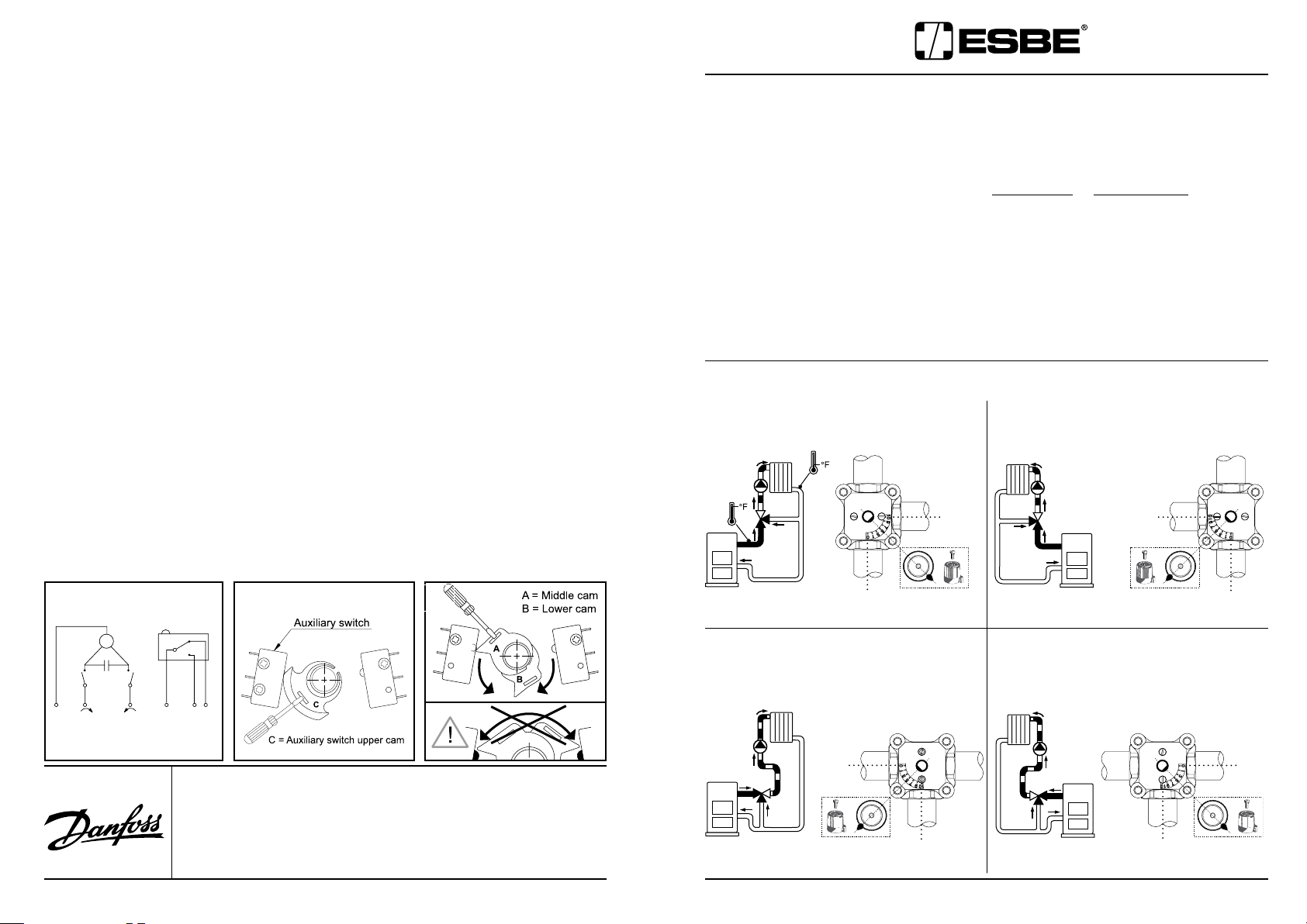
Wiring: 91M, 92M, 92-2M and 93M for “Floating” Signals (see ). For ESBE
M
L1
L1
N
1 2 3
92P and 92K2 actuators, refer to the actuator’s installation instructions.
Warning: Always turn off all electrical power before removing or servicing
the actuator.
–
The actuator is powered using a 24VAC transformer, 3VA minimum.
– Remove the four cover screws and lift the cover off the actuator.
– Remove one (or two) of the wiring knockouts and install one (or two) of the
“conduit fittings”. All wires must go through these fittings.
– Attach the “common” from the control (or transformer) to terminal “N”.
– Connect the control output for clockwise rotation to “Upper terminal L1”, and
connect the control output for counterclockwise rotation to “Lower terminal L1”
Auxiliary Switch
ESBE 91M, 92M, 92-2M and 93M actuators include one fully adjustable
–
auxiliary switch.
The wiring should be connected as shown in . To set the
switching position, turn the cam (see ).
Reinstall the cover and secure it, before turning on the power.
Adjusting the Degree of Rotation
–
ESBE 90 series actuators do not require adjustment when used with ESBE
valves. However if the actuator is used for an application that requires a different
degree of rotation, the middle and lower cams can be adjusted to provide
between 30° and 180° of rotation. For access to the cams, the cam operating the
aux switch must be removed. See . Always turn off all power before adjust-
ments are made.
Test: T
est the valve rotation to ensure the valve is allowed to fully open and
fully close. Rotations of 30° to 180° are possible via middle and lower cams for
applications that require them. For access, aux. switch cam must be removed.
ESBE 3-WAY VALVE
INSTALLATION INSTRUCTIONS
Pipe the Valve into the System
• ESBE 3-way valves can be piped for either 3-way Mixing or 3-way Diverting applications
• 3-way Mixing: 2 inputs, 1 output • 3-way Diverting: 1 input, 2 outputs
• The System port, or the port on the valve which will deliver the mixed water to the
system, must never be the center port.
• Install the valve so the actuator (if so equipped) will not be below the valve (ie.
facing the floor).
Orient the Valve Face Plate
• The face plate can be turned over and rotated to match your piping configuration.
3-WAY MIXING –
A) B)
Two temperature inputs, one blended output
10
10
For technical support or additional product information, contact:
Danfoss Inc.
7941 Corporate Drive
Baltimore, MD USA 21236
T
elephone: (433) 512 - 0266
Fax:
(443) 512 - 0270
E-mail:
heatinginfo@danfoss.com
www.na.heating.danfoss.com
4 1
Danfoss Inc.
6711 Mississauga Road · Suite 410
Mississauga, ON, L5N 2W3 Canada
T
elephone: (905) 285 - 2050
Fax:
(905) 285 - 2055
E-mail:
heatinginfo@danfoss.com
www.na.heating.danfoss.com
0
C) D)
0
10
0
0
10
Art.nr. 98140081 Ritn.nr 3285 Utg PC6
Page 2
INSTALLATION INSTRUCTIONS (Continued)
5
5
5
5
5
5
5
5
5
5
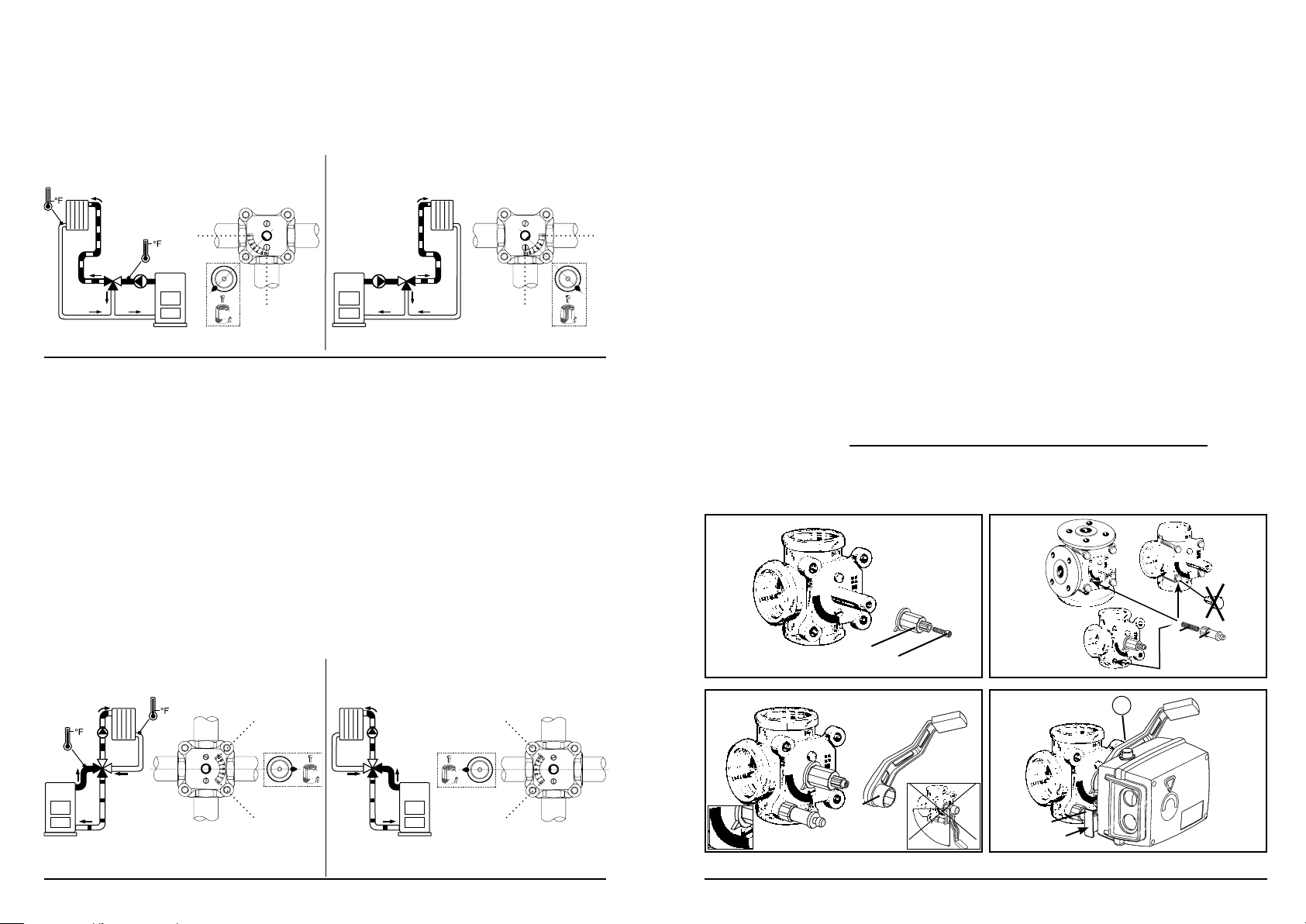
3-WAY DIVERTING –
for boiler return water control
Configurations shown below are suitable
E) F)
0
10
10
ESBE 4-WAY VALVE
INSTALLATION INSTRUCTIONS
Pipe the Valve into the System
• Pipe the valve in either one of the configurations shown below.
• Install the valve so the actuator (if so equipped) will not be below the valve (ie.
facing the floor).
Orient the Valve Face Plate
• The dial face plate is printed on both sides.
• If the 0 through 10 scale is facing correctly for your piping arrangement (A or B) as
shown below, proceed with mounting the actuator.
• Otherwise, remove the face plate with the 0 through 10 scale, and turn it over.
Then replace the face plate on the valve so it matches your piping configuration.
A) B)
ESBE Series 90 Actuator
INSTALLATION INSTRUCTIONS
(For Series 60 actuator mounting instructions, refer to installation instructions
included with actuator).
Place drive sleeve onto shaft and secure with screw . Rotate the sleeve
and valve shaft until the pointer is aligned to position 5 on scale plate.
0
Mount threaded stud in the lower left threaded hole. For 1½ and 2" valves
replace one of the cover bolts with the threaded stud. Tighten mounting piece
onto threaded stud.
Mount handle over drive sleeve. Handle must be mounted opposite to the
pointer of the drive sleeve, & facing away from .
Mount actuator onto sleeve so that mounting piece fits into the locking
piece . Push locking piece to lock in place. Labels are supplied to indicate
the direction of rotation. Determine the direction of rotation and mount the correct
label under the plastic front cover of actuator.
Note: Always
the handle does not interfere with the actuator mounting stud and mounting
piece.
Manual Operation: Always
Note position of drive sleeve pointer to be returned to. Depress the gray button,
“A”, on the side to release the handle. The valve can now be operated manually.
Never manually operate when gears are engaged.
test rotation of the valve in manual position mode to ensure that
disconnect power before operating by hand.
3F
3MG
3G
10
0
2 3
10
0
”CLICK”
A
 Loading...