

Page 1
INSTRUCTIONS
EKC 202A (115 V)
EKC 202B (115 V)
EKC 202C (115 V)
084R9976
t
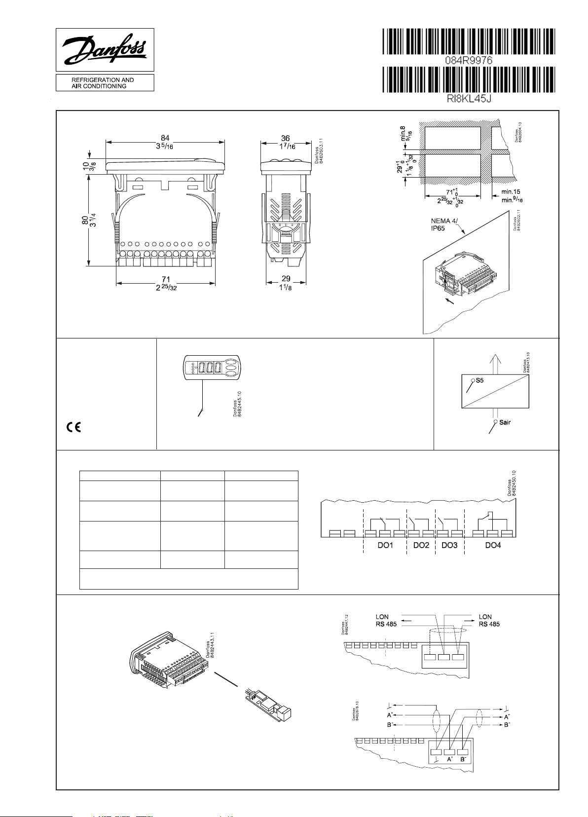
= 0 - +55°C
amb
115 V a.c.
50/60 Hz
2.0 VA
084R9976
Type: Pt 1000 (1000 Ω /0°C ) /
Ptc 1000 (1000 Ω /25°C ) /
NTC-M2020 (5000 Ω / 25°C)
( o06)
10 V < U < 256 V
DO1. Refrigeration * 10 (6) A
DO2. Defrost * 10 (6) A
DO3. Fan * 6 (3) A
DO4. Alarm, light or rail
heat *
* DO1 and DO2 are 16 A relays. DO3 and DO4 are 8 A relays. Max. load must be keept.
** Gold plating ensures make function with small contact loads
*** UL-approval based on 30000 couplings
CE (250 V a.c.) UL *** (240 V a.c.)
10 A Resistive
5FLA, 30LRA
10 A Resistive
5FLA, 30LRA
6 A Resistive
3FLA, 18LRA
4 (1) A
Min. 100 mA**
131 VA Pilot duty
4 A Resistive
131 VA Pilot duty
Data communication LON RS 485 / MOD-bus:
LON
MOD-bus
RI8KL45J 08-2010
Page 2
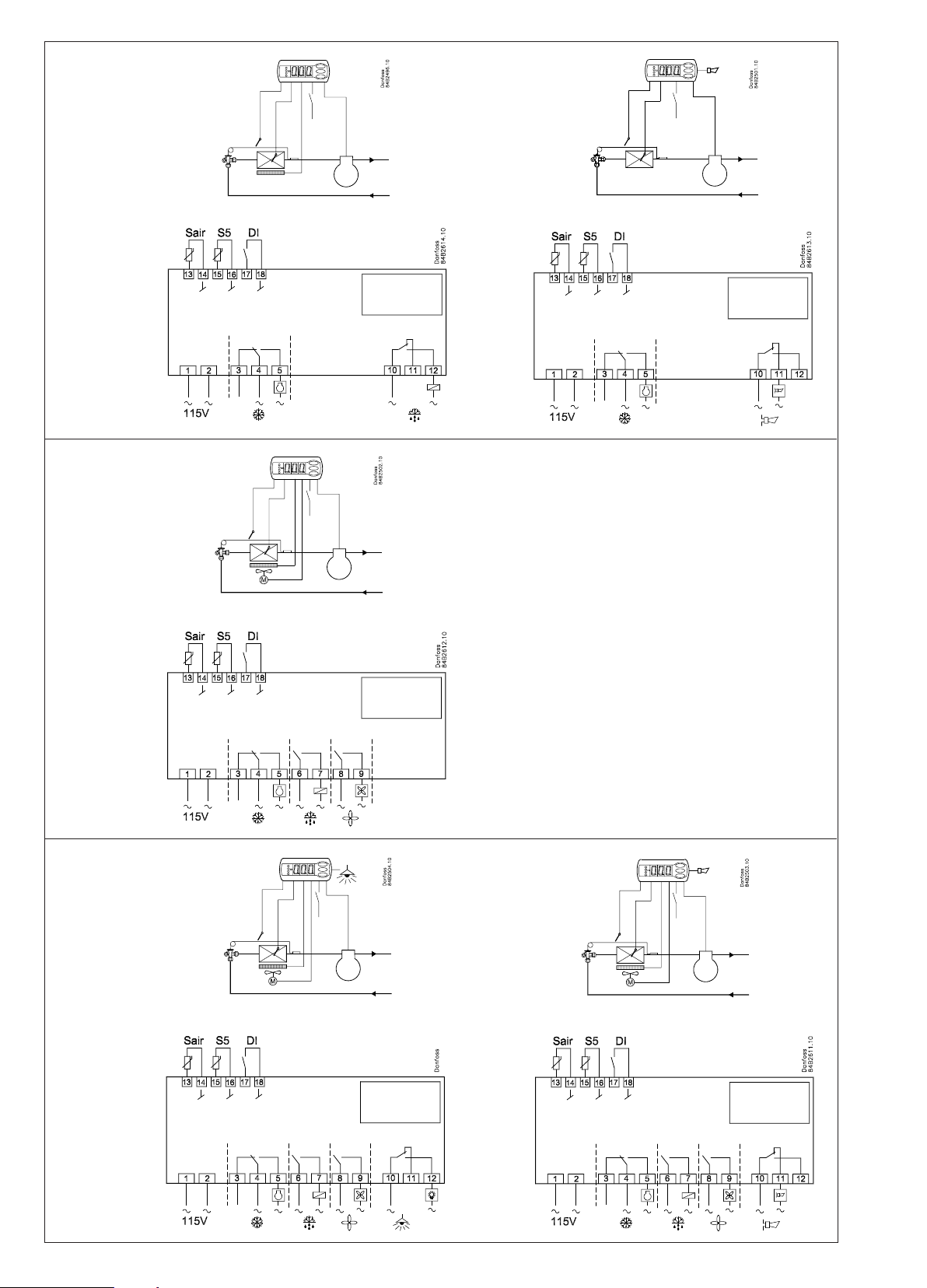
EKC 202A
*) AU:
Gold, Or, Oro
l = max. 15 m
EKC 202B
*) AU:
Gold , Or, Oro
l = max. 15 m
*)
*)
*)
EKC 202C
*) AU:
Gold, Or, Oro
l = max. 15 m
2 Instructions RI8KL45J © Danfoss 08/2010 EKC 202A, B, C
*)
*)
Page 3

The buttons
English
Set menu
1. Push the upper button until a parameter
is shown
2. Push the upper or the lower button and
find that parameter you want to change
3. Push the middle button until the
parameter value is shown
4. Push the upper or the lower button and
select the new value
5. Push the middle button again to enter
the value.
Set temperature
1. Push the middle button until the
temperature value is shown
2. Push the upper or the lower button and
select the new value
3. Push the middle button to select the
setting.
Reading the temperature at sensor S5
• Push briey the lower button
Manuel start or stop of a defrost
• Push the lower button for four
seconds.
Light emitting diode
= refrigeration
= defrost
= fan running
Flashes fast at alarm
Cutout alarm relay / see alarm code
• Push briey the upper button
Start-up:
Regulation starts when the voltage is on.
1 Go through the survey of factory settings. Make any necessary changes in the respective parameters.
2 For network. Set the address in o03 and then transmit it to the gateway/system unit with setting o04.
Parameters Controller
Function Codes
Normal operation
Temperature (set point) --- -50°C 50°C 2°C
Thermostat
Differential r01 0,1 K 20 K 2 K
Max. limitation of setpoint setting r02 -49°C 50°C 50°C
Min. limitation of setpoint setting r03 -50°C 49°C -50°C
Adjustment of temperature indication r04 -20 K 20 K 0.0 K
Temperature unit (°C/°F) r05 °C °F °C
Correction of the signal from Sair r09 -10 K 10 K 0 K
Manual service(-1), stop regulation(0), start regulation (1) r12 -1 1 1
Displacement of reference during night operation r13 -10 K 10 K 0 K
Activation of reference displacement r40 r39 OFF on OFF
Value of reference displacement (can be activated by r39 or DI) r40 -50 K 50 K 0 K
Alarm
Delay for temperature alarm A03 0 min 240 min 30 min
Delay for door alarm A04 0 min 240 min 60 min
Delay for temperature alarm after defrost A12 0 min 240 min 90 min
High alarm limit A13 -50°C 50°C 8°C
Low alarm limit A14 -50°C 50°C -30°C
Alarm delay DI1 A27 0 min 240 min 30 min
High alarm limit for condenser temperature (o70) A37 0°C 99°C 50°C
Compressor
Min. ON-time c01 0 min 30 min 0 min
Min. OFF-time c02 0 min 30 min 0 min
Compressor relay must cutin and out inversely (NC-function) c30 0 / OFF 1 / on 0 / OFF
Defrost
Defrost method (none/EL/gas) d01 no gas EL
Defrost stop temperature d02 0°C 25°C 6°C
Interval between defrost starts d03 0 hours 48 hours 8 hours
Max. defrost duration d04 0 min 180 min 45 min
Displacement of time on cutin of defrost at start-up d05 0 min 240 min 0 min
Drip off time d06 0 min 60 min 0 min
Delay for fan start after defrost d07 0 min 60 min 0 min
Fan start temperature d08 -15°C 0°C -5°C
Fan cutin during defrost
0: Stopped
1: Running
2: Running during pump down and defrost
Defrost sensor (0=time, 1=S5, 2=Sair) d10 0 2 0
Max. aggregate refrigeration time between two defrosts d18 0 hours 48 hours 0 hours
Defrost on demand - S5 temperature’s permitted variation during frost build-up. On
central plant choose 20 K (=off)
Fans
Fan stop at cutout compressor F01 no yes no
Delay of fan stop F02 0 min 30 min 0 min
Fan stop temperature (S5) F04 -50°C 50°C 50°C
Real time clock
Six start times for defrost.
Setting of hours.
0=OFF
Six start times for defrost.
Setting of minutes.
0=OFF
Clock - Setting of hours t07 0 hours 23 hours 0 hours
Clock - Setting of minute t08 0 min 59 min 0 min
t01-t06 0 hours 23 hours 0 hours
t11-t16 0 min 59 min 0 min
EKC
202A
d09 0 2 1
d19 0 K 20 K 20 K
EKC
202B
202C
EKC
Min.value
Max.value
Factory
setting
SW = 1.3x
Actual
setting
EKC 202A, B, C Instructions RI8KL45J © Danfoss 08/2010 3
Page 4

Clock - Setting of date t45 1 31 1
Clock - Setting of month t46 1 12 1
Clock - Setting of year t47 0 99 0
Miscellaneous
Delay of output signals after start-up o01 0 s 600 s 5 s
Input signal on DI1. Function:
0=not used. 1=status on DI1. 2=door function with alarm when open. 3=door alarm
when open. 4=defrost start (pulse-pressure). 5=ext.main switch. 6=night operation
7=change reference (activate r40). 8=alarm function when closed. 9=alarm function
when open. 10=case cleaning (pulse pressure). 11=Inject off when open.
Network address o03 0 119 0
On/Off switch (Service Pin message) o04 OFF ON OFF
Access code 1 (all settings) o05 0 100 0
Used sensor type (Pt /PTC/NTC) o06 Pt ntc Pt
Display step = 0.5 (normal 0.1 at Pt sensor) o15 no yes no
Max hold time after coordinated defrost o16 0 min 60 min 20
Configuration of light function (relay 4)
1=ON during day operation. 2=ON / OFF via data communication. 3=ON follows the DIfunction, when DI is selected to door function or to door alarm
Activation of light relay (only if o38=2) o39 OFF ON OFF
Case cleaning. 0=no case cleaning. 1=Fans only. 2=All output Off. o46 0 2 0
Access code 2 (partly access) o64 0 100 0
Save the controllers present settings to the programming key. Select your own number. o65 0 25 0
Load a set of settings from the programming key (previously saved via o65 function) o66 0 25 0
Replace the controllers factory settings with the present settings o67 OFF On OFF
Select application for S5 sensor (0=defrost sensor, 1= product sensor, 2=condenser sen-
sor with alarm)
Select application for relay 4: 1=defrost/light, 2= alarm o72 defrost /
Service
Temperature measured with S5 sensor u09
Status on DI1 input. on/1=closed u10
Status on night operation (on or off) 1=closed u13
Read the present regulation reference u28
Status on relay for cooling (Can be controlled manually, but only when r12=-1) u58
Status on relay for fans (Can be controlled manually, but only when r12=-1) u59
Status on relay for defrost. (Can be controlled manually, but only when r12=-1) u60
Temperature measured with Sair sensor u69
Status on relay 4 (alarm, defrost, light).(Can be controlled manually, but only when
r12=-1)
Factory setting
If you need to return to the factory-set values, it can be done in this way:
- Cut out the supply voltage to the controller
- Keep upper and lower button depressed at the same time as you recon nect the supply voltage
o02 0 11 0
o38 1 3 1
o70 0 2 0
u71
Alarm
Light /
Alarm
1 2 2
Fault code display Alarm code display Status code display
E1 Fault in controller A 1 High temperature alarm S0 Regulating
E6 Change battery + check clock A 2 Low temperature alarm S1 Waiting for end of the coordinated defrost
E 27 S5 sensor error A 4 Door alarm S2 ON-time Compressor
E 29 Sair sensor error A 5 Max. Hold time S3 OFF-time Compressor
A 15 DI 1 alarm S4 Drip-off time
A 45 Standby mode S10 Refrigeration stopped by main switch
A 59 Case cleasning S11 Refrigeration stopped by thermostat
A 61 Condenser alarm S14 Defrost sequence. Defrosting
S15 Defrost sequence. Fan delay
S16 Refrigeration stopped. (open DI input)
S17 Door open (open DI input)
S20 Emergency cooling
S25 Manual control of outputs
S29 Case cleaning
S32 Delay of output at start-up
non The defrost temperature cannot be dis-
played. There is stop based on time
-d- Defrost in progress / First cooling after
defrost
PS Password required. Set password
4 Instructions RI8KL45J © Danfoss 08/2010 EKC 202A, B, C
Page 5

Los botones
Español
Ajustar parámetros
1. Pulsar el botón superior hasta que
aparece el parámetro r01.
2. Pulsar los botones alto y bajo hasta
encontrar el parámetro desesado.
3. Pulsar el botón central para ver el valor
actual.
4. Pulsar los botones alto y bajo para
modificar el valor.
5. Pulsar el botón central para confirmar el
Ajustar la temperatura de corte
1. Pulsar el botón central para ver el valor
actual.
2. Pulsar los botones alto y bajo para
modificar el valor.
3. Pulsar el botón central para confirmar el
nuevo valor.
Leer la temperatura de la sonda S5
• Pulsar y soltar el botón bajo
Iniciar/parar un desescarche
manualmente
• Pulsar y mantener el botón bajo
durante 4s.
LED’s en el display
= refrigeración
= desescarche
= ventiladores
Parpadean cuando hay una alarma
nuevo valor.
Rearmar el relé de alarma / ver el código
de alarma
• Pulsar y soltar el botón alto
Puesta en marcha:
El equipo comienza a funcionar cuando se aplica alimentación eléctrica.
1 Revisar la programación por defecto (ver Menú de Parámetros) y ajustar los parámetros oportunos.
2 Si el equipo está conectado a un bus de comunicaciones, ajustar la dirección en o03 y enviar la dirección a la Gateway con o04.
Parámetros Controlador
Función Código
Funcionamiento normal
Temperatura de corte (set point) --- -50°C 50°C 2°C
Termostato
Diferencial del termostato r01 0,1 K 20 K 2 K
Límite máximo al ajustar la temperatura de corte r02 -49°C 50°C 50°C
Límite mínimo al ajustar la temperatura de corte r03 -50°C 49°C -50°C
Corrección de la temperatura en el display r04 -20 K 20 K 0.0 K
Unidades de temperatura (°C/°F) r05 °C °F °C
Calibración de la sonda Saire r09 -10 K 10 K 0 K
Marcha/paro interno: -1: modo manual, 0: EKC parado, 1: en marcha r12 -1 1 1
Desplazamiento de la temp. de corte durante la noche r13 -10 K 10 K 0 K
Activar el incremento de la temperatura de corte r39 OFF on OFF
Incremento de la temperatura de corte (grados) (activación por r39 o DI) r40 -50 K 50 K 0 K
Alarma
Retardo de alarma de temperatura (estándar) A03 0 min 240 min 30 min
Retardo de alarma de puerta A04 0 min 240 min 60 min
Retardo de alarma de temperatura (después de desescarche) A12 0 min 240 min 90 min
Límite de alarma por alta temperatura A13 -50°C 50°C 8°C
Límite de alarma por baja temperatura A14 -50°C 50°C -30°C
Retardo de la alarma asociada a DI A27 0 min 240 min 30 min
Límite de alarma por alta temperatura del condensador (con S5 y o70 = 2) A37 0°C 99°C 50°C
Compresor
Mínimo tiempo de compresor en marcha (minutos) c01 0 min 30 min 0 min
Mínimo tiempo de entre dos arranques consecutivos (minutos) c02 0 min 30 min 0 min
Invertir el funcionamiento de la salida DO1 (compresor) c30 0 / OFF 1 / on 0 / OFF
Desescarche
Tipo de desescarche (OFF/EL/gas) d01 no gas EL
Temperatura fin de desescarche d02 0°C 25°C 6°C
Intervalo de tiempo entre desescarches d03 0 horas 48 horas 8 horas
Duración máxima del desescarche d04 0 min 180 min 45 min
Desplazamiento del 1er desescarche tras dar tensión al equipo d05 0 min 240 min 0 min
Tiempo de goteo d06 0 min 60 min 0 min
Retardo del ventilador tras el desescarche d07 0 min 60 min 0 min
Temperatura arranque del ventilador d08 -15°C 0°C -5°C
Ventilador en marcha durante desescarche (no/yes)
0: parado
1: en marcha
2: en marcha durante el vaciado y el desescarche
Sonda de fin de desescarche (0=no (tiempo), 1=S5, 2=Saire) d10 0 2 0
Desescarche bajo demanda: tiempo acumulado refrigerando (0=Función cancelada) d18 0 horas 48 horas 0 horas
Desescarche bajo demanda: variación permitida a S5 (20 = Función cancelada) d19 0 K 20 K 20 K
Ventiladores
Parar ventilador al parar compresor (yes/no) F01 no yes no
Retardo de parada del ventilador F02 0 min 30 min 0 min
Temperatura de paro del ventilador (medida con S5) F04 -50°C 50°C 50°C
Reloj de tiempo real
Hasta seis horas (hh) de inicio de desescarche.
0=OFF
Los minutos (mm) de cada una de las 6 horas.
0=OFF
Ajuste del reloj - hora t07 0 horas 23 horas 0 horas
Ajuste del reloj - minutos t08 0 min 59 min 0 min
t01-t06 0 horas 23 horas 0 horas
t11-t16 0 min 59 min 0 min
EKC
202A
d09 0 2 1
EKC
202B
202C
EKC
Valor
- mín.
Valor
- máx.
Ajuste
fábrica
SW = 1.3x
Ajuste
actual
EKC 202A, B, C Instructions RI8KL45J © Danfoss 08/2010 5
Page 6

Ajuste del reloj - día t45 1 31 1
Ajuste del reloj - mes t46 1 12 1
Ajuste del reloj - año t47 0 99 0
Varios
Retardo de activación de salidas al dar tensión al equipo o01 0 s 600 s 5 s
Función de la entrada digital DI1:
o02 0 11 0
0=no utilizada. 1=comunica el estado de DI1. 2=puerta abierta y alarma. 3=sólo la
alarma de puerta. 4=pulso para iniciar un desescarche. 5=interruptor principal.
6=operación nocturna 7=desplazamiento temperatura de corte (activación r40).
8=alarma al cerrar el contacto 9=alarma al abrir el contacto. 10=limpieza del mueble
(pulso). 11= Inject off al abrir el contacto.
Dirección del EKC o03 0 240 0
Enviar la dirección del EKC a la gateway o04 OFF ON OFF
Código 1 de acceso a todos los parámetros (0= código desactivado) o05 0 100 0
Tipo de las sondas utilizadas (Pt /PTC/NTC) o06 Pt ntc Pt
Precisión del valor del display: yes = 0.5, no = 0,1 o15 no yes no
Máximo tiempo de espera tras un desescarche coordinado (sólo vía gateway) o16 0 min 60 min 20
Función de luz (relé 4; ver parámetro o72)
o38 1 3 1
1=ON durante operación dia. 2=ON / OFF vía bus de comunicaciones. 3=ON a la vez que
la DI cuando esa DI es para la función de puerta o alarma de puerta.
Activación del relé de luz vía bus de comunicaciones (sólo si o38=2) o39 OFF ON OFF
Limpieza del mueble. 0=no activo. 1=Sólo ventilador en ON. 2=Todas las salidas en OFF. o46 0 2 0
Código 2 de acceso a parte de los parámetros (0=desactivar código) o64 0 100 0
Guardar la programación de un EKC en una "copy-key". o65 0 25 0
Volcar la programación desde una "copy-key" a un EKC o66 0 25 0
Sustituir los "ajustes de fábrica" por la programación actual o67 OFF On OFF
Función de la sonda S5: 0 = desescarche, 1 = producto, 2 = alarma temp. condensador o70 0 2 0
Función del relé 4: 1=desescarche (EKC 202A) o luz (EKC 202C), 2= alarma o72 Desesc. /
Alarma
Luz /
Alarma
1 2 2
Parámetros informativos (servicio).
Temperatura medida con la sonda S5 u09
Estado de la entrada DI. (OFF = contacto abierto / ON = contacto cerrado) u10
Estado de la operación nocturna (OFF = no activa / ON = activa) u13
Temperatura de corte (set-point) u28
Estado del relé de frío (0/off = desactivado, 1/on = activado)* u58
Estado del relé del ventilador (0/off = desactivado, 1/on = activado)* u59
Estado del relé de desescarche (0/off = desactivado, 1/on = activado)* u60
Temperatura medida con la sonda Saire u69
Estado del relé 4 (0/off = desactivado, 1/on = activado)* u71
*) Pueden operarse manualmente si r12= -1
Ajustes de fábrica
Si se necesita volver a la programación de fábrica, se procederá así:
- Se corta la alimentación eléctrica al EKC
- Se restablece la alimentación eléctrica mientras se mantienen pulsados los botones
alto y bajo durante unos segundos.
Código de fallos Códigos de alarma Códigos de estado
E1 Fallo del controlador A 1 Alarma por alta temperatura de aire S0 Enfriando
E6 Fallo reloj (comprobar pila y "resetear" reloj) A 2 Alarma por baja temperatura de aire S1 Esperando final de desescarche coordinado.
E 27 Error en la sonda S5 A 4 Alarma de puerta S2 Compresor dentro del mín. tiempo en
marcha.
E 29 Error en la sonda Saire A 5 Expirada la espera tras desescarche
coordinado
S3 Compresor mín. tiempo entre arranques
consecutivos.
A 15 Alarma asociada a DI S4 Tiempo de goteo en curso.
A 45 EKC parado (ya sea por r12 ó por la DI) S10 Equipo parado (desde r12 ó desde DI)
A 59 Limpieza del mueble S11 Refrigeración parada. (Se ha alcanzado la
temperatura de corte).
A 61 Alarma de temperatura del condensador S14 Desescarchando
S15 Retraso del ventilador tras desescarche.
S16 Refrigeración parada. (entrada DI abierta)
S17 Puerta abierta
S20 Refrigeración en emergencia.
S25 Control manual, forzado, activo.
S29 Limpieza del mueble
S32 Retraso inicial al dar tensión al equipo.
non No se puede mostrar la temperatura de
desescarche. No hay sonda.
-d- Se está realizando un desescarche.
PS PS: introduzca contraseña (Código de
acceso)
The Product contains electrical components
6 Instructions RI8KL45J © Danfoss 08/2010 EKC 202A, B, C
And may not be disposed together with domestic waste.
Equipment must be separate collected with Electrical and Electronic waste. According to Local and currently valid legislation.
FC-SPMC
 Loading...