

Page 1
Technical brochure
EKA 183A Programming key
EKA 183A is the tool allowing fast installation
of the EKC, AK-CC and AK-CT refrigeration
controllers both in field and in production,
thanks to the easy setting of the parameters
with a simple plug and play action.
Features
y OEM and Service tool for quickly setting up a
controller
y Bidirectional communication from and to the
connected controller
y USB connection to PC
Page 2
General features
EKA 183A is used to copy setting to an EKC, AK-CC and AK-CT
controller.
It can be used to copy settings from one controller to another
controller of the same type. i.e. the same code number and software
version.
Can be used for:
EKC 102, EKC 202, EKC 204 and AK-CC 210.
EKC 3xx (but not EKC 301), EKC 4xx, EKC 5xx, AK-CC 450,
AK-CC 550 and AK-CT.
(ERC 10x and ERC11x only through docking station. Set the Data
Transfer “MODE=A” in this case as described in the last page.)
Function
Principle
EKA 183A is put into the controller. The controller is connected to the
mains.
Data can be copied from the programming key to the controller or
vice versa by operating the push button.
Pre-programming
EKA 183A is put into the PC’s USB port. The actual file is then set.
The settings are done using the “Microsoft Excel” program. (See next
page).
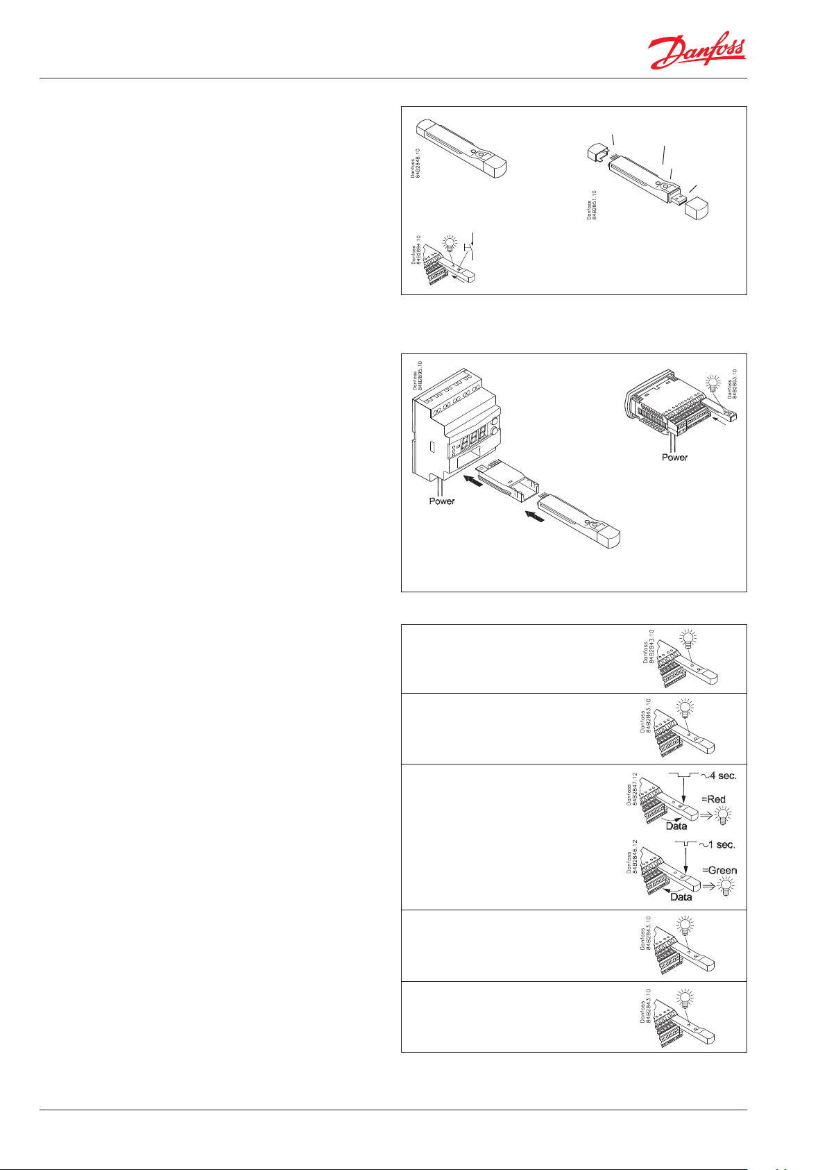
EKC-plug
LED
Push button
USB-plug
LED
1. The LED will flash yellow
when the programming key is put into the controller.
Here it is checked whether the data can be transferred.
2. Shortly afterwards
the LED constant light up yellow and the data transfer can start.
3. and 4. transfer of data:
• pushing the button briefly (1 sec.) will transfer data to the
controller (green LED flashes).
• a long push (at least 4 sec.) will transfer data from the controller to
the programming key (red LED flashes).
• (The transfer of data to the controller will start immediately
(i.e. without push the button), if this function has been activated.
See page 4.)
5. the LED light up constant
the transfer has finished.
If the LED flashes alternately red and green (and remains), an error
has occurred in the transfer. Put the programming key into the PC
and read the error code.
The two usual errors will be:
• the controller’s order number and software version do not match
the file that you are trying to copy to the controller.
• the programming key already contains a write-protected file of
the type you are trying to extract from the controller.
For EKC 3xx, EKC 4xx, EKC 5xx, AK-CC 450, AK-CC 550 and
AK-CT 200 the enclosed adapter must be used.
Yellow
1. Flashes
(checking)
Yellow
2. Light up constant
(await push)
3. Push
ashes
4. Flashes
(transfer data)
constant
5. Ligh up constant
(transfer finisched)
Danfoss A/S (ADAP-KOOL®/DF) | February 2017 DKRCC.PD.R1.07.022
Page 3

1
All parameters are transferred
All the set parameters are transferred. This also applies to the Main
Switch, refrigerant type, application number, address, etc.
There are no exceptions.
Ordering
Type Description Code no.
EKA 183A Programming key 084B8582
Principles and settings via PC
The programming key can only contain one file for each order
number, but there is room for many order numbers.
8020.ekc 8522.ekc 084B8942_.xls cong.cfg EKA183A.log
An example of the contents of a programming key.
The two first files (and similar types) will not be available before they have been
uploaded to the programming key.
By limiting it to one file, you control what is copied. Numerous files
with different settings, e.g. settings for cooling, frost, etc., will not be
mixed up.
When the file is transferred to a controller, the programming key will
check both the order number and the software version.
Both the order number and the software version on the controller
must match the file on the programming key, otherwise the transfer
will not work. The LED will flash to indicate an incomplete transfer.
In order to progress with an incomplete transfer, you must have a
file that corresponds to the one in the controller. But before this, you
must take into account the file that is already on the programming
key.
• If the file is write-protected, you cannot copy another one to the
programming key. The LED will indicate this by flashing.
• If it is not write-protected, it will be overwritten.
You can move the file to a PC, making it accessible later.
And then we go back to the incomplete transfer. If you have a file
with the correct software version, it must be copied over onto the
programming key and then to the controller.
• If you do not have the file, and want to save it for later, you can
copy the file from the controller to the programming key.
If you have several files for the same controller, we recommend that
you save them in different folders, so that they are kept apart from
each other. The programming key can only accept files if the name is:
XXXX.EKC, where XXXX is the last four digits in the order number, e.g.
084B8522.
Setting with “Microsoft Excel” program
The file is on the programming key.
084B8942_xxx.xls (xxx = software version)
Open the file and enable Macros.
The control screen is shown below.
At the bottom, you can save the file as a “Read-Only” file.
If you forget to do this, the file will be overwritten if you do a
“long push” on the programming key, thus transferring data from an
EKC to the programming key.
EKA 183A - Parameter editor
Ver. 1.02
Open Parameter file
File: C:\8520.ekc
Software version: 2.07
Model number: 8520 0
Text
--- Cutout °C 1 -50 50
r01 Differential 1 0.1 20
r02 Max cutout °C 1 -49 50
r03 Min cutout °C 1 -50 49
o17 Disp. S4 % 10 0 100
r04 Disp. Adj. K 1 -20 20
r05 Temp. unit 1 0
r09 Adjust S4 1 -10 10
Value MinMax
Edit parameter
Save file
Save file as “Read Only”
Danfoss A/S (ADAP-KOOL®/DF) | February 2017 DKRCC.PD.R1.07.02 3
Page 4

Data transfer
Two methods can be selected for transferring data:
• A: data transfer from the programming key to the controller occurs
at the same time as the programming key is pushed into the
controller.
• B: the unit is checked and the transfer takes place when the button
is pushed. (B= factory setting).
• P: reserved function.
Connect the programming key to a PC and find the file “Config.cfg”.
The file can be opened using the “WordPad” program.
Set the MODE line to either A or B.
## Sw. version. 1.xx
# Advanced users only
# EKA183A configuration file
#
# EKA183A configuration file
#
# MODE=A: EKA183A will automatically start uploading of parameters to EKC.
# MODE=B: EKA183A function is controlled by the push button.
# MODE=P: EKA183A is controlled by “EKA183A PC Toolkit”.
#
MODE=B
# End of configuration file
Error and status messages
If the LED flashes after a data transfer, the transfer is unsatisfactory.
Look at the error code in the log.
Description of errors and messages found in log:
001 Connection initialized to EKC, mode = button action
002 Connection initialized to EKC, mode = auto
003 Connection initialized to EKC, mode = PC/HID
004 Starting to copy from EKC to Programming Key
005 Done copying from EKC to Programming Key
006 Starting copy from Programming Key to EKC
007 DONE copy from Programming Key to EKC
008 A new configuration has been created
100 Unspecified E1 error
101 E2 error. Mode set to PC action, but no PC is connected
103 E2 error. Mode not set to BUTTON, AUTO or PC
103 E2 error. Tr ying to upload to a illegal PNU number.
Filename and line number specified in log
104 E2 error. Illegal value to upload, eg. out of range.
Filename and line number specified in log
105 E2 error. Tr ying to write “read only value”.
Filename and line number specified in log
106 E2 error. [PNU] section not found in parameter.
Filename specified in log
107 E2 error. Syntax error in PNU line.
Filename and line number specified in log
108 E2 error. No parameter file found to upload
109 E2 error. No configuration file found
110 E2 error. Syntax error in configuration file
111 E2 error. A parameter file for the current EKC is already
present and it is write protected
112 E2 error. A parameter file for the connected EKC exists, but
the software version in the file is different from the connected EKC
113 Not enough free space left on device
If the transferred data has to be used as “New factory setting”, add the
following text: FAC = Y
# MODE=P: EKA183A is controlled by “EKA183A PC Toolkit”.
#
MODE=B
FAC=Y
# End of configuration file
Modes vary based on product and connected device.
Please pay attention to choose the following modes, while the
Programming key is connected.
Mode Settings for Programming Key
Product Type
ERC 10X Series Mode A Not applicable
ERC 11X Series Mode A Not applicable
Plugged in Docking
Station
Connected to ERC prod-
uct directly
Read the log
Connect the programming key to a PC and find the file
“EKA183A. log”. The file can be opened using the “WordPad” program.
It displays the following information: No. of last event (here, line 23).
The last event will always be the last line. If there are more than
50 events, the first ones will be overwritten, so that the last 50 can
always be seen.
Latest line:23
001;00:00 01-01-00;8520;2.0.5;0;;
004;00:00 01-01-00;8520;2.0.5;0;;
005;00:00 01-01-00;8520;2.0.5;0;8520-000.ekc;
001;00:52 01-01-00;8020;1.1.6;0;;
001;01:03 01-01-00;8020;1.1.6;0;;
004;01:03 01-01-00;8020;1.1.6;0;;
005;01:03 01-01-00;8020;1.1.6;0;8020-000.ekc;
001;02:04 01-01-00;8020;1.1.6;0;;
006;02:04 01-01-00;8020;1.1.6;0;;
107;02:04 01-01-00;8020;1.1.6;0;8020-000.ekc;182
001;02:07 01-01-00;8020;1.1.6;0;;
006;02:07 01-01-00;8020;1.1.6;0;;
107;02:07 01-01-00;8020;1.1.6;0;8020-000.ekc;182
001;02:09 01-01-00;8020;1.1.6;0;;
004;02:09 01-01-00;8020;1.1.6;0;;
005;02:09 01-01-00;8020;1.1.6;0;8020-000.ekc;
001;03:22 01-01-00;8020;1.1.6;0;;
004;03:22 01-01-00;8020;1.1.6;0;;
005;03:22 01-01-00;8020;1.1.6;0;8020-000.ekc;
001;00:01 01-01-00;8520;2.0.5;0;;
004;00:01 01-01-00;8520;2.0.5;0;;
005;00:01 01-01-00;8520;2.0.5;0;8520-000.ekc;
• The first number is a code.
- Numbers below 100 are event codes.
- Numbers above 100 are error codes.
• The next number is the date and time of the event (It is the time
set in the controller that is used).
• Again, the next number is the last 4 digits of the controller’s order number.
• Then comes the software version — e.g. 2.05
• And the address set in o03.
• Then the recipient’s data. — Order number, address and “EKC”.
• If the event is an error, the last number in the line (e.g. 182) will be
information for Danfoss about where the error has occurred.
Danfoss can accept no responsibility for possible errors in catalogues, brochures and other printed material. Danfoss reserves the right to alter its products without notice. This also applies to products
already on order provided that such alternations can be made without subsequential changes being necessary in specifications already agreed.
All trademarks in this material are property of the respecitve companies. Danfoss and Danfoss logotype are trademarks of Danfoss A/S. All rights reserved.
Danfoss A/S (ADAP-KOOL®/DF) | February 2017 DKRCC.PD.R1.07.024
 Loading...