

Page 1
Service Manual
Steering
EHi Steering Valve
powersolutions.danfoss.com
Page 2

Service Manual
EHi Steering Valve
Revision history Table of revisions
Date Changed Rev
Sep 2017 First edition 0101
2 | © Danfoss | Sep 2017 AX00000350en-US0101
Page 3

Service Manual
EHi Steering Valve
Contents
Safety precautions
EHi Steering Valve versions
Exploded View and Parts List
EHi Full Exploded View...................................................................................................................................................................6
EHi Steering Valve Parts List......................................................................................................................................................... 6
Seal kits and spare parts for EHi.................................................................................................................................................. 9
Tools
EHi Steering Valve holding tool................................................................................................................................................10
Other required tools for EHi Steering Valve maintenance..............................................................................................11
Disassembly
Remove PVE from housing.........................................................................................................................................................12
Remove Coil from housing.........................................................................................................................................................13
Remove Priority Valve from housing...................................................................................................................................... 13
Remove Cut Off Valve from housing.......................................................................................................................................15
Remove Reaction Switch Valve (RSV) from housing......................................................................................................... 15
Remove PVFC/LS copy or LS shuttle valve from housing................................................................................................16
Remove Pilot reduction valve(s) from housing...................................................................................................................17
Remove Directional Valve from housing...............................................................................................................................18
Remove four remaining plugs near Pilot Relief Valve from housing.......................................................................... 18
Remove Pilot Relief Valve from housing................................................................................................................................19
Remove Shock valves from housing.......................................................................................................................................20
Remove steel plugs from ports.................................................................................................................................................21
Fully disassembled EHi.................................................................................................................................................................22
Assembly
Address seal kit............................................................................................................................................................................... 23
Insert steel plugs into ports........................................................................................................................................................23
Insert shock valves into housing.............................................................................................................................................. 24
Insert pilot relief valve into housing........................................................................................................................................25
Insert plugs near pilot relief valve into housing................................................................................................................. 26
Insert directional valve into housing...................................................................................................................................... 26
Insert plugs near directional valve into housing................................................................................................................27
Insert pilot reduction valve(s) into housing......................................................................................................................... 27
Insert PVFC/LS copy or LS shuttle valve into housing...................................................................................................... 28
Insert priority valve into housing............................................................................................................................................. 29
Insert cut off valve into housing...............................................................................................................................................30
Insert reaction switch valve (RSV) into housing..................................................................................................................30
Attach coil to housing.................................................................................................................................................................. 31
Attach PVE to housing..................................................................................................................................................................32
Testing of EHi
Setup for testing.............................................................................................................................................................................34
EHi for LS steering units...............................................................................................................................................................35
EHi for open center steering units...........................................................................................................................................36
Steering tests
Start up test......................................................................................................................................................................................38
Pilot relief valve...............................................................................................................................................................................38
Neutral positioning test...............................................................................................................................................................38
Cut off valve test.............................................................................................................................................................................38
RSV valve test...................................................................................................................................................................................38
Check for external leakage
Shock valves
Tightening torques for connections
©
Danfoss | Sep 2017 AX00000350en-US0101 | 3
Page 4

W
W
W
W
W
Service Manual
EHi Steering Valve
Safety precautions
Warning
Unintended vehicle or machine movement hazard.
Unintended movement of the machine or mechanism may cause injury to the technican or bystanders.
To prevent uintended movement, secure the machine or disable/disconnect the mechanism while
servicing.
Warning
Flammable cleaning solvents
Some cleaning solvents are flammable. To eliminate the risk of fire, do not use cleaning solvents in an
area where a source of ignition may be present.
Warning
Fluid under pressure
Escaping hydraulic fluid under pressure can have sufficient force to penetrate your skin causing serious
injury and/or infection. This fluid may also be hot enough to cause burns. Use caution when dealing with
hydraulic fluid under pressure. Relieve pressure in the system before removing hoses, fittings, gauges, or
components. Never use your hand or any other body part to check for leaks in a pressurized line. Seek
medical attention immediately if you are cut by hydraulic fluid.
Warning
Personal safety
Protect yourself from injury. Use proper safety equipment, including safety glasses at all times.
Warning
Product safety
Steering valves are safety components and therefore it is extremely important that the greatest care is
taken when servicing these products. There is not much wear on a steering valve and therefore they
normally outlast the application they are built into. Therefore the only recommended service work on
steering valve is:
Changing seals and O-rings
•
Disassemble, clean and assemble if contaminated
•
Make hydraulic testing including valve setting
•
4 | © Danfoss | Sep 2017 AX00000350en-US0101
Page 5

Service Manual
EHi Steering Valve
EHi Steering Valve versions
EHi versions
This service literature is valid for any version of EHi, the exploded view is universal.
These modules/valve functions are present only in some versions of EHi:
Reaction Switch Valve, RSV.
•
Pilot reduction valves, PRV; in versions with RSV: 2 PRV's. In any other versions: 1 PRV.
•
Priority Valve
•
PVFC valve/LS resolver or LS shuttle valve, or none.
•
Shock and suction valves.
•
©
Danfoss | Sep 2017 AX00000350en-US0101 | 5
Page 6
Service Manual
EHi Steering Valve
Exploded View and Parts List
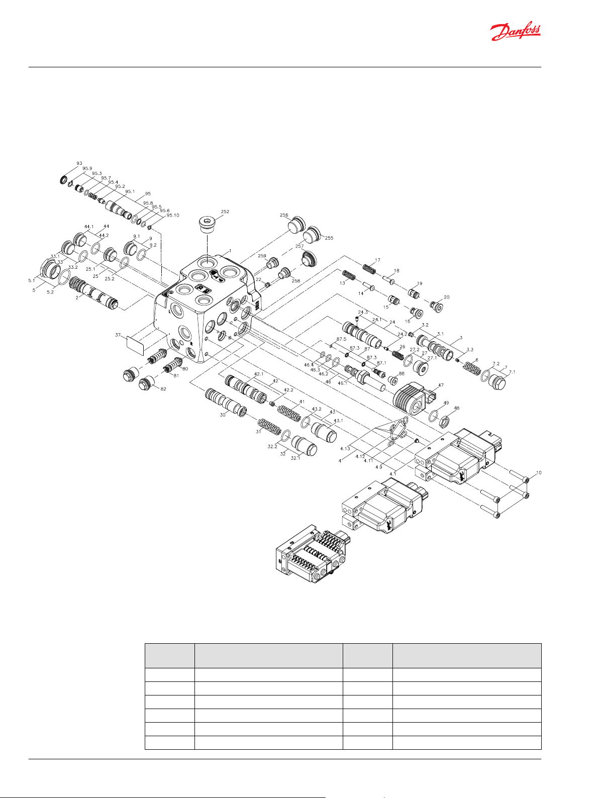
EHi Full Exploded View
EHi exploded view
EHi Steering Valve Parts List
EHi parts list
Item Description Number per
unit
1 Housing 1 2 Spool, EH steering 1 3 Priority valve spool 1 -
3.1 Spool 1 -
3.2 Orifice, PP 1 3.5 ± 0.5 N•m [31 ± 4.4 lbf•in]
3.3 Orifice, dynamic 1 1 ± 0.1 N•m [8.9 ± 0.9 lbf•in]
Tightening torque
6 | © Danfoss | Sep 2017 AX00000350en-US0101
Page 7
Service Manual
EHi Steering Valve
Exploded View and Parts List
EHi parts list (continued)
Item Description Number per
unit
4 PVE 1 -
4.1 PVE actuator 1 -
4.9 Filter 1 -
4.11 O-ring Ø8x2 1 -
4.12 O-ring Ø30x2.5 1 -
4.13 O-ring Ø10x2 3 5 Plug with O-ring 1 45 ± 5 N•m [398.3 ± 44.3 lbf•in]
5.1 Plug 1 -
5.2 O-ring Ø23.3x2.40 1 6 Compression spring 1 7 Plug with O-ring 1 45 ± 5 N•m [398.3 ± 44.3 lbf•in]
7.1 Plug 1 -
7.2 O-ring Ø17.40x2.10 1 9 Plug with O-ring 1 45 ± 5 N•m [398.3 ± 44.3 lbf•in]
9.1 Plug 1 -
9.2 O-ring Ø17.4x2.1 1 10 Screw 4 8 ± 1 N•m [70.8 ± 8.9 lbf•in]
13 Compression spring 2 14 Cone, pilot supply 1 15 Spool, pilot supply 1 16 Plug with O-ring 1 30 ± 3 N•m [265.5 ± 26.6 lbf•in]
17 Compression Spring 1 18 Cone, pilot supply 1 19 Spool, pilot supply 1 20 Plug with O-ring 1 30 ± 3 N•m [265.5 ± 26.6 lbf•in]
22 Orifice, LS 1 3.5 ± 0.5 N•m [31 ± 4.4 lbf•in]
24 Spool PVFC/LS resolver 1 -
24.1 Spool 1 -
24.2 Check valve 1 1.4 ± 0.2 N•m [12.4 ± 1.8 lbf•in]
24.3 Check valve 1 1.4 ± 0.2 N•m [12.4 ± 1.8 lbf•in]
25 Plug with O-ring 1 45 ± 5 N•m [398.3 ± 44.3 lbf•in]
25.1 Plug 1 26 Compression spring 1 27 Plug with O-ring 1 45 ± 5 N•m [398.3 ± 44.3 lbf•in]
27.1 Plug 1 -
27.2 O-ring Ø17.4x2.10 1 30 Spool, RSV 1 31 Compression spring 1 32 Plug with O-ring 1 45 ± 5 N•m [398.3 ± 44.3 lbf•in]
32.1 Plug 1 -
32.2 O-ring Ø17.40x2.10 1 33 Plug with O-ring 1 45 ± 5 N•m [398.3 ± 44.3 lbf•in]
33.1 Plug 1 -
33.2 O-ring Ø17.4x2.1 1 -
Tightening torque
©
Danfoss | Sep 2017 AX00000350en-US0101 | 7
Page 8
Service Manual
EHi Steering Valve
Exploded View and Parts List
EHi parts list (continued)
Item Description Number per
unit
37 Label with cover 1 41 Compression spring 1 42 Spool, Cut off 1 -
42.1 Spool 1 -
42.2 Plug 1 3.5 ± 0.5 N•m [31 ± 4.4 lbf•in]
43 Plug with O-ring 1 45 ± 5 N•m [398.3 ± 44.3 lbf•in]
43.1 Plug 1 -
43.2 O-ring Ø17.40x2.10 1 44 Plug with O-ring 1 45 ± 5 N•m [398.3 ± 44.3 lbf•in]
44.1 Plug 1 -
44.2 O-ring Ø17.4x2.1 1 46 Spool kit 1 -
46.1 Spool, pilot dump 1 15 ± 2 N•m [132.8 ± 17.7 lbf•in]
46.2 O-ring Ø9.25x1.78 1 -
46.3 O-ring Ø7.65x1.78 1 -
46.4 O-ring Ø13.5x2.08 1 47 Coil 1 48 Nut 1 5 ± 1 N•m [44.3 ± 8.9 lbf•in]
49 O-ring Ø10x2 1 80 Shock valve 2 81 Spring 2 82 Plug with O-ring 2 35 ± 3 N•m [309.8 ± 26.6 lbf•in]
87 LS shuttle valve 1 10 ± 1 N•m [88.5 ± 8.9 lbf•in]
87.1 Cartridge housing with ball 1 -
87.3 O-ring Ø5x1.5 2 -
87.5 O-ring Ø4.0x1.0 1 88 Plug 1 12.6 ± 0.6 N•m [111.5 ± 5.3 lbf•in]
93 Plug 1 95 PV valve 1 20 ± 3 N•m [177 ± 26.6 lbf•in]
95.1 Cartridge 1 -
95.2 Cone 1 -
95.3 Adjusting screw 1 -
95.4 Compression spring 1 -
95.5 Backup ring 1 -
95.6 O-ring Ø8x1.5 1 -
95.7 O-ring Ø7.5x1.5 1 -
95.8 O-ring Ø11x2 1 -
95.9 Lock ring 1 -
95.10 Filter 1 252 Plug 1 45 ± 5 N•m [398.3 ± 44.3 lbf•in]
255 Plug 1 45 ± 5 N•m [398.3 ± 44.3 lbf•in]
256 Plug 1 45 ± 5 N•m [398.3 ± 44.3 lbf•in]
257 Plug with O-ring 1 45 ± 5 N•m [398.3 ± 44.3 lbf•in]
Tightening torque
8 | © Danfoss | Sep 2017 AX00000350en-US0101
Page 9
Service Manual
EHi Steering Valve
Exploded View and Parts List
EHi parts list (continued)
Seal kits and spare parts for EHi
Seal kits and spare parts for EHi
Item Description Number per
258 Plug 1 20 ± 3 N•m [177 ± 26.6 lbf•in]
259 Plug 1 20 ± 3 N•m [177 ± 26.6 lbf•in]
Part Code number Item
Seal kit for EHi 11191725 5.2, 7.2, 9.2, 16, 20, 25.2, 27.2, 32.2, 33.2, 43.2,
Coil, DEUTSCH: D08 12V DE 322113 11084688 47
Coil, DEUTSCH: D08 24V DE 322115 11192696 47
Spare part bag containing: 1 plug. O-ring for
shock valve For replacement shock valves
please refer to PVG 32 Technical information,
document number 520L0344
Spare part bag containing: Cartridge spool
for pilot dump, Nut and O-ring
Seal kit for Cartridge spool for pilot dump 120433 46.2, 46.3, 46.4
Seal kit for Pilot relief valve 155L6870 95.5, 95.6, 95.7, 95.8, 95.9, 95.10
Seal kit for PVE 157B4997 4.9, 4.11, 4.12, 4.13
157B2002 82
11085713 46, 48, 49
unit
Tightening torque
44.2, 49, 2x 87.3, 87.5, 88, 93
©
Danfoss | Sep 2017 AX00000350en-US0101 | 9
Page 10
Min. 12
4±0.2
Ø16
Ø12±0.2
45°
B
B
125.5
33.5
68
16.5
93
151
C
C
B-B
Service Manual
EHi Steering Valve
Tools
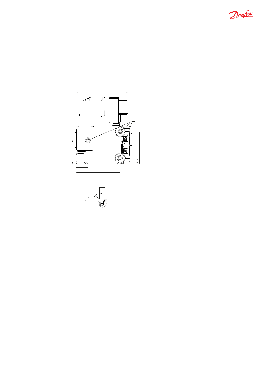
EHi Steering Valve holding tool
It is recommended to use appropriate steel plate with mounting holes 3x Ø 10 mm matching mounting
thread holes, C, on mounting side of EHi.
Mounting dimensions for EHi holding tool
C parameters
M8 x 1.25
12 mm deep
10 | © Danfoss | Sep 2017 AX00000350en-US0101
Page 11
Service Manual
EHi Steering Valve
Tools
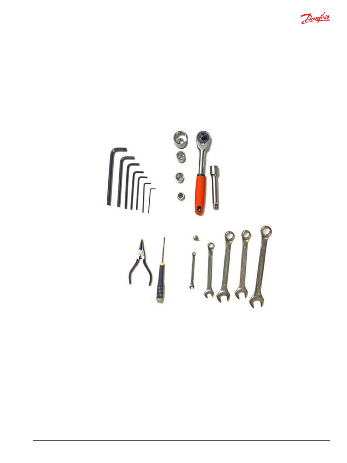
Other required tools for EHi Steering Valve maintenance
A list of tools required for disassembly and reassembly of EHi Steering Valve for inspection and
maintenance.
Tool for removing/assembling pilot relief valve cartridge:
Code Number: 155L6494
These tools are not available from Danfoss:
•
Torque wrench 0 - 70 Nm
•
13, 18, 19, and 32 mm socket spanner
•
2, 3, 4, 5, 6, 8, and 10 mm Hex keys
•
2mm screwdriver
•
13, 18, 19 mm, and 7/8 inch ring spanner.
•
Inside circlip pliers
•
Magnet, max outer diameter: 9 mm
•
Tweezers (not pictured)
©
Danfoss | Sep 2017 AX00000350en-US0101 | 11
Page 12
4.13
4.12
4.11
10
4.9
4.1
Service Manual
EHi Steering Valve
Disassembly
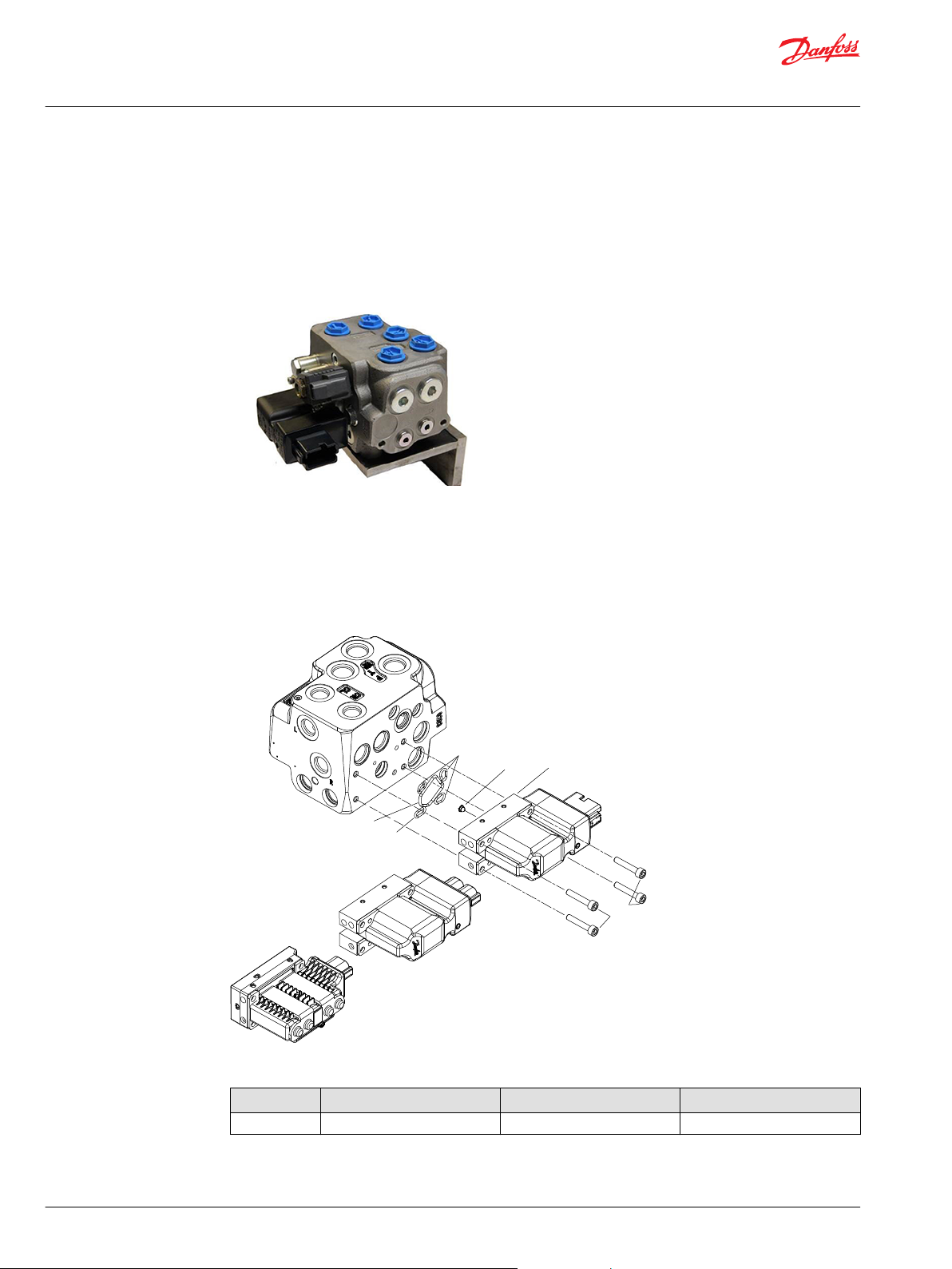
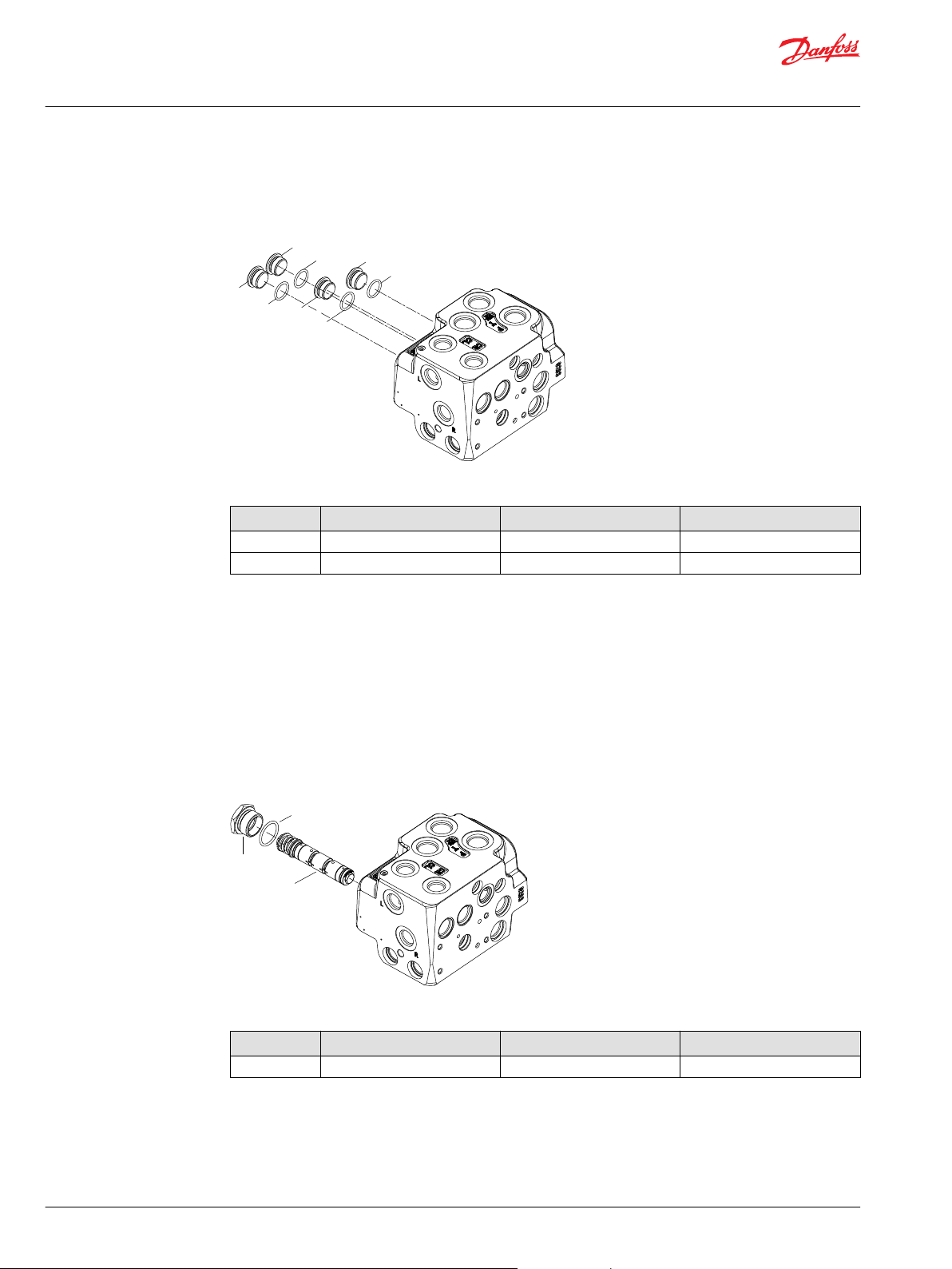
Remove PVE from housing
This section will show you how to fully disassemble the EHi Steering Valve for inspection, cleaning, and
maintenance.
To disassemble EHi Steering Valve follow these steps.
Place the unit on the holding tool.
Use 3 pcs M8 x 1.25, length: 10 mm, plus thickness of console plate.
EHi Steeering Valve mounted on holding tool.
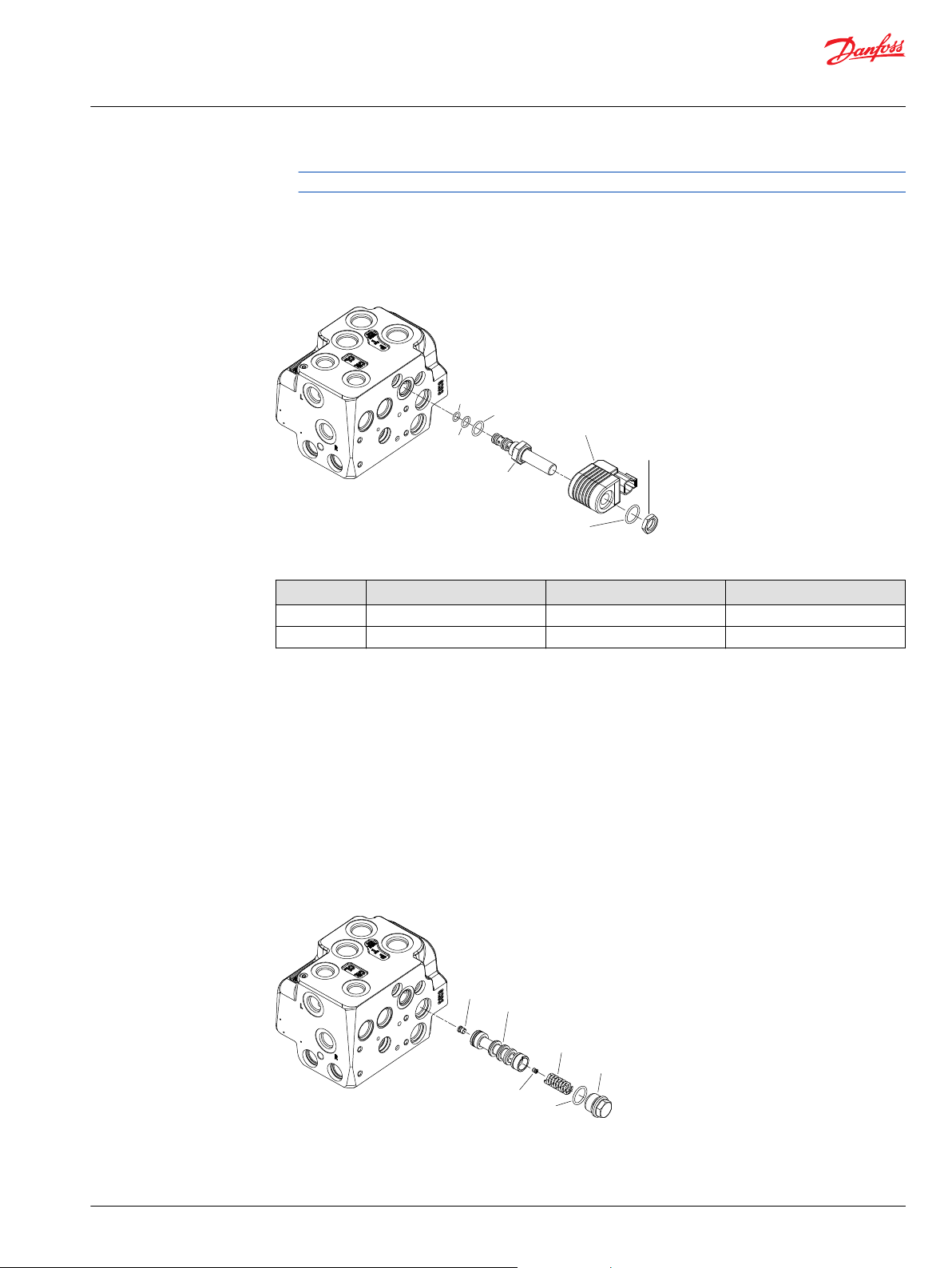
To remove the PVE from the EHi Steering Valve housing, follow these steps.
The PVE is attached to the housing with four screws. Five O-rings seal the unit in place, and a filter is also
found between the unit and the housing itself.
PVE parts and housing
Wrench size and torque
Item Description Wrench Size Torque
10 (x4) Screw 5 mm internal hex 8 ± 1 N•m [70.8 ± 8.9 lbf•in]
1. Screw out the four screws (10) for PVE (4) using a 5 mm Hex key .
2. Remove the PVE (4).
O-rings (4.11, 4.12, and 4.13), and filter (4.9) are fitted to the mounting surface of the PVE.
12 | © Danfoss | Sep 2017 AX00000350en-US0101
Page 13
46.4
46.3
46.2
46.1
47
48
49
3.2
3.1
3.3
6
7.2
7.1
Service Manual
EHi Steering Valve
Disassembly
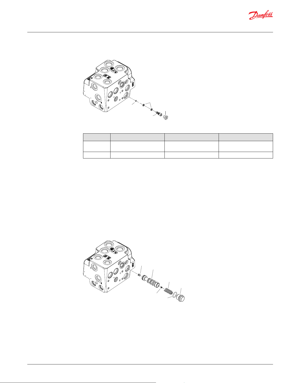
Remove Coil from housing
One or more O-rings may stick to the EHi housing. Remove before proceeding.
To remove the Coil from the EHi Steering Valve housing, follow these steps.
Coil parts and housing
Wrench size and torque
Item Description Wrench size Torque
48 Nut 19 mm external hex 5 ± 1 N•m [44.3 ± 8.9 lbf•in]
46.1 Spool, pilot dump 7/8 inch external hex 15 ± 2 N•m [132.8 ± 17.7 lbf•in]
1. Screw off the nut (48) using a 19 mm socket or ring spanner.
2. Remove the O-ring (49) using a 2 mm flat head screwdriver.
3. Lift off the Coil (47).
4. Screw out the cartridge spool (46) using a 7/8 inch ring spanner.
O-rings (46.2, 46.3, and 46.4) are fitted on cartridge spool (46).
Remove Priority Valve from housing
To remove Priority Valve from the EHi Steering Valve housing, follow these steps.
The valve is removed in a three-step sequence, involving the plug, spring, and the spool.
Remove the Priority Valve
Priority Valve parts and housing
©
Danfoss | Sep 2017 AX00000350en-US0101 | 13
Page 14
Service Manual
EHi Steering Valve
Disassembly
Wrench size and torque
Item Description Wrench size Torque
7 Plug with O-ring 18 mm external hex 45 ± 5 N•m [398.3 ± 44.3 lbf•in]
3.2 Orifice, PP 3 mm internal hex 3.5 ± 0.5 N•m [31 ± 4.4 lbf•in]
3.3 Orifice, dynamic 2 mm internal hex 1 ± 0.1 N•m [8.9 ± 0.9 lbf•in]
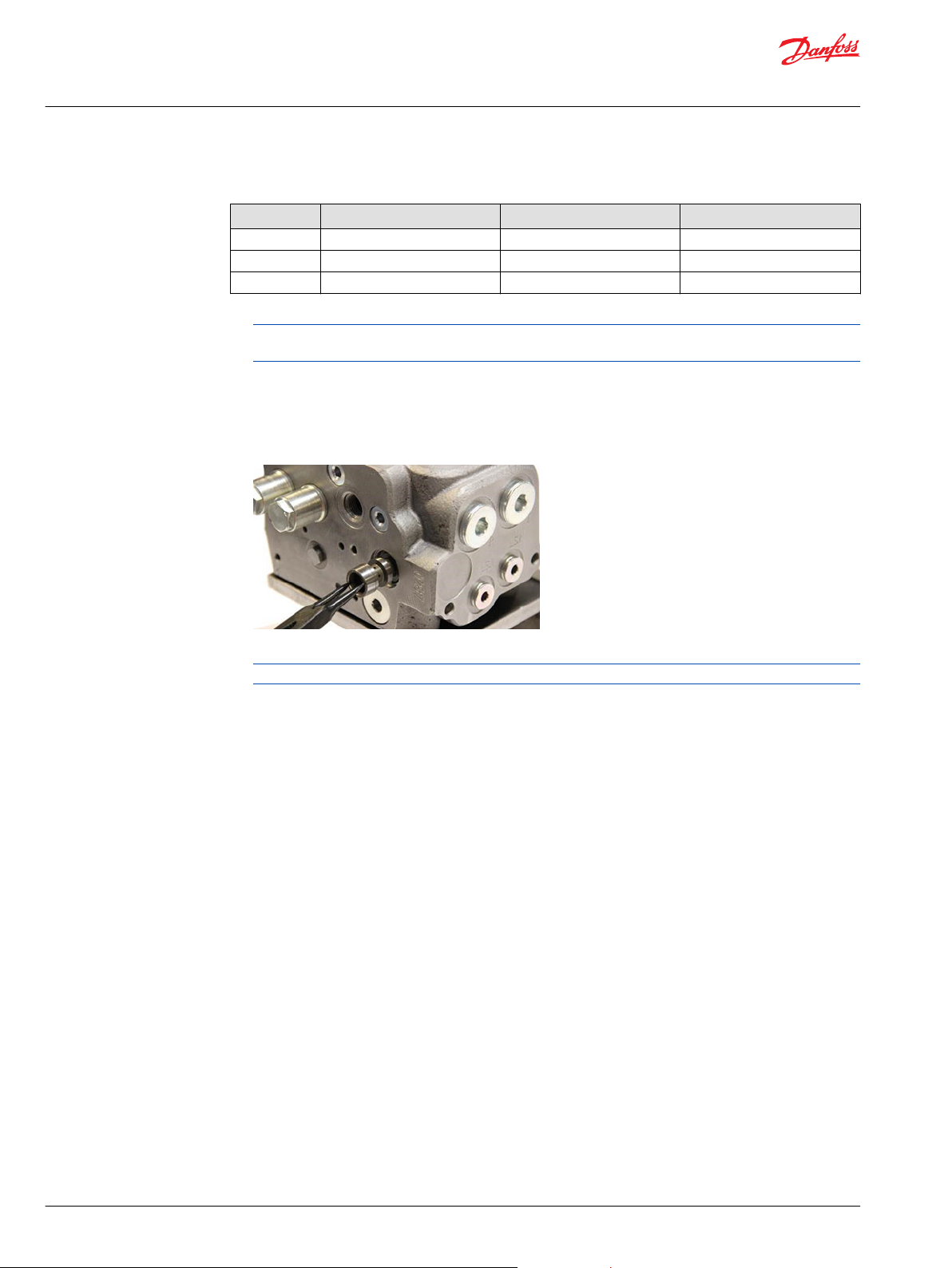
1. Screw out the plug (7) using an 18 mm socket or ring spanner.
On EHi versions without priority valve, only plug (7) with hex key profile is present. Screw out this
plug using an 8 mm Hex key.
O-ring (7.2) is fitted to the plug.
2. Remove the spring (6).
3. Remove the priority valve spool (3).
Remove priority valve spool with circlip pliers.
Orifices (3.2 and 3.3) are screwed into spool (3.1)
Orifice (3.3) is not present in the "Static" type priority valve spool.
a) Before removing orifices (3.2 and 3.3): fix the spool in a vice with aluminum jaws.
b) Screw out PP orifice (3.2) using a 3 mm Hex key.
c) Screw out dynamic orifice (3.3) using a 2 mm Hex key.
14 | © Danfoss | Sep 2017 AX00000350en-US0101
Page 15

42.1
42.2
41
43.2
43.1
30
31
32.2
32.1
Service Manual
EHi Steering Valve
Disassembly
Remove Cut Off Valve from housing
Remove the cut off valve.
Cut Off Spool parts and housing
Wrench size and torque
Item Description Wrench size Torque
43 Plug with O-ring 18 mm external hex 45 ± 5 N•m [398.3 ± 44.3 lbf•in]
42.2 Plug 3 mm internal hex 3.5 ± 0.5 N•m [31 ± 4.4 lbf•in]
1. Screw out the plug (43) for the cut off spool using an 18 mm socket or ring spanner.
O-ring (43.2) is fitted to the plug.
2. Remove the spring (41) for the cut off spool.
3. Remove the cut off spool (42).
Plug (42.2) is present in some cut off spools (42.1).
Remove Reaction Switch Valve (RSV) from housing
To remove the Reaction Switch Valve (RSV) from the EHi housing, follow these steps.
If RSV (Reaction Switch Valve) is present:
RSV parts and housing
©
Danfoss | Sep 2017 AX00000350en-US0101 | 15
Page 16

24.3
24.2
27.2
26
27.1
24.1
Service Manual
EHi Steering Valve
Disassembly
Wrench size and torque
Item Description Wrench size Torque
32 Plug with O-ring 18 mm external hex 45 ± 5 N•m [398.3 ± 44.3 lbf•in]
1. Screw out the plug (32) using an 18 mm socket or ring spanner.
O-ring (32.2) is fitted to the plug.
2. Remove the spring (31).
3. Remove the RSV spool (30).
Remove PVFC/LS copy or LS shuttle valve from housing
To remove PVFC/LS copy or LS shuttle valve from EHi Steering Valve housing, follow these steps.
•
If PVFC/LS copy valve is present, perform steps 1-3, below.
•
Alternative is LS shuttle valve (parts 88 and 87), in that case, follow steps 4 and 5, below.
•
If there is no valve at all, only plug (88) will be present. Screw out this plug as described in step 4,
below.
Remove the PVFC valve:
PVFC valve parts and housing
Wrench size and torque
Item Description Wrench size Torque
27 Plug with O-ring 8 mm internal hex 45 ± 5 N•m [398.3 ± 44.3 lbf•in]
24.2 Check Valve - 1.4 ± 0.2 N•m [12.4 ± 1.8 lbf•in]
24.3 Check Valve - 1.4 ± 0.2 N•m [12.4 ± 1.8 lbf•in]
1. Screw out the plug (27) using an 8mm Hex key.
O-ring (27.2) is fitted to the plug.
2. Remove the spring (26).
3. Remove the PVFC spool (24).
Some PVFC spools have check valves (24.2 and 24.3), which are screwed into spool (24.1).
If the PVFC/LS copy valve is absent, and the LS shuttle valve (88 and 87) is present instead, perform the
following steps:
16 | © Danfoss | Sep 2017 AX00000350en-US0101
Page 17

87.5
87.1
88
87.3
13
14
15
16
17
18
19
20
Service Manual
EHi Steering Valve
Disassembly
LS Shuttle valve/plug and housing
Wrench size and torque
Item Description Wrench size Torque
88 Plug 5 mm internal hex 12.6 ± 0.6 N•m [111.5 ± 5.3
lbf•in]
87 LS Shuttle valve 5 mm internal hex 10 ± 1 N•m [88.5 ± 8.9 lbf•in]
4. Screw out the plug (88) using a 5 mm Hex key.
O-ring (27.2) is fitted to the plug.
5. Screw out the shuttle valve (87) using a 5 mm Hex key.
O-rings (2x 87.3 and 87.5) are fitted to the valve.
Remove Pilot reduction valve(s) from housing
To remove Pilot reduction valve(s) from EHi Steering Valve housing, follow these steps.
These steps will explain how to remove the pilot valve or valves from the EHi Steering Valve housing. If
there is a second valve (17, 18, 19, and 20 are present), repeat these three steps for each valve.
Remove the Pilot reduction Valve(s)
Pilot reduction valve(s) parts and housing
Wrench size and torque
Item Description Wrench size Torque
16 Plug with O-ring 6 mm internal hex 30 ± 3 N•m [265.5 ± 26.6 lbf•in]
20 Plug with O-ring 6 mm internal hex 30 ± 3 N•m [265.5 ± 26.6 lbf•in]
1. Screw out the plug (16, and if present, 20) using a 6 mm Hex key .
O-ring (16.2) is fitted on plug.
2. Remove the spool (15, and if present, 19).
3. Remove the cone (14, and if present, 18) and spring (13, and if present, 17), eventually with magnet.
©
Danfoss | Sep 2017 AX00000350en-US0101 | 17
Page 18

5.1
5.2
2
33.1
33.2
25.1
25.2
44.1
44.2
9.1
9.2
Service Manual
EHi Steering Valve
Disassembly
Remove Directional Valve from housing
To remove the Directional Valve from the housing, follow these steps.
Remove the directional spool.
Directional spool parts and housing
Wrench size and torque
Item Description Wrench size Torque
5 Plug with O-ring 32 mm external hex 45 ± 5 N•m [398.3 ± 44.3 lbf•in]
1. Screw out the plug (5) using a 32 mm socket spanner.
O-ring (5.2) is fitted to the plug.
2. Remove the directional spool (2).
Remove four remaining plugs near Pilot Relief Valve from housing
To remove the four remaining plugs in this area, follow these steps.
Remove the four remaining plugs from this side of the housing.
Four plugs remain on this side
Wrench size and torque
Item Description Wrench size Torque
9 Plug with O-ring 8 mm internal hex 45 ± 5 N•m [398.3 ± 44.3 lbf•in]
25 Plug with O-ring 8 mm internal hex 45 ± 5 N•m [398.3 ± 44.3 lbf•in]
18 | © Danfoss | Sep 2017 AX00000350en-US0101
Page 19

93
95.9
95.3
95.7
95.4
95.2
95.1
95.8
95.5
95.6
95.10
Service Manual
EHi Steering Valve
Disassembly
Wrench size and torque (continued)
Item Description Wrench size Torque
33 Plug with O-ring 8 mm internal hex 45 ± 5 N•m [398.3 ± 44.3 lbf•in]
44 Plug with O-ring 8 mm internal hex 45 ± 5 N•m [398.3 ± 44.3 lbf•in]
1. Screw out the plug (9) using an 8 mm Hex key.
O-ring (9.2) is fitted to the plug
2. Screw out the plug (25) using an 8 mm Hex key.
O-ring (25.2) is fitted to the plug.
3. Screw out the plug (33) using an 8 mm Hex key.
O-ring (33.2) is fitted to the plug.
4. Screw out the plug (44) using an 8 mm Hex key.
O-ring (44.2) is fitted to the plug.
Remove Pilot Relief Valve from housing
To remove the Pilot Relief Valve from the EHi Steering Valve housing, follow these steps.
Remove the Pilot Relief Valve
Pilot Relief Valve parts and housing.
Wrench sizes and torque
Item Description Wrench size Torque
93 Plug 2 mm Screwdriver 95 PV valve cartridge Danfoss key (see below) 20 ± 3 N•m [177 ± 26.6 lbf•in]
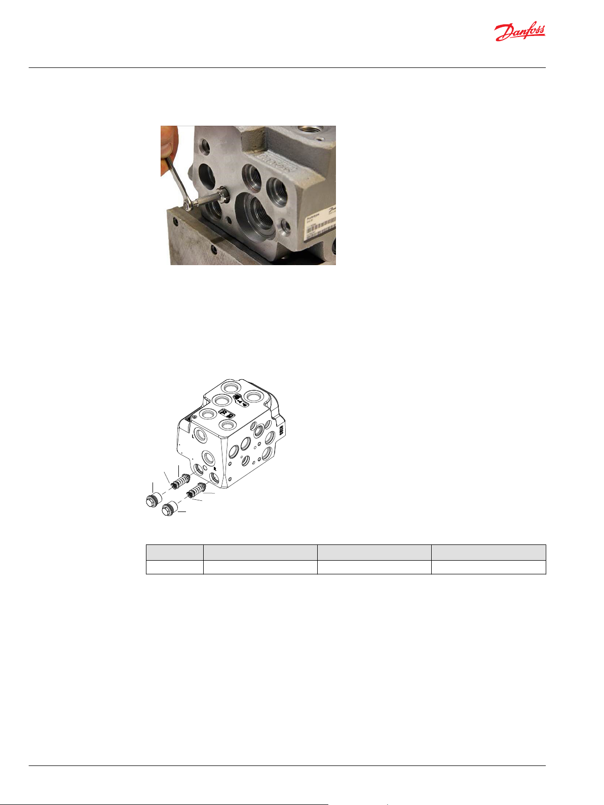
1. Remove the plug (93) for the pilot relief valve (95) using a screwdriver.
2. Screw out the PV valve cartridge (95) using special key.
Danfoss code 155L6494.
©
Danfoss | Sep 2017 AX00000350en-US0101 | 19
Page 20
82
81
80
82
81
80
Service Manual
EHi Steering Valve
Disassembly
Remove valve cartridge with Danfoss key.
Remove Shock valves from housing
To remove shock valves from EHi Steering Valve housing, follow these steps.
If the EHi does have shock valves, remove them by following steps one and two below for each shock
valve.
Remove Shock Valve(s) from housing.
Shock Valves and housing
Wrench size and torque
Item Description Wrench size Torque
82 (x2) Plug with O-ring 13 mm external hex 35 ± 3 N•m [309.8 ± 26.6 lbf•in]
1. Screw out the plugs (82) using a 13 mm socket or ring spanner .
2. Remove the shock valves (80) with conical springs (81).
20 | © Danfoss | Sep 2017 AX00000350en-US0101
Page 21

252
256
255
257
258
259
22
Service Manual
EHi Steering Valve
Disassembly
Remove steel plugs from ports
If the EHi has steel plugs in ports, perform the following steps:
Steel plugs, parts, and housing
Wrench size and torque
Item Description Wrench size Torque
252 Plug 10 mm internal hex 45 ± 5 N•m [398.3 ± 44.3 lbf•in]
255 Plug 10 mm internal hex 45 ± 5 N•m [398.3 ± 44.3 lbf•in]
256 Plug 10 mm internal hex 45 ± 5 N•m [398.3 ± 44.3 lbf•in]
257 Plug with O-ring 8 mm internal hex 45 ± 5 N•m [398.3 ± 44.3 lbf•in]
258 Plug 6 mm internal hex 20 ± 3 N•m [177 ± 26.6 lbf•in]
22 Orifice, LS 3 mm internal hex 3.5 ± 0.5 N•m [31 ± 4.4 lbf•in]
259 Plug 6 mm internal hex 20 ± 3 N•m [177 ± 26.6 lbf•in]
1. In EF, P, and T-side-ports: screw out the plug (252, 255, and 256) using a 10 mm Hex key.
Seal ring is fitted to the plug.
2. In CF-side-port: screw out the plug (257) using an 8 mm Hex key.
Seal ring is fitted to the plug.
3. In LS1 and LS2-ports: screw out the plug (258 and 259) using a 6 mm Hex key.
Seal ring is fitted to the plug.
4. Screw out the orifice (22) using a 3 mm Hex key.
If the EHi has LS-orifice, it is placed behind the LS1-port (258).
©
Danfoss | Sep 2017 AX00000350en-US0101 | 21
Page 22
Service Manual
EHi Steering Valve
Disassembly
Fully disassembled EHi
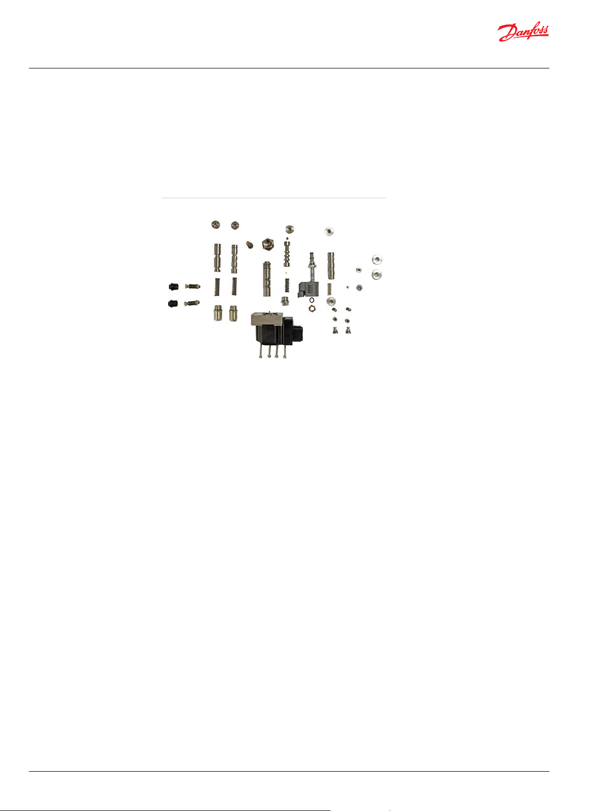
To properly maintain and clean the now fully dismantled EHi Steering Valve, follow these steps.
This task illustrates the basic procedures for examining, cleaning, and maintaining EHi Steering Valve.
1. Check your own parts against those pictured below.
All parts except housing are illustrated
Cleaning:
2. Clean all parts carefully in Shellsol K or similar cleaner fluid.
Inspection and replacement:
3. Replace all O-rings. Check all parts carefully for damage.
In case any part appears damaged, or in case disassembly of any part was difficult or impossible,
consider the EHi housing as damaged and replace the entire EHi valve.
22 | © Danfoss | Sep 2017 AX00000350en-US0101
Page 23

252
256
255
257
258
259
22
Service Manual
EHi Steering Valve
Assembly
Address seal kit
To assemble EHi Steering Valve, follow these steps.
Place EHi housing on holding tool.
Use 3 pcs M8 x 1.25, length: 10 mm + thickness of console plate.
EHi housing on holding tool
Insert steel plugs into ports
Place new O-rings from seal kit on plugs except on port plugs for which there are no seal rings/Orings available.
The seal kit contains plugs with O-rings, (16 and 20), so these plugs shall be replaced.
Plugs (2x82) with O-rings are present in dedicated spare part bag only, see Seal kits and spare parts for
EHi on page 9.
Steel plugs, parts, and housing
Wrench size and torque
Item Description Wrench size Torque
252 Plug 10 mm internal hex 45 ± 5 N•m [398.3 ± 44.3 lbf•in]
255 Plug 10 mm internal hex 45 ± 5 N•m [398.3 ± 44.3 lbf•in]
256 Plug 10 mm internal hex 45 ± 5 N•m [398.3 ± 44.3 lbf•in]
257 Plug with O-ring 8 mm internal hex 45 ± 5 N•m [398.3 ± 44.3 lbf•in]
258 Plug 6 mm internal hex 20 ± 3 N•m [177 ± 26.6 lbf•in]
©
Danfoss | Sep 2017 AX00000350en-US0101 | 23
Page 24

82
81
80
82
81
80
Service Manual
EHi Steering Valve
Assembly
Wrench size and torque (continued)
Item Description Wrench size Torque
22 Orifice, LS 3 mm internal hex 3.5 ± 0.5 N•m [31 ± 4.4 lbf•in]
259 Plug 6 mm internal hex 20 ± 3 N•m [177 ± 26.6 lbf•in]
1. Screw in the orifice (22) using a 3 mm Hex key.
Torque: 3.5 ± 0.5 N•m [31 ± 4.4 lbf•in]
If the EHi has steel plugs in ports:
2. In LS1-port: Screw in the plug (258) using a 6 mm Hex key.
Seal-ring is fitted to the plug.
Torque: 20 ± 3 N•m [177 ± 26.6 lbf•in]
3. In LS2-port: Screw in the plug (259) using a 6 mm Hex key.
Seal-ring is fitted to the plug.
Torque: 20 ± 3 N•m [177 ± 26.6 lbf•in]
4. In CF-side-port: Screw in the plug (257) using an 8 mm Hex key.
Seal-ring is fitted to the plug.
Torque: 45 ± 5 N•m [398.3 ± 44.3 lbf•in]
5. In T-side-port: Screw in the plug (256) using a 10 mm Hex key.
Seal-ring is fitted to the plug.
Torque: 45 ± 5 N•m [398.3 ± 44.3 lbf•in]
6. In P-side-port: Screw in the plug (255) using a 10 mm Hex key.
Seal-ring is fitted to the plug.
Torque: 45 ± 5 N•m [398.3 ± 44.3 lbf•in]
7. In EF-port: Screw in the plug (252) using a 10 mm Hex key.
Seal-ring is fitted to the plug.
Torque: 45 ± 5 N•m [398.3 ± 44.3 lbf•in]
Insert shock valves into housing
If EHi has shock valves:
EHi housing and shock valve components
24 | © Danfoss | Sep 2017 AX00000350en-US0101
Page 25

93
95.9
95.3
95.7
95.4
95.2
95.1
95.8
95.5
95.6
95.10
Service Manual
EHi Steering Valve
Assembly
Wrench size and torque
Item Description Wrench size Torque
82 (x2) Plug with O-ring 13 mm external hex 35 ± 3 N•m [309.8 ± 26.6 lbf•in]
1. Place the shock valves (80) with conical springs (81).
Conical springs affixed to shock valves for re-insertion.
2. Screw in the plugs (82) using a 13 mm socket spanner.
Torque: 35 ± 3 N•m [309.8 ± 26.6 lbf•in]
Insert pilot relief valve into housing
Pilot relief valve parts and housing
Wrench sizes and torque
Item Description Wrench size Torque
93 Plug 2 mm Screwdriver 95 PV valve cartridge Danfoss key (see below) 20 ± 3 N•m [14.8 ± 2.2 lbf•ft]
1. Place back up ring (95.5), O-rings (95.6, 95,7, 95.8), filter (95.10) and locking ring (95.9) in/on cartridge
(95.1).
2. Screw in cartridge (95) using special key.
Danfoss code 155L6494
20 ± 3 N•m [14.8 ± 2.2 lbf•ft]
After entire assembly of the steering valve, make the pressure setting on a test panel according to
valve setting specification, see Relief valve section.
3. Insert rubber protection plug (93).
©
Danfoss | Sep 2017 AX00000350en-US0101 | 25
Page 26
33.1
33.2
25.1
25.2
44.1
44.2
9.1
9.2
5.1
5.2
2
Service Manual
EHi Steering Valve
Assembly
Insert plugs near pilot relief valve into housing
Plugs and housing are shown
Wrench size and torque
Item Description Wrench size Torque
33 Plug with O-ring 8 mm internal hex 45 ± 5 N•m [398.3 ± 44.3 lbf•in]
44 Plug with O-ring 8 mm internal hex 45 ± 5 N•m [398.3 ± 44.3 lbf•in]
1. Place O-ring (44.2) on the plug (44.1).
2. Screw in the plug (44) using an 8 mm Hex key.
Torque: 45 ± 5 N•m [398.3 ± 44.3 lbf•in]
3. Place O-ring (33.2) on the plug (33.1).
4. Screw in the plug (33) using an 8 mm Hex key.
Torque: 45 ± 5 N•m [398.3 ± 44.3 lbf•in]
Insert directional valve into housing
Directional valve parts and housing
Wrench size and torque
Item Description Wrench size Torque
5 Plug with O-ring 32 mm external hex 45 ± 5 N•m [398.3 ± 44.3 lbf•in]
1. Insert the directional spool (2).
2. Place O-ring (5.2) on the plug (5.1).
3. Screw in the plug (5) using a 32 mm socket spanner.
45 ± 5 N•m [398.3 ± 44.3 lbf•in]
26 | © Danfoss | Sep 2017 AX00000350en-US0101
Page 27

33.1
33.2
25.1
25.2
44.1
44.2
9.1
9.2
13
14
15
16
17
18
19
20
Service Manual
EHi Steering Valve
Assembly
Insert plugs near directional valve into housing
Remaining two of four plugs nearby
Wrench size and torque
Item Description Wrench size Torque
9 Plug with O-ring 8 mm internal hex 45 ± 5 N•m [398.3 ± 44.3 lbf•in]
25 Plug with O-ring 8 mm internal hex 45 ± 5 N•m [398.3 ± 44.3 lbf•in]
1. Place O-ring (25.2) on the plug (25.1).
2. Screw in the plug (25) using an 8 mm Hex key.
Torque: 45 ± 5 N•m [398.3 ± 44.3 lbf•in]
3. Place O-ring (9.2) on the plug (9.1).
4. Screw in the plug (9) using an 8 mm Hex key.
Torque: 45 ± 5 N•m [398.3 ± 44.3 lbf•in]
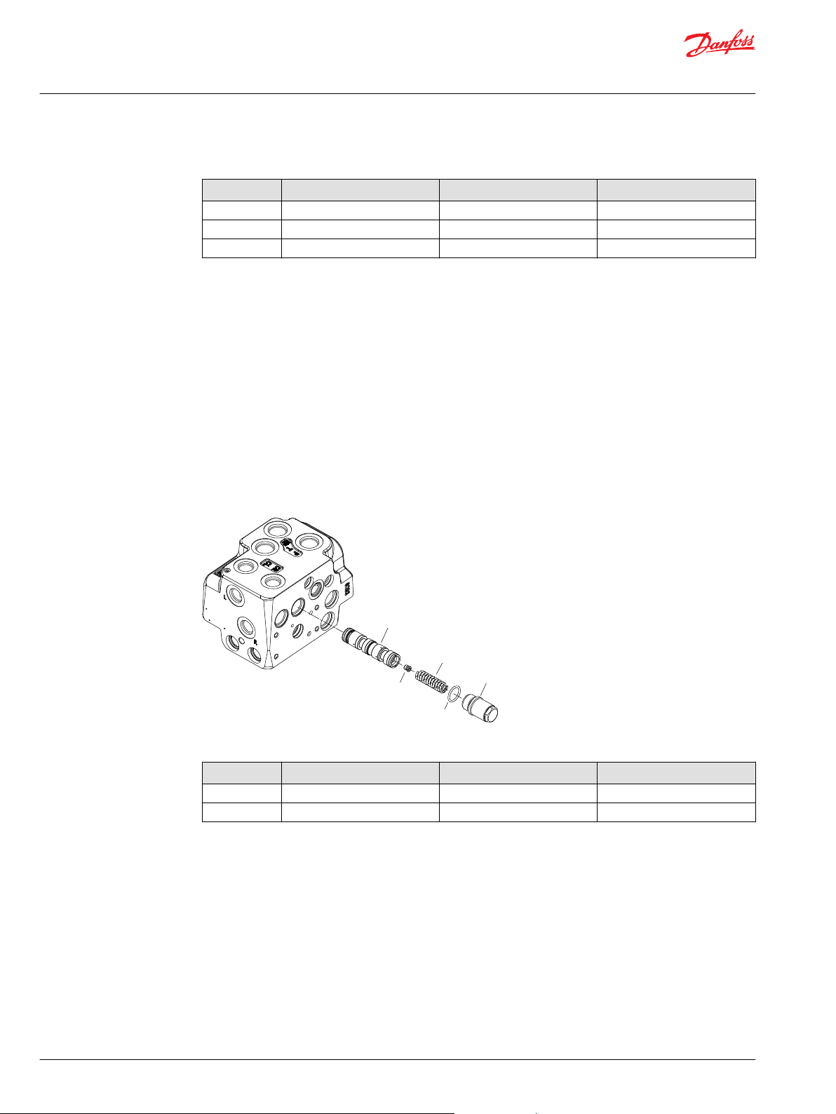
Insert pilot reduction valve(s) into housing
Insert the pilot reduction valve. item 13, 14, 15, and 16 are present in any EHi valve.
There may be two pilot reduction valves in some EHi models. If so, follow steps 5-8 as well.
Pilot reduction valve parts and housing.
Wrench size and torque
Item Description Wrench size Torque
16 Plug with O-ring 6 mm internal hex 30 ± 3 N•m [265.5 ± 26.6 lbf•in]
20 Plug with O-ring 6 mm internal hex 30 ± 3 N•m [265.5 ± 26.6 lbf•in]
1. Insert the spring (13).
©
Danfoss | Sep 2017 AX00000350en-US0101 | 27
2. Insert the cone (14).
Page 28

24.3
24.2
27.2
26
27.1
24.1
Service Manual
EHi Steering Valve
Assembly
3. Insert the spool (15).
4. Screw in the plug (16), using a 6 mm Hex key. O-ring is fitted on plug. Plug (16) with O-ring is included
in the seal kit for EHi.
Torque: 30 ± 3 N•m [265.5 ± 26.6 lbf•in]
5. Insert the spring (17).
6. Insert the cone (18).
7. Insert the spool (19).
8. Screw in the plug (20) using a 6 mm Hex key.
O-ring is fitted on plug.
Plug (20) with O-ring is included in the seak kit for EHi.
Torque: 30 ± 3 N•m [265.5 ± 26.6 lbf•in]
Insert PVFC/LS copy or LS shuttle valve into housing
If PVFC/LS copy valve is present, follow steps 1-4 below. Alternative to PVFC/LS copy valve can be LS
shuttle valve (88 and 87), in which case follow steps 5-7, below. Alternative to PVFC/LS copy valve or LS
shuttle valve can be no valves in this position at all. Then only plug (88) will be present. Screw in this plug
as described in step 7, below.
PVFC/LS copy valve parts and housing
Wrench size and torque
Item Description Wrench size Torque
27 Plug with O-ring 8 mm internal hex 45 ± 5 N•m [398.3 ± 44.3 lbf•in]
24.2 Check Valve - 1.4 ± 0.2 N•m [12.4 ± 1.8 lbf•in]
24.3 Check Valve - 1.4 ± 0.2 N•m [12.4 ± 1.8 lbf•in]
Some PVFC spools have check valves (24.2 and 24.3), which are screwed into spool (24.1).
1. Insert the PVFC spool (24)
2. Insert the spring (26).
3. Place O-ring (27.2) on the plug (27.1).
4. Screw in the plug (27) using an 8 mm Hex key.
Torque: 45 ± 5 N•m [398.3 ± 44.3 lbf•in]
28 | © Danfoss | Sep 2017 AX00000350en-US0101
Page 29
87.5
87.1
88
87.3
3.2
3.1
3.3
6
7.2
7.1
Service Manual
EHi Steering Valve
Assembly
LS Shuttle valve/plug and housing
Wrench size and torque
Item Description Wrench size Torque
88 Plug 5 mm internal hex 12.6 ± 0.6 N•m [111.5 ± 5.3
lbf•in]
87 LS Shuttle valve 5 mm internal hex 10 ± 1 N•m [88.5 ± 8.9 lbf•in]
5. Place O-rings (2x 87.3 and 1x 87.5) on the cartridge housing (87.1).
6. Screw in the cartridge (87) using a 5 mm Hex key.
Torque: 10 ± 1 N•m [88.5 ± 8.9 lbf•in]
7. Screw in the plug (88) using a 5 mm Hex key.
Seal-ring is fitted on plug. Plug (88) with seal-ring is included in the seal kit for EHi.
Torque: 12.6 ± 0.6 N•m [111.5 ± 5.3 lbf•in]
Insert priority valve into housing
If a priority valve is present, assemble the priority valve spool (3) with orifices. Before assembling orifices
(3.2) and (3.3) to the spool, fix the spool in a vice with aluminum jaws.
Priority valve parts and housing
©
Danfoss | Sep 2017 AX00000350en-US0101 | 29
Page 30
42.1
42.2
41
43.2
43.1
Service Manual
EHi Steering Valve
Assembly
Wrench size and torque
Insert cut off valve into housing
Item Description Wrench size Torque
7 Plug with O-ring 18 mm external hex 45 ± 5 N•m [398.3 ± 44.3 lbf•in]
3.2 Orifice, PP 3 mm internal hex 3.5 ± 0.5 N•m [31 ± 4.4 lbf•in]
3.3 Orifice, dynamic 2 mm internal hex 1 ± 0.1 N•m [8.9 ± 0.9 lbf•in]
1. Screw in the PP orifice (3.2) using a 3 mm Hex key.
Torque: 3.5 ± 0.5 N•m [31 ± 4.4 lbf•in]
2. If present: screw in the dynamic orifice (3.3) using a 2 mm Hex key.
Torque: 1 ± 0.1 N•m [8.9 ± 0.9 lbf•in]
3. Insert the priority valve spool (3) with the spring bore pointing outwards.
4. Insert the spring (6).
5. Place O-ring (7.2) on the plug (7.1).
6. Screw in the plug (7) using an 8 mm Hex key.
Torque: 45 ± 5 N•m [398.3 ± 44.3 lbf•in]
Cut off valve parts and housing
Wrench size and torque
Item Description Wrench size Torque
43 Plug with O-ring 18 mm external hex 45 ± 5 N•m [398.3 ± 44.3 lbf•in]
42.2 Plug 3 mm internal hex 3.5 ± 0.5 N•m [31 ± 4.4 lbf•in]
1. If cut off spool (42) has plug (42.2), screw in the plug using a 3 mm Hex key and multi grip pliers.
3.5 ± 0.5 N•m [31 ± 4.4 lbf•in]
2. Insert the cut off spool (42) with the spring bore pointing outwards.
3. Place O-ring (43.2) on the plug (43.1).
4. Insert the spring (41) in the plug (43).
5. Screw in the plug (43) using an 18 mm socket spanner.
Torque: 45 ± 5 N•m [398.3 ± 44.3 lbf•in]
Insert reaction switch valve (RSV) into housing
If RSV is present:
30 | © Danfoss | Sep 2017 AX00000350en-US0101
Page 31
30
31
32.2
32.1
46.4
46.3
46.2
46.1
47
48
49
Service Manual
EHi Steering Valve
Assembly
RSV parts and housing
Wrench size and torque
Item Description Wrench size Torque
32 Plug with O-ring 18 mm external hex 45 ± 5 N•m [398.3 ± 44.3 lbf•in]
1. Insert RSV spool (30) with the spring bore pointing outwards.
2. Place O-ring (32.2) on the plug (32.1).
3. Insert the spring (31) in the plug (32).
4. Screw in the plug (32) using an 18 mm socket spanner.
Torque: 45 ± 5 N•m [398.3 ± 44.3 lbf•in]
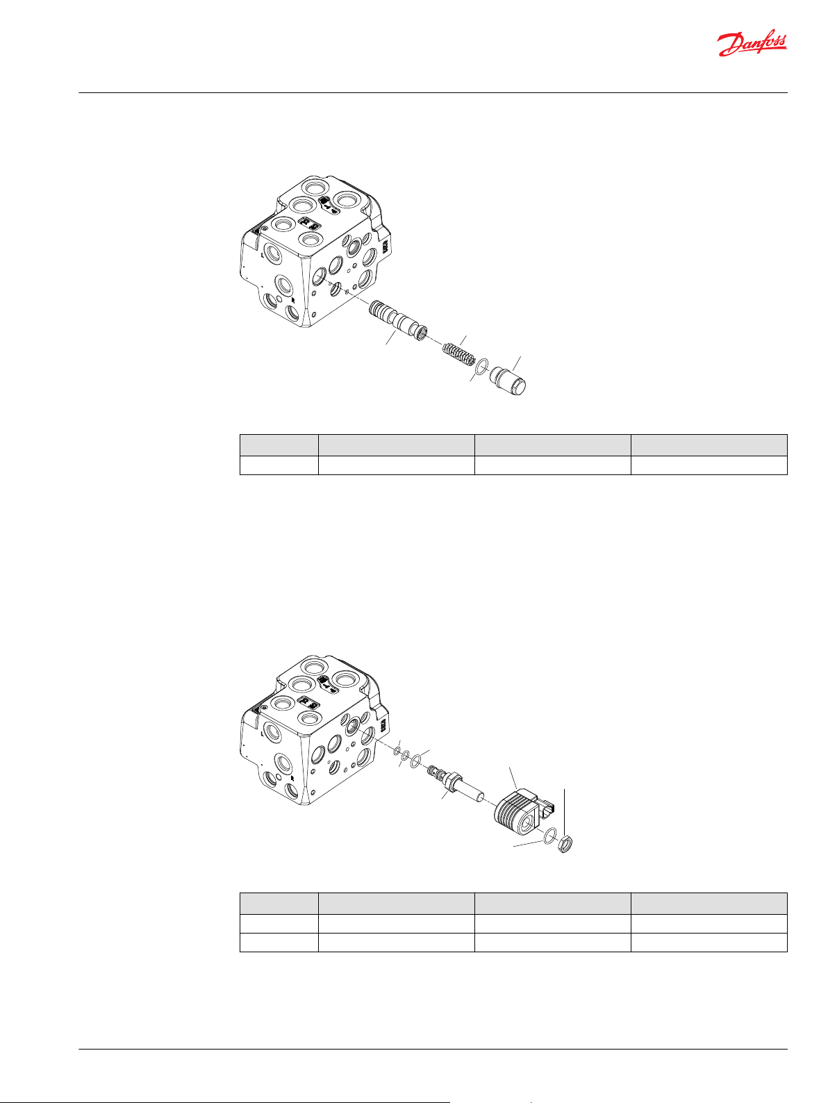
Attach coil to housing
Coil parts and EHi housing
Wrench size and torque
Item Description Wrench size Torque
48 Nut 19 mm external hex 5 ± 1 N•m [44.3 ± 8.9 lbf•in]
46.1 Spool, pilot dump 7/8 inch external hex 15 ± 2 N•m [132.8 ± 17.7 lbf•in]
1. Place O-rings (46.2, 46.3, and 46.4) on spool (46.1).
©
Danfoss | Sep 2017 AX00000350en-US0101 | 31
2. Screw in the cartridge spool (46) using a 7/8 inch ring spanner or long socket spanner.
Torque: 15 ± 2 N•m [132.8 ± 17.7 lbf•in]
Page 32

4.13
4.12
4.11
10
4.9
4.1
Service Manual
EHi Steering Valve
Assembly
Attach PVE to housing
3. Place the coil (47).
4. Place the O-ring (49).
5. Screw on the nut (48) using a 19 mm socket spanner.
Torque: 5 ± 1 N•m [44.3 ± 8.9 lbf•in]
PVE parts and housing
Wrench size and torque
Item Description Wrench Size Torque
10 (x4) Screw 5 mm internal hex 8 ± 1 N•m [70.8 ± 8.9 lbf•in]
1. Check proper movement of EH spool (2): press on spool end, the spool must be able to be moved
downwards 4 mm with force < 100N [22.48 lbf], and it must be able to return to starting position by
help of the neutral spring package integrated in the spool end facing plug (2).
Press on spool end
32 | © Danfoss | Sep 2017 AX00000350en-US0101
Page 33

Service Manual
EHi Steering Valve
Assembly
2. Place O-rings (4.11, 4.12, 4.13) and filter (4.9) on PVE (4.1).
Place O-rings on PVE
3. Place the PVE(4) on EHi housing and screw in the four screws for the PVE (10) using a 5 mm Hex key.
8 ± 1 N•m [70.8 ± 8.9 lbf•in]
4. Make test and valve settings according to description in the following pages.
5. Screw in plastic plugs to the connections ports to keep the ports clean during storage and
transportation.
Steel plugs in EHi ports
©
Danfoss | Sep 2017 AX00000350en-US0101 | 33
Page 34

EHi
PVE
SOL
RSV
COV
Electronics
Shock
Suction
EH Valve
CL
CR
PVFC
RV
PRV
13 BAR
PRV
13 BAR
PE
TE
CF
P
LS1
LS2
T
PRIO
P EF
T
CL
CR
P LS T
OSPC LSR
L R
R
L
1818
Service Manual
EHi Steering Valve
Testing of EHi
This section describes minimum tests needed, when the EHi steering valve has been disassembled and
reassembled.
Example of system setup: EHi5, Load Sensing Reaction to be used with OSPC LSR type steering unit:
Setup for testing
Use universal hydraulic work bench with pump capacity:
40 l/min [10.6 gal/min] and up to 280 bar [4061 PSI] pressure for relief valve setting and steering test.
34 | © Danfoss | Sep 2017 AX00000350en-US0101
Page 35

Service Manual
EHi Steering Valve
Testing of EHi
EHi for LS steering units
The hydraulic oil must be with a viscosity of 21 cSt. at 50°C [122°F] and with maximum degree of
contamination according to ISO 4406: 21/19/16.
Description for system setup, when priority valve is integrated in EHi and when EHi is configured to be
used with LS type steering unit (as illustrated in system diagram above, EHi5):
1. Connect double rod cylinder to CL and CR ports of EHi.
2. Connect front T and EF port of EHi to tank of pump station.
3. Connect the front P port of EHi to P port from pump.
4. Connect the side P port of EHi to P port of LS steering unit.
5. LS1 of EHi:
a) When using pump station with fixed gear pump: Plug LS1 with steel plug
b) With LS pump in pump station: connect LS1 of EHi to LS of pump.
6. LS2 of EHi (is only present in EHi's with PVFC spool to be used for dynamic type steering units):
connect LS2 to LS port of OSP steering unit. LS dynamic flow will stream out of LS2 port of EHi, and
must be able to pass on to tank.
7. Connect side T of EHi to T port of OSP.
8. Connect L and R of EHi to L and R of OSP.
9. Connect pressure gauges to all ports of EHi.
10. Connect voltage supply and signal input for the PVE.
T pressure should not exceed ~5 bar [73 PSI]. Maximum allowed T pressure is 25 bar [363 PSI].
Pump supply circuit must be adjusted not to exceed 280 bar [4061 PSI] P-T.
In case the EHi has no RSV the OSP steering unit can be omitted from the tests.
©
Danfoss | Sep 2017 AX00000350en-US0101 | 35
Page 36

EHi
SOL
RSV
COV
EH Valve
Electronics
Shock
Suction
PE
TE
PRV
13 BAR
PRV
13 BAR
PVFC
RV
PRIO
P
LS1
LS2
P
EF T
CL
CR
P
T
OSPC OR
L
R
CL CR
R
L
PVE
18
18
Service Manual
EHi Steering Valve
Testing of EHi
EHi for open center steering units
Description for system setup, when priority valve is integrated in EHi and when EHi is configured to be
used with open center type steering unit (as illustrated in system diagram, EHi2).
Example of system setup: EHi2, Open center Reaction to be used with OSPC OR type steering unit:
1. Connect double rod cylinder to CL and CR ports of EHi.
2. Connect T port of EHi to tank of pump station.
3. Connect the front P port of EHi to P port from pump. Plug the side P port of EHi.
4. Connect EF port of EHi to P port of OSP steering unit.
5. LS1 of EHi to be plugged (only gear pump or pump providing fixed flow can be used for this EHi
system)
6. LS2 of EHi to be plugged.
7. Connect side T of EHi to T port of OSP.
36 | © Danfoss | Sep 2017 AX00000350en-US0101
Page 37

Service Manual
EHi Steering Valve
Testing of EHi
8. Connect L and R of EHi to L and R of OSP.
9. Connect pressure gauges to all ports of EHi.
10. Connect voltage supply and signal input for the PVE.
In case the EHi has no RSV the OSP steering unit can be omitted from the tests.
For EHi without integrated priority valve and with fixed gear pump in pump station, use external
priority valves:
For dynamic systems (when PVFC is present in EHi): Use Danfoss priority valve OLS 80 Code
•
152B8269, or other OLS 80 with same orifice and spring specification. Dynamic orifice: Ø1.0 mm.
LS orifice: Ø1.2 mm. Spring: 7 bar [102 PSI].
For static systems (when PVFC is not present in EHi): Use Danfoss priority valve OLS 80 code
•
152B0263, or other OLS 80 with same spring specification: 10 bar [145 PSI].
©
Danfoss | Sep 2017 AX00000350en-US0101 | 37
Page 38

Service Manual
EHi Steering Valve
Steering tests
Start up test
Apply battery power and input signal to the PVE.
With PVED CLS: The coil must be connected to and actuated by the PVED CLS.
•
With other PVE's: connect DC voltage and ground to the coil (12V or 24V depending on voltage
•
marking on the coil).
During the testing no disturbing vibrations, noise, or other irregularities must occur.
1. Start the pump, the pump flow is adjusted to approximately 25 l/min and pump pressure control
must be set to approximately 70 bar [1015 PSI].
2. Let the supplied oil flow through the steering valve for a few minutes. Then actuate the PVE a few
times in both directions to bleed of air from the EHi and the system. Observe that the steering
cylinder is moving according to direction of input signal for PVE.
3. Operate the PVE to move the steering cylinder from end stroke to end stroke for at least 5 cycles.
Make sure pressure P-T, 70 bar [1015 PSI] can be achieved, when steering against end stroke. If this is
not possible, the adjusting screw of the pilot relief valve (item 95 of exploded view) must be turned
clockwise until P-T, 70 bar [1015 PSI] is achievable.
Pilot relief valve
Neutral positioning test
Cut off valve test
1. The pump flow is adjusted to approximately 25 l/min [6.6 gal/min] and pressure to max 280 bar [4061
PSI].
2. Steer the cylinder to an end stroke, keep input signal on PVE for full spool travel.
3. The pilot relief valve (item 95 of exploded view) is set according to specification:
Maximum steering pressure (P-T), bar, for the code in question.
The setting pressure is the pressure on the P-port minus the T-port of EHi.
1. Apply input signal to the PVE to make a cylinder movement.
2. Remove input signal to the PVE, the steering valve must be able to go to neutral later than ~1 second:
cylinder movement must stop.
3. The EHi is proper in neutral position when the pressure drop (LS1-T of EHi) is no higher than 10 bar
[145 PSI] at pump flow 25 l/min [6.6 gal/min], and there must be no movement of the steering
cylinder.
The cut off valve spool movement can be controlled by:
1. With electric power on coil and on PVE and with signal on PVE, the steering cylinder must move to
end stroke and maximum steering pressure must be build up.
2. Steer in opposite direction to observe cylinder movement.
3. While cylinder is moving, remove electric power to the coil (keep battery power and signal to PVE):
cylinder movement must stop and pressure (LS1-T of EHi) must drop to be no higher than 10 bar [145
PSI].
RSV valve test
If the EHi is equipped with an RSV valve, spool movement can be controlled by:
38 | © Danfoss | Sep 2017 AX00000350en-US0101
Page 39

Service Manual
EHi Steering Valve
Steering tests
1. With electric power on coil and on PVE and with signal on PVE, the steering cylinder must move to
end stroke and maximum steering pressure must be build up.
2. Steer in opposite direction to observe cylinder movement. Apply input for slow movement of
cylinder, < 25% of max. signal.
3. Activate steering wheel to steer in opposite direction as movement of cylinder: cylinder movement
speed shall decrease/change to opposite direction dependent on steering wheel speed. Steering
wheel torque must not exceed 10 N•m [88.5 lbf•in], when cylinder moves inside end strokes.
©
Danfoss | Sep 2017 AX00000350en-US0101 | 39
Page 40

Service Manual
EHi Steering Valve
Check for external leakage
1. Remove the port connections, after testing the former items.
2. 2xP, CF, LS1, LS2, T-side, EF, L, R, CL and RL ports are to be plugged w. steel plugs.
3. Oil pressure of 20 bar [290 PSI] is supplied to the T-front port for approx. 3 minutes: No leakage must
be found in any assemblies.
40 | © Danfoss | Sep 2017 AX00000350en-US0101
Page 41

Service Manual
EHi Steering Valve
Shock valves
If the EHi is equipped with shock valves, these are preset and locked in setting from factory. Solely no
adjustments can be made on these valves.
©
Danfoss | Sep 2017 AX00000350en-US0101 | 41
Page 42
Service Manual
EHi Steering Valve
Tightening torques for connections
Tightening torques for connections EHi
Connections Maximum tightening torque N•m [lbf•in]
M12 • 1.5 30 [265] 20 [177] 30 [265] 25 [221]
M18 • 1.5 80 [708] 55 [486] 70 [619] 50 [442]
M22 • 1.5 100 [885] 65 [575] 80 [708] 60 [531]
With cutting edge With copper washer With alum. washer O-ring
42 | © Danfoss | Sep 2017 AX00000350en-US0101
Page 43

Service Manual
EHi Steering Valve
©
Danfoss | Sep 2017 AX00000350en-US0101 | 43
Page 44

Danfoss
Power Solutions GmbH & Co. OHG
Krokamp 35
D-24539 Neumünster, Germany
Phone: +49 4321 871 0
Danfoss
Power Solutions ApS
Nordborgvej 81
DK-6430 Nordborg, Denmark
Phone: +45 7488 2222
Danfoss
Power Solutions (US) Company
2800 East 13th Street
Ames, IA 50010, USA
Phone: +1 515 239 6000
Danfoss
Power Solutions Trading
(Shanghai) Co., Ltd.
Building #22, No. 1000 Jin Hai Rd
Jin Qiao, Pudong New District
Shanghai, China 201206
Phone: +86 21 3418 5200
Products we offer:
Comatrol
www.comatrol.com
Turolla
www.turollaocg.com
Hydro-Gear
www.hydro-gear.com
Daikin-Sauer-Danfoss
www.daikin-sauer-danfoss.com
Bent Axis Motors
•
Closed Circuit Axial Piston
•
Pumps and Motors
Displays
•
Electrohydraulic Power
•
Steering
Electrohydraulics
•
Hydraulic Power Steering
•
Integrated Systems
•
Joysticks and Control
•
Handles
Microcontrollers and
•
Software
Open Circuit Axial Piston
•
Pumps
Orbital Motors
•
PLUS+1® GUIDE
•
Proportional Valves
•
Sensors
•
Steering
•
Transit Mixer Drives
•
Danfoss Power Solutions is a global manufacturer and supplier of high-quality hydraulic and
electronic components. We specialize in providing state-of-the-art technology and solutions
that excel in the harsh operating conditions of the mobile off-highway market. Building on
our extensive applications expertise, we work closely with our customers to ensure
exceptional performance for a broad range of off-highway vehicles.
We help OEMs around the world speed up system development, reduce costs and bring
vehicles to market faster.
Danfoss – Your Strongest Partner in Mobile Hydraulics.
Go to www.powersolutions.danfoss.com for further product information.
Wherever off-highway vehicles are at work, so is Danfoss. We offer expert worldwide support
for our customers, ensuring the best possible solutions for outstanding performance. And
with an extensive network of Global Service Partners, we also provide comprehensive global
service for all of our components.
Please contact the Danfoss Power Solution representative nearest you.
Local address:
Danfoss can accept no responsibility for possible errors in catalogues, brochures and other printed material. Danfoss reserves the right to alter its products without notice. This also applies to products
already on order provided that such alterations can be made without changes being necessary in specifications already agreed.
All trademarks in this material are property of the respective companies. Danfoss and the Danfoss logotype are trademarks of Danfoss A/S. All rights reserved.
©
Danfoss | Sep 2017 AX00000350en-US0101
 Loading...