

Danfoss Edelstahl Verteilersysteme, Stainless Steel Distribution Systems Operating guide [de]
Page 1
Montage- und Betriebsanleitung / Mounting and Installation Guide
Edelstahl Verteilersysteme
(für VX-F) / Stainless Steel
Distribution Systems (for VX-F)
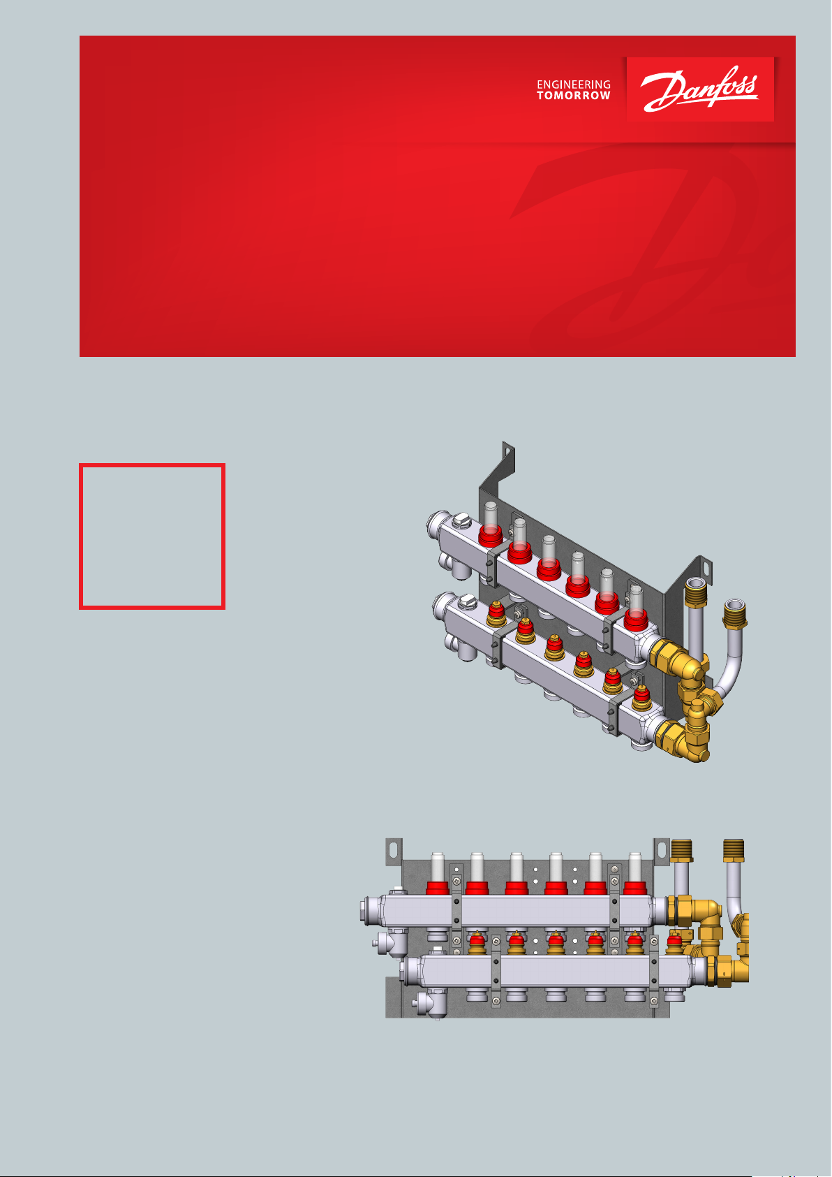
Danfoss vorgefertigte Edelstahl Verteilersysteme für Fussbodenheizung / Danfoss prefabricated solutions for floor heating
Plug & Play
Verteilersysteme /
Plug & Play
distribution systems
für VX-F
Page 2
Montageanleitung / Installation Guide Edelstahl Verteilersystem für VX-F/ Stainless steel distribution system for VX-F
Verteilersystem für VX-F Station
Distribution unit for VX-F units
1. INHALT / CONTENT
1.0 Inhalt / Content ........................................................................................................................................................................................................................2
2.0 Anschluss, Sicherheit, Handhabung / Connection, Safety, Handling ...................................................................................................................3
3.0 Installationsanleitung generell / Installation instructions, general .......................................................................................................................5
4.0 Produkt Introduktion / Product introduction ................................................................................................................................................................6
5.0 Hauptkomponente & Anschluss / Main components & Connection....................................................................................................................8
6.0 Montage / Mounting ........................................................................................................................................................................................................... 10
7.0 Montage in Einbauschrank / Mounting in recess box .............................................................................................................................................11
8.0 Einstellung und Inbetriebnahme / Adjustment and commissioning ................................................................................................................ 14
9.0 Regeltechnik - Fussbodenheizung / Control - Floor heating ................................................................................................................................ 16
10.0 Wartung / Maintenance ..................................................................................................................................................................................................... 18
11.0 EU Gutachten / EU Declaration of Conformity ........................................................................................................................................................... 19
12.0 Inbetriebnahmezertifikat / Commissioning Certificate .......................................................................................................................................... 20
2 | © Danfoss | Produced by Danfoss Redan A/S | 2016.12
VI.LZ.O1.5B
Page 3
Montageanleitung / Installation Guide Edelstahl Verteilersystem für VX-F/ Stainless steel distribution system for VX-F
2. ANSCHLUSS, SICHERHEIT, HANDHABUNG / CONNECTION, SAFETY, HANDLING
GERMAN - DE
Anleitung
Bitte lesen Sie diese Anleitung vor der Installation und Inbetriebnahme des Verteilersystems sorgfältig durch. Der Hersteller übernimmt keine Haftung für Ausfälle oder Schäden, die durch das
Nichtbeachten der Hinweise in dieser Betriebsanleitung entstehen.
Lesen und befolgen Sie sämtliche Anweisungen, um Verletzungen
und/oder Sachschäden zu vermeiden. Das Überschreiten der empfohlenen Betriebsparameter erhöht beträchtlich das Risiko für Verletzungen und/oder Sachschäden.
Die Einbau-, Inbetriebnahme- und Wartungsarbeiten müssen von
(für Heizungs- und Anschlussarbeiten) qualifiziertem und autorisiertem Personal durchgeführt werden.
Sobald die Station eingebaut ist und sich in Betrieb befindet, besteht in der Regel keine Notwendigkeit, die Einstellungen oder andere
Funktionen zu verändern. Das Verteilersystem ist sehr betriebssicher und einfach zu bedienen.
Energiequelle
Das Verteilersystem ist in erster Linie für den Anschluss an eine
Fernwärmequelle ausgelegt. Alternative Energiequellen können
verwendet werden, wenn die Betriebsbedingungen zu jeder Zeit
derjenigen der Fernwärme entsprechen.
Anwendung
Die Danfoss Edelstahl Verteilersysteme sind vorgefertigte
Heizkreisverteiler für Fußbodenheizung, die für den separaten
Einbau oder für die Montage zusammen mit den b ekannten Danfoss
Wohnungsstationen vorbereitet sind.
Werkstoffauswahl
Verwenden Sie nur Werkstoffe, die den lokalen Vorschriften entsprechen.
Korrosion
Der maximale Chlorgehalt des Mediums darf nicht mehr als 300
mg/l betragen. Wenn der empfohlene Chlorgehalt überschritten
wird, steigt das Korrosionsrisiko beträchtlich.
Lagerung und Handhabung
Vor dem Einbau muss/müssen die Verteilersystem(e) in einem trockenen und beheizten (d. h. frostfreien) Raum gelagert werden.
(Relative Luftfeuchtigkeit max. 80 % und Lagertemperatur 5–70 °C).
Die Verteilersysteme dürfen nicht höher als im Werk gestapelt
werden. Verteilersysteme, die in Kartons geliefert werden, müssen
an den Handgriffen der Verpackung angehoben werden. Zum Transportieren/Befördern über große Entfernungen müssen die Verteilersysteme auf Paletten platziert werden.
Heben Sie die Verteilersysteme nach Möglichkeit nicht an den Rohren
an, da dadurch Leckagen entstehen können.
ZIEHEN Sie die Anschlüsse nach dem Transport erneut FEST.
Entsorgung
Die Verteilersysteme bestehen aus Materialien, die nicht zusammen
mit dem Hausmüll entsorgt werden dürfen. Die gesammte Energieversorgung unterbrechen und bitte zerlegen Sie das Produkt zur
entsorgung in Einzelteile und führen Sie sie gemäß den geltenden
örtlichen Vorschriften sortenrein der Entsorgung zu.
Anschluss
Eine Unterbrechung der gesamten Energieversorung zu der Station
muss jederzeit möglich sein, (hierunter auch Stromzufuhr).
Potentialausgleich / Erdung
Unter Potentialausgleich versteht man alle Maßnahmen zum Beseitigen elektrischer Potentialunterschiede (Kontaktspannungen),
die zwischen z.B zwei Rohrleitungen auftreten können. Der Potentialausgleich ist eine wichtige Maßnahme zum Schutz gegen elektrischen
Schlag. Potentialausgleich reduziert Korrosion im Wärmetauscher,
Durchlauferhitzer, Fernwärmestationen und Sanitärinstallationen.
Potentialausgleich sollte nach den Bestimmungen 60364-4-41: 2007
und IEC 60364-5-54: 2011 erfolgen.
Bindungsstelle ist mit einem Erdungssymbol auf der rechten unteren
Ecke der Montageplatte markiert und es gibt ein Loch in der Montageplatte und ein Etikett mit Erdungssymbol.
Warnung! Heiße Oberflächen
Einige Teile des Verteilersystems können sehr heiß werden und Verbrennungen verursachen. Seien Sie sehr vorsichtig, wenn Sie sich in
der direkten Umgebung der Station befinden.
Notfälle
Im Falle von Feuer, Leckagen oder sonstigen Gefahren, sind, wenn
möglich, alle Energieversorgungsanschlüsse des Verteilersystems
zu schließen. Zudem ist Abhilfe durch professionelle Fachkräfte zu
schaffen.
Warnung vor Transportschäden
Beim Erhalt und vor dem Einbau ist das Verteilersystem auf eventuelle
Transportschäden zu prüfen. Das Verteilersystem ist mit größter Vorsicht und Sorgfalt zu bewegen und zu bedienen.
Hinweis – Festziehen der Anschlüsse
Vor dem Befüllen der Fernwärmestation mit Wasser sind ALLE Rohrleitungsanschlüsse festzuziehen, da sie von Vibrationen während
des Transports möglicherweise gelocker t wurden und Leckagen entstanden sind. Sobald die Fernwärmestation befüllt wurde und warm
ist, sind ALLE Rohrleitungsanschlüsse erneut festzuziehen.
ZIEHEN SIE DIE ROHRLEITUNGSANSCHLÜSSE NICHT ZU FEST AN .
Handhabung
Wir empfehlen, beim Handhaben und Einbauen der Fernwärmestation geeignetes und sicheres Schuhwerk zu tragen.
Bitte bemerken: Eingriffe und Nacharbeiten an unseren
Komponenten führen zum Verlust der Gewährleistung.
VI.LZ.O1.5B
© Danfoss | Produced by Danfoss Redan A/S | 2016.12 | 3
Page 4

Montageanleitung / Installation Guide Edelstahl Verteilersystem für VX-F/ Stainless steel distribution system for VX-F
2. ANSCHLUSS, SICHERHEIT, HANDHABUNG / CONNECTION, SAFETY, HANDLING
ENGLISH - GB
Instructions
Please read these instructions carefully before installing and commissioning this unit. The manufacturer accepts no liability for loss
or damage resulting from failure to comply with these instructions
for use. Read and follow these instructions carefully to prevent the
risk of physical injury and/or damage to property. Exceeding the
recommended operating parameters appreciably increases the risk
of personal injury and/or damage to property.
Installation, commissioning and maintenance must be carried out
by qualified and authorised personnel (both plumbing and electrical work).
Once the system has been installed and is operating, there is normally
no need to alter the settings or other functions. The distribution
system unit is very reliable and easy to operate.
Heat source
The distribution system is primarily designed for connection to district heating. Alternative energy sources can be used if the operating
conditions are equivalent to district heating at all times.
Application
The Danfoss stainless steel distribution systems are prefabricated
solutions for floor heating, which can be installed separately or be
implemented with the Danfoss flat station range, in connection with
a boiler or as an extension of an existing heating system.
Choise of materials
Only use materials that comply with local regulations.
Potential equalization/grounding
Potential equalization is an electrical equalizer connection to secure
against user contact with dangerous voltage, which may occur for
example between two piping systems. Potential equalization reduces corrosion in heat exchangers, water heaters, district heating
units and plumbing installations.
Potential bonding should be carried out according to 60364-4-41:
2007 and IEC 60364-5-54: 2011.
Bonding poing is marked on the mounting plate below right corner
with an earthing symbol and there will be a hole in the station mounting plate and a label with earth symbol.
Warning! Hot surfaces
Parts of the unit may be very hot and can cause burn injuries.
Be very careful when you are in the immediate vicinity of the unit
Emergencies
In the event of fire, leaks or other hazards, immediately shut off all
sources of energy to the unit, if possible, and call for appropriate
assistance.
If the domestic hot water is discoloured or malodorous, shut off
all ball valves on the unit notify all users and call for professional
assistance without delay.
Warning about damage during transport
On reception of the unit, and before installing it, check for any evidence of damage during transport.
The unit must be handled and moved with the greatest care and
attention.
Corrosion
The maximum chlorine content of the medium must not be higher
than 300 mg/l. The risk of corrosion increases considerably if the
recommended chlorine content is exceeded.
Storage
Before installation, the unit(s) must be stored in a dry, heated (i.e.
frostfree) room.
(Relative humidity max. 80% and storage temp. 5–70°C).
The units must not be stacked higher than the limit at the factory.
Units supplied in cardboard packaging must be lifted using the handles incorporated in the packaging. Units must be placed on pallets
for transport/moving across large distances.
As far as possible, do not lift the unit by the pipes.
Retighten ALL pipe connections after transport/moving.
Disposal
Dispose of the packaging in accordance with the local regulations for
disposal of used packaging materials. The unit is made of materials
that cannot be disposed of together with household waste.
Close all energy sources and disconnect all connection pipes. Disconnect and dismantle the product for disposal in accordance with
the applicable local regulations for the disposal of the individual
components.
Connection
It must be possible to cut off all energy sources to the system – including electrical connections – at all times.
NB! - Tightening of connections
Before filling the unit with water, ALL pipe connections MUST be
retightened, as vibrations during transport may have caused leaks.
Once the unit has been filled and the system is hot, ALL pipe connections MUST be retightened once more. DO NOT OVERTIGHTEN THE
PIPE CONNECTIONS.
Handling
We recommend that you wear suitable safety footwear while
handling and installing the unit.
Please note: Eingriffe und Nacharbeiten an unseren
Komponenten führen zum Verlust der Gewährleistung.
4 | © Danfoss | Produced by Danfoss Redan A/S | 2016.12
VI.LZ.O1.5B
Page 5
Montageanleitung / Installation Guide Edelstahl Verteilersystem für VX-F/ Stainless steel distribution system for VX-F
3. INSTALLATIONSANLEITUNG GENERELL / INSTALLATION INSTRUCTIONS, GENERAL
GERMAN - DE ENGLISH - GB
Generell
Die Einbau-, Anschluss- und Wartungsarbeiten bei dem System dürfen nur von qualifiziertem und autorisiertem Personal durchgeführt
werden. Der Einbau muss immer gemäß den geltenden Vorschriften
und in Übereinstimmung mit dieser Anleitung erfolgen.
Das System muss so eingebaut werden, dass sie frei zugänglich ist
und ohne unnötige Unterbrechungen gewartet werden kann. Heben Sie das Verteilersystem an der Montage-/Rückplatte an. Befestigen Sie ihn dann an einer stabilen Wand oder in den Einbauschrank,
indem Sie vier robuste Bolzen, Schrauben oder Spannbolzen in die
vier Bohrlöchern in der Montage-/Rückplatte einsetzen und diese
festziehen.
Spülen Sie vor der Inbetriebnahme die Hausverrohrung gründlich
durch, um Verunreinigungen zu entfernen. Prüfen und Reinigen Sie
auch die Schmutzfänger in der Fernwärmestation.
Prüfung und Anschlüsse
Ziehen Sie vor dem Befüllen des Systems mit Wasser erneut alle
Rohrleitungsanschlüsse fest, da sie von Vibrationen und Erschütterungen während des Transports möglicherweise gelockert wurden und Leckagen entstanden sind. Ziehen Sie, sobald das System
mit Wasser gefüllt wurde, die Rohrleitungsanschlüsse erneut fest,
bevor Druckprüfungen zur Erkennung von Leckagen durchgeführt
werden. Prüfen Sie nach der Erwärmung des Systems alle Anschlüsse
und ziehen Sie sie, sofern erforderlich, erneut fest.
Bitte beachten Sie, dass die Anschlüsse EPDM-Dichtungen aufweisen können.
Überwurfmuttern NICHT ZU FEST
Überwurfmuttern können zu Leckagen führen.
zu fest angezogene Überwurfmuttern oder durch das Versäumnis
schlüsse erneut festzuziehen, entstanden sind, fallen nicht unter die
Gewährleistung.
Aus diesem Grund ist es wichtig, dass Sie die
ANZIEHEN. Zu fest angezogene
Leckagen, die durch
, An-
General
The installation, connection and maintenance of the system must be
performed by qualified and authorised personnel. Installation must
always be performed in accordance with the applicable legislation
and in compliance with these instructions.
The system must be installed so that it is freely accessible and can be
maintained without unnecessary disruption. Lift the unit by its
mounting plate/rear section (to maximum extent do not lift the
unit by the pipes) and secure it to a solid wall or in the recess box using 4 expansion bolts or the like positioned in the two bore holes in
the mounting plate. It is recommended that at least two people are
involved in the installation.
Before commissioning, rinse all the pipes in the household piping
system thoroughly to remove any impurities, and check and clean
the dirt strainers in the unit.
Test and connections
Before filling the system with water, retighten all the pipe connections
because vibrations and shocks during transport and handling may
have caused leaks. Once the system has been filled with water, tighten
all the pipe connections once more before performing pressure test
for leaks. After heating of the system, check all the connections and
retighten if necessary.
Please note that the connections may feature EPDM rubber gaskets!
Therefore, it is important that you DO NOT OVERTIGHTEN the union
nuts. Overtightening may result in leaks.
Leaks caused by overtightening or failure to retighten connections
are not covered by the warranty.
VI.LZ.O1.5B
© Danfoss | Produced by Danfoss Redan A/S | 2016.12 | 5
Page 6

Montageanleitung / Installation Guide Edelstahl Verteilersystem für VX-F/ Stainless steel distribution system for VX-F
4. PRODUKT INTRODUKTION / PRODUCT INTRODUKTION
GERMAN - DE ENGLISH - GB
Die Danfoss Edelstahl Verteilersysteme sind vorgefertigte
Heizkreisverteiler für Fußbodenheizung, die für den separaten Einbau oder für die Montage zusammen mit den bekannten Danfoss
Wohnungsstationen Type VX-F vorbereitet sind.
Durch diese Plug & Play Konstruktionder Fußbodenverteiler können
die Montagezeiten bei der Hausinstallation erheblich verkürzt
werden.
Die Systeme sind als Standardlösungen von 3 bis 12 Heizkreise
erhältlich und beinhalten alle einem Endstück mit manueller
Entlüftung und Entleerung.
The Danfoss stainless steel distribution systems are prefabricated
solutions for floor heating, which can be installed separately or be
implemented with the Danfoss VX-F flat station range.
These solutions make it easier for the installer to order a ready-made
plug & play construction for mounting of distribution pipes for the
building section.
The systems are available as standard solutions with 3 to 12 connections
and include manual air vent and drain valve.
In addition the solutions include a flow meter to maintain the
designated flow rate.
Zusätzlich enthalten die Lösungen einen Durchflussmesser zur
Aufrechterhaltung der bestimmten Durchflussrate.
Die Verteilersysteme können mit fest verdrahtetem Heizkreisregler
FH-WC 230 V und Thermo-Motoren TWA-A NC gemäß Anzahl der
Heizkreise versehen verden.
Die Systeme können in Unterputzausführung mit Einbauschrank
oder in Aufputzausführung montiert werden.
Einbauschränke für Unterputzmontage sind in zwei Größen erhältlich
- H1350/B690/T150 mm und 1350/B850/T150 mm. Breite 690 mm
passt zu Verteilersystemen mit bis zu 7 Heizkreisen und Breite 850
mm passt zu Verteilersystemen mit 7 bis 11 Heizkreisen.
Ein Kugelhahn-Set mit Montageschiene für die einfache Montage
im Unterputzschrank eingebaut, und ist auch für Montage auf der
Wand ist optional erhältlich.
Anpassungsfähige Lösungen
Die Danfoss Verteilersysteme sind für den Einbau zusammen mit
den Danfoss Wohnungsstationen VX-F vorbereitet .
The solutions can be fitted with a hard-wired master controller and
thermo-actuators TWA-A NC for control of the floor heating system.
The distribution systems are used as built-in variants with a recess
box, or as on the wall mounted variants.
Recess boxes for built-in variants are available in two sizes H1350/
W690/D150 mm and H1350/W850/D150 mm, - width 690 mm for
distribution systems with up to 7 connections and width 850 mm for
distribution systems with 7 to11 connections.
A mounting rail with 76 mm ball valves for easy mounting is mounted
in the recess box or and is also available as an option for mounting
on the wall.
Flexible solutions
The Danfoss distribution systems are prepared for implementation
with the Danfoss flat station ranges VX-F.
6 | © Danfoss | Produced by Danfoss Redan A/S | 2016.12
VI.LZ.O1.5B
Page 7
Montageanleitung / Installation Guide Edelstahl Verteilersystem für VX-F/ Stainless steel distribution system for VX-F
4. PRODUKT INTRODUKTION / PRODUCT INTRODUKTION
GERMAN - DE
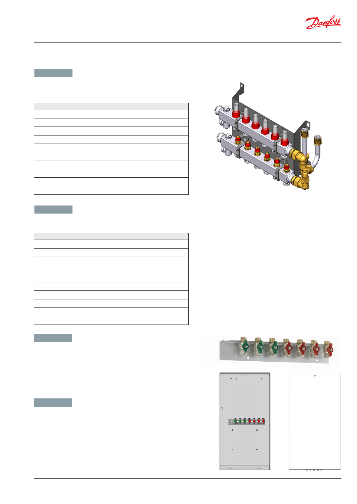
Verteilersystem für VX-F: Verteilersystem für Fussbodenheizung
ohne Beimischkreis, mit Durchflussmesser. Die Variante bieten 3 bis
12 Abgänge.
Typ Bestell-Nr.
Verteilerstation für VX-F, mit 3 Heizkreisen 145H0503
Verteilerstation für VX-F, mit 4 Heizkreisen 145H0504
Verteilerstation für VX-F, mit 5 Heizkreisen 145H0505
Verteilerstation für VX-F, mit 6 Heizkreisen 145H0506
Verteilerstation für VX-F, mit 7 Heizkreisen 145H0507
Verteilerstation für VX-F, mit 8 Heizkreisen 145H0508
Verteilerstation für VX-F, mit 9 Heizkreisen 145H0509
Verteilerstation für VX-F, mit 10 Heizkreisen 145H0510
Verteilerstation für VX-F, mit 11 Heizkreisen 145H0511
Verteilerstation für VX-F, mit 12 Heizkreisen 145H0512
ENGLISH - GB
Distribution unit for VX-F: Distribution system for floor heating without
shunt, with flow meter. This variant is available with 3 to 12 connections.
Type Code No.
Distribution unit for VX-F, with 3 heating circuits 145H0503
Distribution unit for VX-F, with 4 heating circuits 145H0504
Distribution unit for VX-F, with 5 heating circuits 145H0505
Distribution unit for VX-F, with 6 heating circuits 145H0506
Distribution unit for VX-F, with 7 heating circuits 145H0507
Distribution unit for VX-F, with 8 heating circuits 145H0508
Distribution unit for VX-F, with 9 heating circuits 145H0509
Distribution unit for VX-F, with 10 heating circuits 145H0510
Distribution unit for VX-F, with 11 heating circuits 145H0511
Distribution unit for VX-F, with 12 heating circuits 145H0512
GERMAN - DE
Montageschiene mit Kugelhähnen für einfache Montage auf der
Wand ist als Option erhältlich.
Einbauschränke einschl. Montageschiene mit Kugelhähnen für
Unterputzmontage und Tür für Einbauschränke sind als Option
erhältlich, sowie auch Montagefüße für Einbauschränke.
ENGLISH - GB
Mounting rail set with ball valves available as a pre-assembled
accessory set for mounting on the wall.
Recess boxes incl. mounting rail set with ball valves and door for
recess boxes are also available as an option, - as well as mounting
feet for recess boxes.
VI.LZ.O1.5B
© Danfoss | Produced by Danfoss Redan A/S | 2016.12 | 7
Page 8
Montageanleitung / Installation Guide Edelstahl Verteilersystem für VX-F/ Stainless steel distribution system for VX-F
5. HAUPTKOMPONENTE & ANSCHLUSS / MAIN COMPONENTS & CONNECTION
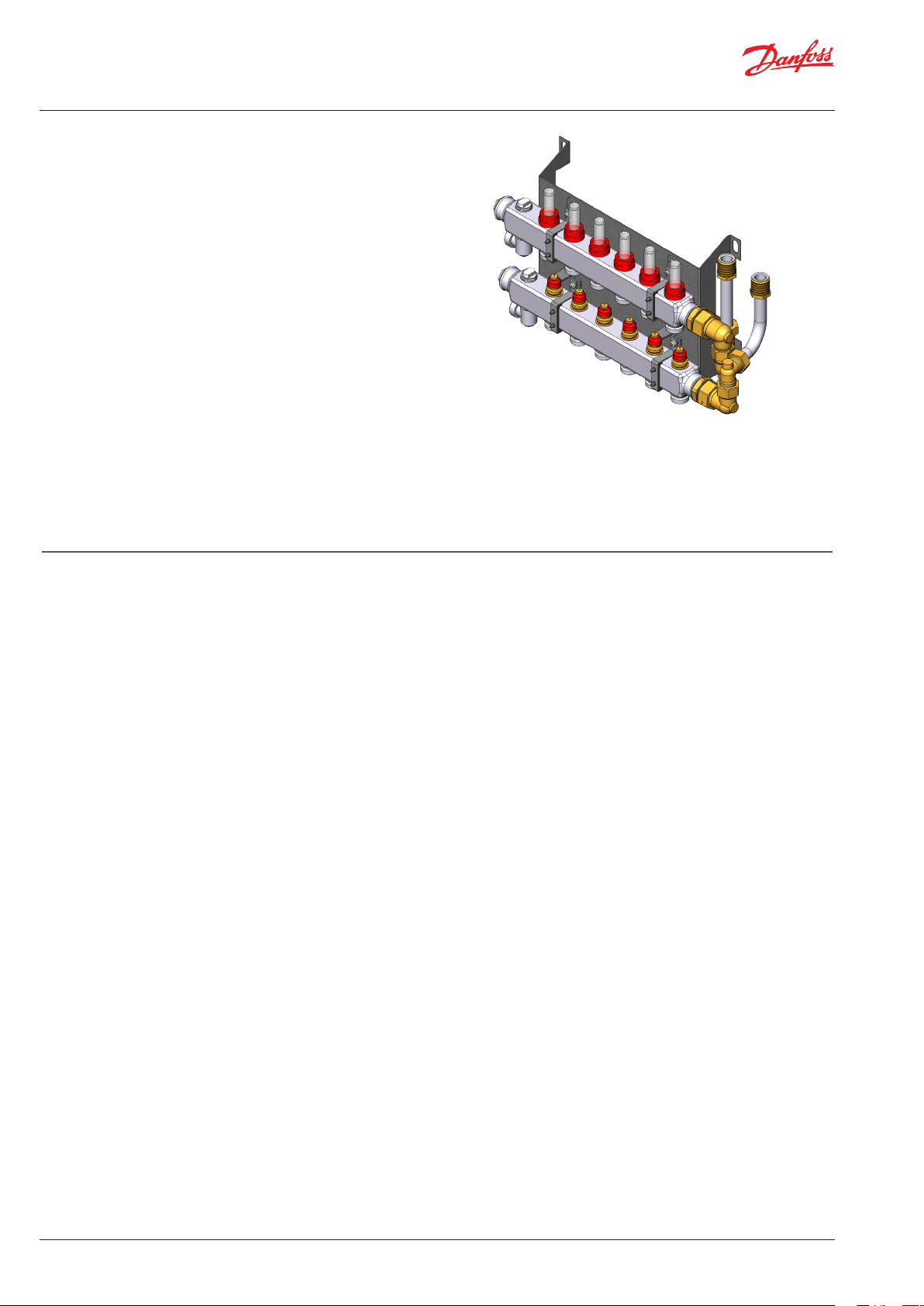
VER TEILERS YSTEM FÜR V XF
DISTRIBUTION SYSTEM FÜR VXF
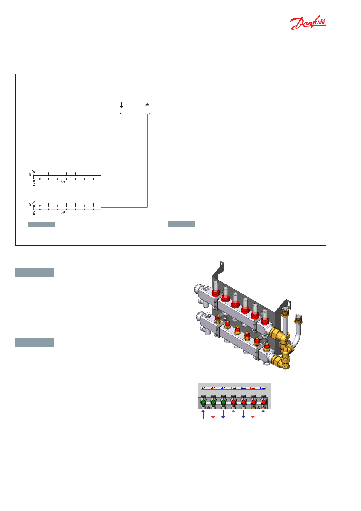
GERMAN - DE
19 Endstück mit manueller Entlüftung
58 Verteiler mit 7 Anschlüssen, mit Durchflussmesser
Fussboden
Vorlauf /
Floor heating
Supply
Fussboden
Rücklauf
Floor heating
Return
ENGLIS H - GB
19 Manual air vent and drain valve
58 Manifold w. 7 connecting pieces, with flow meter
GERMAN - DE
Abmessungen:
H 227 x B 478 - 810,5 x T 153 mm
Anschlussdimensionen: G ¾” (Innengewinde)
ENGLISH - GB
Dimensions:
H 227 x W 478 - 810,5 x D 153 mm
Connection sizes: G ¾” (internal thread)
KW / DCW
TWW / DHW
KW / DCW
8 | © Danfoss | Produced by Danfoss Redan A/S | 2016.12
FW Vorlauf / DH supply
FW Rücklauf / DH return
FBH Vorlauf / DH supply
FBH Rücklauf / FH return
VI.LZ.O1.5B
Page 9

Montageanleitung / Installation Guide Edelstahl Verteilersystem für VX-F/ Stainless steel distribution system for VX-F
5. HAUPTKOMPONENTE & ANSCHLUSS / MAIN COMPONENTS & CONNECTION
GERMAN - DE
19.
Endstück mit manueller Entlüftung
58.
Verteiler mit 7 Anschlüssen mit Durchflussmesser
19
ENGLISH
19.
Manual air vent and drain valve
58.
Manifold with 7 connecting pieces, with flow meter
19
58
58
GERMAN - DE
Optionen Bestell-Nr.
Unterputzkasten H 1350xB 690 x T 150 mm, einschl.
Montageschiene
Tür zu Unterputzkasten 145H4044, H 1350 x B 690 145H4104
Unterputzkasten H 1350 x B 850 x T 150 mm, einschl.
Montageschiene
Tür zu Unterputzkasten 145H4105, H 1350 x B 850 145H4106
Montagefüße für Unterputzkasten (2 Stück) 145H4232
Montageschiene einsch. Kugelhähne 145H4195
145H4044
145H4105
ENGLISH - GB
Options Code No.
Recess box H 1350x W 690 x D 150 mm, incl. mounting rail
Door for recess box 145H4044, H 1350 x W 690 145H4104
Recess box H 1350 x W 850 x D 150 mm, incl. mounting rail
Door for recess box 145H4105, H 1350 x W 850 mm 145H4106
Mounting feets for recess box (2 pcs) 145H4232
Monting rail incl. ball valves 145H4195
145H4044
145H4105
KW / DCW
TWW / DHW
KW / DCW
FW Vorlauf / DH supply
FW Rücklauf / DH return
FBH Vorlauf / DH supply
FBH Rücklauf / FH return
VI.LZ.O1.5B
© Danfoss | Produced by Danfoss Redan A/S | 2016.12 | 9
Page 10

Montageanleitung / Installation Guide Edelstahl Verteilersystem für VX-F/ Stainless steel distribution system for VX-F
6. MONTAGE / MOUNTING
GERMAN - DE
Die Verteiler passen auf der Rückplatte der Einbauschränke und
können auch auf der Wand montiert werden.
Sie sind für den separaten Einbau oder für die Montage zusammen
mit den bekannten Danfoss Wohnungsstationen Type VX-F
vorbereitet.
Einbauschränke für Unterputzausführung sind in zwei Größen
erhältlich.
3-6 Kreise passen in die:
145H4044: Einbauschrank einschl. Montageschiene
B 690 x H 1350 x T 150.
145H4104: Tür B 690 x H 1350
7-11 Kreise passen in die:
145H4105: Einbauschrank einschl. Montageschiene
B 850 x H 1350 x T 150.
145H4106: Tür B 850 x H 1350
ENGLISH - GB
The distributior units fits on the back plate of the recess boxes
and can also be mounted on the wall.
They can
VX-F flat station range.
Recess boxes for built-in variants are available in two sizes:
3-6 circuits fits the:
1145H4044: Recess box incl. mounting rail
W 690 x H 1350 x D 150.
be installed separately or be implemented with the Danfoss
A
B
VX-F mit Montageschiene mit TWWZirkulationssatz-Montage und Verteilerstation mit 6 Heizkreisen.
VX-F with mounting rail with DHW
circulation and distribution unit with 6
heating circuits
VX-F mit Montageschiene mit TWW-ZirkulationssatzMontage und Verteilerstation mit 12 Heizkreisen.
VX-F with mounting rail with DHW circulation and
distribution unit with 12 heating circuits.
145H4104: Door W 690 x H 135
7-11 circuits fit the:
145H4105: Recess box incl. mounting rail
W 850 x H 1350 x D 150.
145H4106: Door W 850 x H 1350
10 | © Danfoss | Produced by Danfoss Redan A/S | 2016.12
Unterputzmontage in Einbauschrank /
Recess mounting in recess box
VI.LZ.O1.5B
Page 11

Montageanleitung / Installation Guide Edelstahl Verteilersystem für VX-F/ Stainless steel distribution system for VX-F
7. MONTAGE IN EINBAUSCHRANK / MOUNTING IN RECESS BOX
GERMAN - DE
Montage
Schließen Sie das Verteilersystem gemäß der folgenden Instruktion
und/oder gemäß den Hinweisen in dieser Anleitung an die Hausinstallation an.
ENGLISH - GB
Mounting
Connect the distribution system to the household piping in accordance
with the labelling on the unit and/or in accordance with the instructions in this manual.
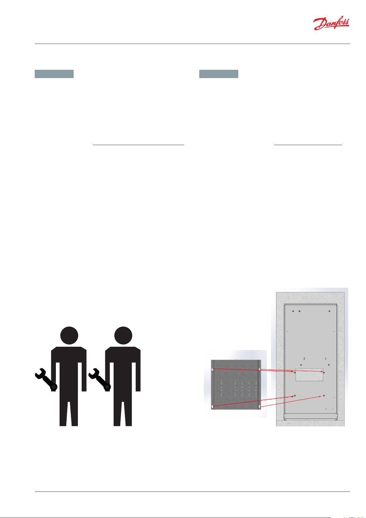
Schritt
Unterputzschrank wird mit mittig platzierter, drehbarer Montageschiene, wie oben gezeigt, geliefert.
1 2 3
Step
The recess box is supplied with a center-mounted, rotatable mounting
rail, as shown above.
Schritt
Die mittig platzierte Montageschiene demontieren und an die
unteren Schrauben montieren, wie Oben gezeigt.
Danach den Unterputzschrank einmauern oder in Leichtbauwand
einbauen.
Step
Detach the center-mounted mounting rail and mount it on the
lower screws, as shown.
Then install the under-wall cabinet or install it in a lightweight
wall.
VI.LZ.O1.5B
© Danfoss | Produced by Danfoss Redan A/S | 2016.12 | 11
Page 12

Montageanleitung / Installation Guide Edelstahl Verteilersystem für VX-F/ Stainless steel distribution system for VX-F
7. MONTAGE IN EINBAUSCHRANK / MOUNTING IN RECESS BOX
Schritt
Der Installateur schliesst die Hausverrohrung an die Montageschiene gemäß der Beschriftung auf der Montageschiene an:
KW Eintritt, TWW, KW Austritt, FW VOrlauf, FW Rücklauf (bis auf Fußbodenheizung)
und isoliert die Rohrleitungen.
Beachten Sie bitte immer bei der Einbau, daß genug Platz für
Rohranschluß ist.
Step
Installer connects the household pipes to the mounting rail
according to the label on the mounting rail
DCW inlet, DH W, DCW outl et, DH Supply DH return (excep t floor heating)
and insulates the pipes.
When installing, please ensure that there is enough space for
pipe connection.
Schritt
Wohnungsstation wird in Unterputzschrank montiert, mit den 7
montierten Kugelhähnen verschraubt und mit 2 Muttern M8 und
2 Unterlegschreiben M8x30 mm befestigt.
Step
Mount distribution unit in recess box, connect to the 7 ball valves
on the mounting rail, and fasten with 2 M8 nuts and 2 washers
M8x30 mm.
Schritt
Fussbodenverteilerstation wird mit 4 Muttern M8 an Rückwand
befestigt und die Fussbodenheizungsrohre mit den Kugelhähnen
der Montageschiene verschraubt.
Step
Mount distribution unit into position with 4 M8 nuts and connect
floor heating pipes to ball valves on mounting rail.
12 | © Danfoss | Produced by Danfoss Redan A/S | 2016.12
VI.LZ.O1.5B
Page 13

Montageanleitung / Installation Guide Edelstahl Verteilersystem für VX-F/ Stainless steel distribution system for VX-F
7. MONTAGE IN EINBAUSCHRANK / MOUNTING IN RECESS BOX
Schritt
Tür wird montiert.
Step
Mount door.
VI.LZ.O1.5B
© Danfoss | Produced by Danfoss Redan A/S | 2016.12 | 13
Page 14

Montageanleitung / Installation Guide Edelstahl Verteilersystem für VX-F/ Stainless steel distribution system for VX-F
8. EINSTELLUNG UND INBETRIEBNAHME / ADJUSTMENT AND COMMISSIONING
GERMAN - DE ENGLISH - GB
Verteiler mit Anschlüssen, mit Durchflussmesser
Durchflussmenge läss sich durch Drehen des Durchflussmessers
einstellen. Siehe bitte beigelegte Abbildungen.
Manifold with connecting pieces, with flow meter
Flow rate can be adjusted by turning the flowmeter. Please see enclosed pictures.
14 | © Danfoss | Produced by Danfoss Redan A/S | 2016.12
VI.LZ.O1.5B
Page 15

Montageanleitung / Installation Guide Edelstahl Verteilersystem für VX-F/ Stainless steel distribution system for VX-F
VI.LZ.O1.5B
von oben
© Danfoss | Produced by Danfoss Redan A/S | 2016.12 | 15
Page 16

Montageanleitung / Installation Guide Edelstahl Verteilersystem für VX-F/ Stainless steel distribution system for VX-F
088R0248| 15.12.2005 | Version 03
9. REGELTECHNIK - FUSSBODENHEIZUNG / CONTROL - FLOOR HEATING
GERMAN - DE ENGLISH - GB
Die Verteilersysteme für VX-F können mit fest verdrahtetem Heizkreisregler FH-WC 230 V und Thermo-Motoren TWA-A NC gemäß
Anzahl der Heizkreise versehen verden.
Dadurch wird Anschluss an einen elektronischen programmier-
baren Raumthermostat ermöglicht.
Zusammen mit dem Raumthermostat wird der TWA-A zum ON/OF
Regelung der Anlage verwendet.
Elektrische Verbindung zwischen Thermo-Motor Danfoss TWA-A
und Heizkreisregler FH-WC ist bauseits herzustellen.
Weitere Verkabelung ist am Ort herzustellen.
Elektrischer Anschluss
Der elektrische Anschluss des Verteilersystems darf nur von autorisiertem Personal durchgeführt werden.
Die Station muss an eine Netzversorgung mit 230 VAC angeschlossen werden.
Die Stromversorgung/der Anschluss muss gemäß den geltenden
Vorschriften und Anweisungen eingerichtet/vorgenommen werden.
Die Fernwärmestation muss an einen externen Schalter angeschlossen werden, sodass sie für Wartungs-, Reinigungs und Reparaturar
beiten oder bei Notfällen vom Netz getrennt werden kann.
Nicht vergessen, Potentialausgleich gemäß den geltenden lokalen
Vorschriften zu etablieren.
The distribution systems for VX-F stations can be provided with hardwired master controller FH-WC 230 V and thermo-actuators TWA-A
NC in accordance with the number of heating circuits.
Thereby connection to an electronic programmable room ther-
mostat is enabled.
Together with the room thermostat the TWA-A is used for ON / OF
control of the system.
Electrical wiring between thermo-actuator Danfoss TWA-A and
controller FH-WC is made on site.
Further wiring mus
Electrical connection
The electrical connection of the substation must be performed by
aqualified and authorised electrician in compliance with all applicable
rules and regulations.
The station should be connected to a 230 V AC power supply.
The power supply / connection must be carried out in accordance
with the applicable regulations and instructions.
The station must be wired and connected to an external main
-
switchso that it can be disconnected during maintenance, cleaning
and repairs or in the event of an emergency.
Do not forget to establish potential equalization in accordance
with the applicable regulations and instructions.
INSTRUCTIONS
TWA-A
For Danfoss RA valves
TWA-V
For Danfoss RAV/VMT valves
TWA-L
For Danfoss RAVL valves
TWA-K
For Heimeier/MNG/Oventrop
valves with M30 × 1.5 connection,
generally as per attached drawing.
Other valves must be veried
individually to ensure correct
valve closing measurement and
valve top geometry.
TWA-D
For Danfoss RTD valves
*) 24 V Class II transformer (SELV)
**) 230 V max. 3 A pre-fuse
VI.SB.H3.02 12-2005 Produced by Danfoss Industri Service 05.09 JJ-Bi.DS
TWA NC
Verteilersystem mit Heizkreisregler FH-WC und Thermo-Motoren TWA-A NC /
Distribution system with master controller FH-WC and thermo-actuators TWA-A NC
16 | © Danfoss | Produced by Danfoss Redan A/S | 2016.12
VI.LZ.O1.5B
Page 17

Montageanleitung / Installation Guide Edelstahl Verteilersystem für VX-F/ Stainless steel distribution system for VX-F
Schaltdiagramm / Wiring diagram
VI.LZ.O1.5B
© Danfoss | Produced by Danfoss Redan A/S | 2016.12 | 17
Page 18

Montageanleitung / Installation Guide Edelstahl Verteilersystem für VX-F/ Stainless steel distribution system for VX-F
10. Wartung / Maintenance
GERMAN - DE ENGLISH - GB
Wartungsarbeiten
Sind nur von qualifizierten und autorisierten Personen durchzuführen.
Überprüfung
Es unterliegt es der sorgfaltspflicht der Betrieber, in regelmäßigen
Abständen Inspektionen und wenn nötig Instandhaltungsarbeiten
laut dieser und anderen Anleitungen durchführen zu lassen. Im
Rahmen der o. g. Wartungsarbeiten sind alle Schmutzfänger zu
reinigen, alle Verschraubungen und Verbindungen nachzuspannen und die Sicherheitsventile durch Drehen des Handgriffes in
die markierte Richtung zu überprüfen.
Maßnahmen nach Wartungsarbeiten
Nach den Wartungsarbeiten und vor dem Einschalten der Anlage:
– Alle gelösten Schraubenverbindungen auf festen Sitz überprüfen.
– Überprüfen, ob alle zuvor entfernten Schutzvorrichtungen,
Abdeckungen wieder ordnungsgemäß eingebaut sind.
– Arbeitsbereich säubern und evtl. ausgetretene Stoffe entfernen.
– Alle verwendeten Werkzeuge, Materialien und sonstige
Ausrüstungen aus dem Arbeitsbereich wieder entfernen.
– Energieversorgung einschalten und von Leckagen überwachen.
– Anlage entlüften.
– Wenn nötig die Anlage neu einstellen.
– Sicherstellen, dass alle Sicherheitseinrichtungen des Gerätes
und der Anlage wieder einwandfrei funktionieren.
Maintenance work
Is only to be carried out by qualified and authorised personnel.
Inspection
The water heater should be checked regularly by authorised person-
nel. Any necessary maintenance must be performed in accordance
with the instructions in this manual and other sets of instructions.
During service the dirt strainers are to be cleaned – including the
filter on the controller, all pipe connections must be tightened and
the safety valve must be function tested by turning the lever.
Measures after maintenance work
After maintenance work and before commissioning:
– Check that all screwed connections are tight.
– Check that all safety features, covers, that were removed, have
been replaced properly.
– Clean the working area and remove any spilled materials.
– Clear all tools, materials and other equipment from the working
area.
– Connect to energy supply and check for leaks.
– Vent the system.
– Carry out any necessary adjustment again.
– Make sure that all safety features on the device and the system
work properly.
18 | © Danfoss | Produced by Danfoss Redan A/S | 2016.12
VI.LZ.O1.5B
Page 19

Montageanleitung / Installation Guide Edelstahl Verteilersystem für VX-F/ Stainless steel distribution system for VX-F
11. EU GUTACHTEN / EU DECLARATION OF CONFORMITY
VI.LZ.O1.5B
© Danfoss | Produced by Danfoss Redan A/S | 2016.12 | 19
Page 20

Montageanleitung / Installation Guide Edelstahl Verteilersystem für VX-F/ Stainless steel distribution system for VX-F
12. INBETRIEBNAHMEZERTIFIKAT
Die Station ist die direkte Verbindung zwischen der Fernwärmeversorgung und der Hausinstallation.
Vor der Inbetriebnahme der Wohnungsstation ist die übrige Anlage gründlich zu spülen und die Dichtheit der Verbindungen ist zu überprüfen. Sobald das System mit Wasser gefüllt worden ist, müssen alle Rohrverbindungen, bevor Druckprobe auf Dichtheit, nachgezogen
werden. Die Schmutzfänger reinigen und die Einstellungen gemäss der Hinweise dieser Betriebsanleitung durchführen.
Beim Einbau sind alle örtlichen Standards und Vorschriften einzuhalten.
Installation und erste Inbetriebnahme dürfen nur von qualifizierten und autorisierten Personen durchgeführt werden.
Die Station ist in der Fabrik auf Dichtigkeit vor der Auslieferung geprüft worden, aber nach Transport, Handhabung und Aufheizen der Anlage
sind sämtliche Verschraubungen und Anschlusse zu kontrollieren und gegebenenfalls nachzuziehen. Bitte beachten Sie, dass die Verbindungen mit EPDM Gummidichtungen ausgeführt werden können. Deshalb ist es sehr wichtig die Überwurfmutter nicht zu überspannen,
da dies zu Undichtigkeiten führen kann. Der Hersteller übernimmt keine Haftung für Leckagen, die aus Überspannung zurückzuführen sind.
Diese Anlage wurde nachgezogen, angepasst und in Betrieb genommen
den:
von Installateur:
Datum/Jahre
Firmenname (Stempel)
20 | © Danfoss | Produced by Danfoss Redan A/S | 2016.12
VI.LZ.O1.5B
Page 21

Montageanleitung / Installation Guide Edelstahl Verteilersystem für VX-F/ Stainless steel distribution system for VX-F
12. COMMISSIONING CERTIFICATE
The unit is the direct link between the district heating supply network and the household piping system. All supply pipes and the pipes in
the household piping system must be checked and rinsed before commissioning. Once the system has been filled with water, all pipe
connections
must be retightened before performing pressure test for leaks. The dirt strainers must be cleaned and the unit must be adjusted
in accordance with the instructions in this manual.
It is important to comply with all technical regulations and the applicable legislation in every respect.
Installation and commissioning must only be performed by trained, authorised personnel.
The unit is checked in the factory for leaks before delivery. Leaks are however possible due to vibrations caused by transport, hand-ling and
heating of the system and therefore it is important to check all connections and to retighten if necessarys before commissioning.
Please note that the connections may feature EPDM gaskets! Therefore it is important that you DO NOT OVER-TIGHTEN the connections.
Over-tightening may result in leaks. Leaks caused by ove-rtightening or failure to retighten connections are not covered by the warranty.
This unit has been retightened, adjusted and commissioned
on the:
by installer:
Date/Year
Company name (stamp)
VI.LZ.O1.5B
© Danfoss | Produced by Danfoss Redan A/S | 2016.12 | 21
Page 22

Montageanleitung / Installation Guide Edelstahl Verteilersystem für VX-F/ Stainless steel distribution system for VX-F
22 | © Danfoss | Produced by Danfoss Redan A/S | 2016.12
VI.LZ.O1.5B
Page 23

Montageanleitung / Installation Guide Edelstahl Verteilersystem für VX-F/ Stainless steel distribution system for VX-F
VI.LZ.O1.5B
© Danfoss | Produced by Danfoss Redan A/S | 2016.12 | 23
Page 24

Danfoss Redan A/S · District Heating · Omega 7, Søften · DK-8382 Hinnerup · Denmark
Tel.: +45 87 43 89 43 · Fax: +45 87 43 89 44 · redan@danfoss.com · www.redan.danfoss.dk
24 | © Danfoss | Produced by Danfoss Redan A/S | 2016.12
VI.LZ.O1.5B
 Loading...