

Page 1
Data Sheet
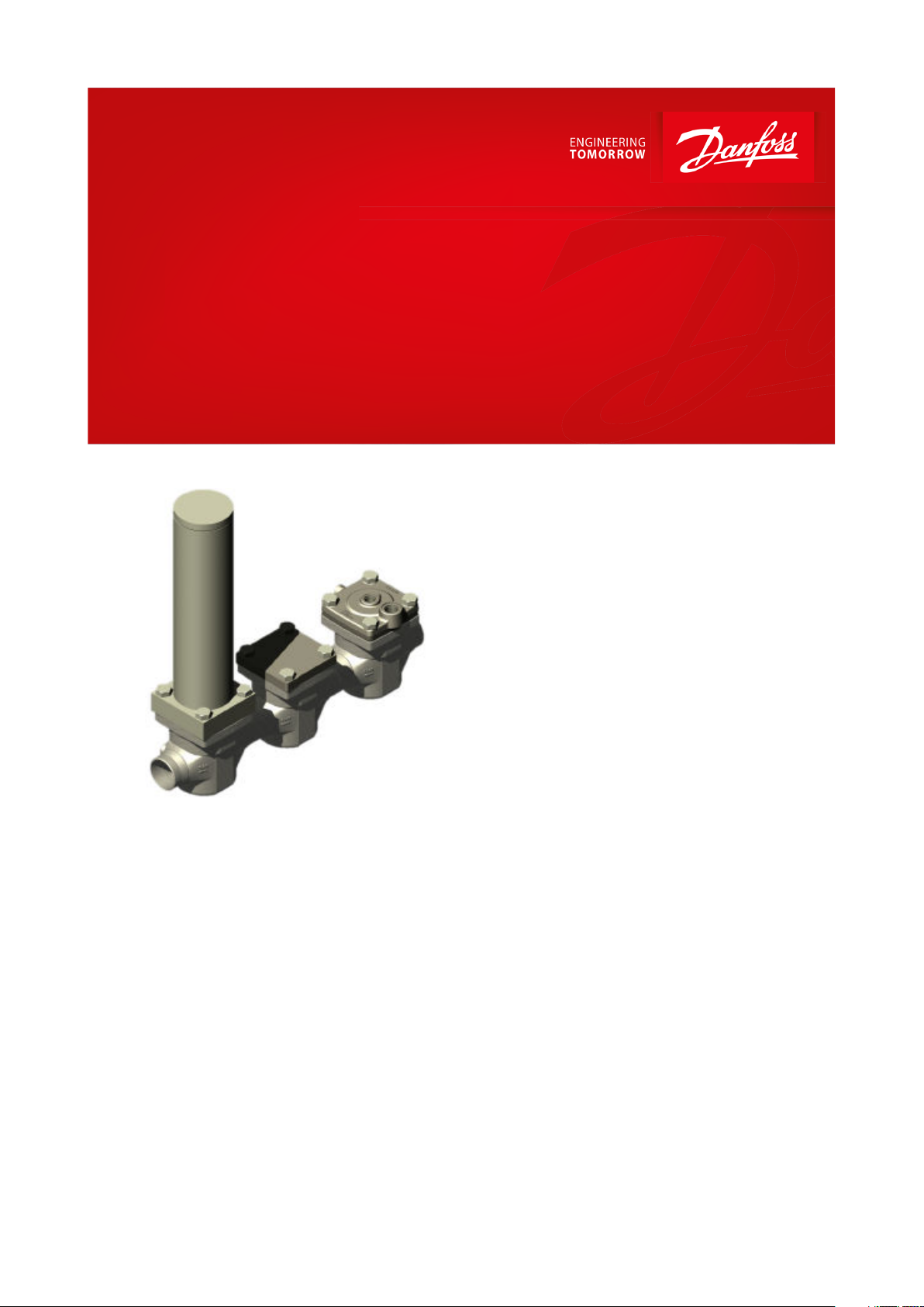
Eco-Damper
ICD damper, ICC Check valve
and ICS control valve
(3 valve) system build on the ICV modular concept
The Danfoss Eco-damper solution is a 3
component (3 valve) system build on the ICV
modular concept.
Each component consists of an ICV housing
and 1 of 3 modules performing the functions
Dampening (ICD), Non-return (ICC) and Control
(ICS 1 or 3 pilots) respectively.
The Danfoss Eco-damper solution is used in the
economizer line of typical screw compressors
to dampen the pulsations from the compressor.
The Eco damper system is designed for high
damping eciency over a broad band of low
frequencies with neglectable pressure drop.
It comes in sizes 32 and 50 and is oered from a
parts program giving a wide variety of
connection types and sizes.
The ICD is a unique damping system combining
the Helmholz, Quarter wave and Expansion
chamber principles into a broad band damper,
able to reduce the Ammonia pulsations by 30%
to 80% for critical frequencies in the frequency
range of 100 to 500 Hz.
AI310433586905en-000201
Page 2

Eco-Damper - ICD damper, ICC Check valve and ICS control valve
Features
• Designed for Industrial Refrigeration applications for a maximum working pressure of 52 bar / 754 psig.
• Applicable to R717 (Ammonia)
• Direct welded connections
• Connection types include butt weld, socket weld and solder connections
• Low temperature steel body
• Low weight and compact design
• The 3 top covers can be turned in any of 4 orientations without aecting the individual functions
• Manual opening of the solenoid valve (ie. the line) possible
• Robust PTFE seat secures long lasting solenoid valve function
• Service friendly design
© Danfoss | Climate Solutions | 2021.12 AI310433586905en-000201 | 2
Page 3
Description
ICD, ICC, ICS 32
ICD, ICC, ICS 50
Valve body/connection material
Steel
Steel
Connection standard
EN 10220
ANSI (B 36.10)
ANSI (B 16.11)
EN 1254-1
ANSI (B 16.22)
EN 10220
ANSI (B 36.10)
ANSI (B 16.11)
EN 1254-1
ANSI (B 16.22)
Connection type
Butt weld
Socket weld
Solder connection
Butt weld
Socket weld
Solder connection
Min. opening dierential pressure
ICS = 0,07 bar (1 psi)
ICC = 0,04 bar (0.6 psi)
ICS = 0,07 bar (1 psi)
ICC = 0,04 bar (0.6 psi)
Pressure dierential for fully opening of the ICS
and ICC valves
ICS = 0,2 bar (2.9 psi)
ICC = 0,08 bar (1.2 psi)
ICS = 0,2 bar (2.9 psi)
ICC = 0,08 bar (1.2 psi)
Kv (m3/h)
ICC = 16.6
ICD = 17.7
ICC = 40.4
ICD = 39.4
Cv (USgal/min)
ICC = 19.3
ICD = 20.6
ICC = 47
ICD = 45.9
Temperature range
ICD Temp. Range from -20 °C – 150 °C / - 4 °F – 302 °F
ICC Temp. Range from -60 °C – 120 °C / -76 °F – 248 °F
ICS Temp. Range from -60 °C– 120 °C / -76 °F – 248 °F
ICD Temp. Range from -20 °C – 150 °C / - 4 °F – 302 °F
ICC Temp. Range from -60 °C – 120 °C / -76 °F – 248 °F
ICS Temp. Range from -60 °C – 120 °C / -76 °F – 248 °F
Max. working pressure
52 bar / 754 psig
52 bar / 754 psig
Eco-Damper - ICD damper, ICC Check valve and ICS control valve
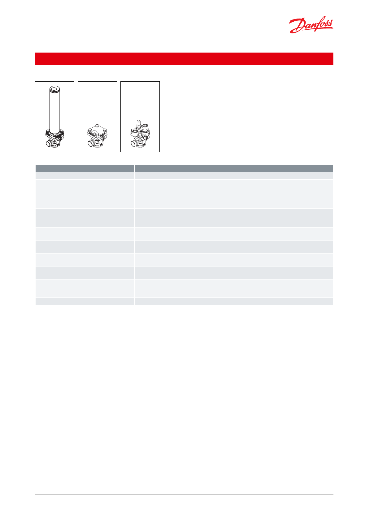
Portfolio overview
ICD, ICC, ICS 32 & 50
Table 1: Portfolio overview
© Danfoss | Climate Solutions | 2021.12 AI310433586905en-000201 | 3
Page 4
ICD
ICC
ICS
A
B B
Mass flow direction
Pulsation direction
Compressor
Fixation Rod
Pipe Clamp
Y
Z
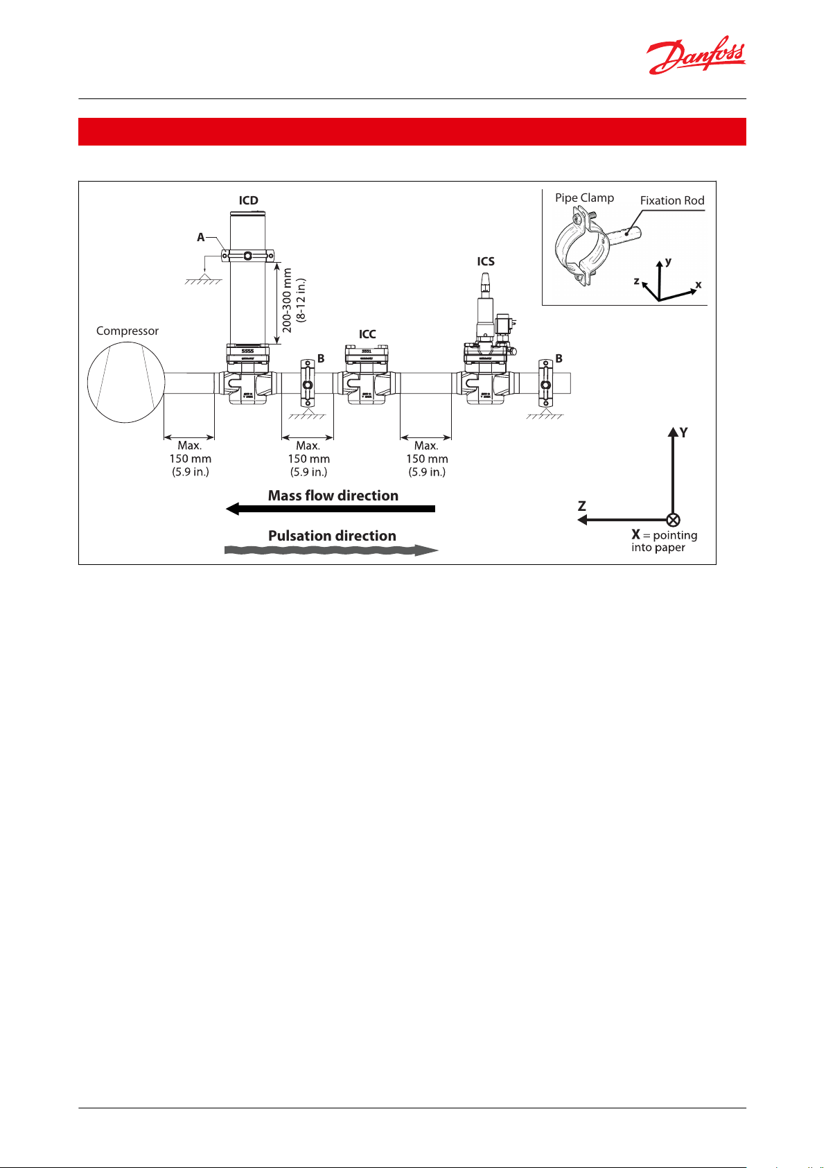
Eco-Damper - ICD damper, ICC Check valve and ICS control valve
Functions
Figure 1: Functional diagram
Though the refrigerant ow in the economizer line is towards the compressor, the pulsations moves in the opposite
direction. Due to this phenomenon the sequence of the 3 components is important. Seen from the compressor the
dampening comes rst followed by ow alignment and ow control.
It is equally important to orientate the valve housings with the arrow pointing in the mass ow direction (pointing
towards the compressor).
Distances between the single components are of great importance and recommendations must be followed.
The Eco damper is designed for high eciency dampening of pulsation pressure peeks and creating unidirectional
ow in economizer lines of Ammonia systems.
Depending on the RPM’s and geometry of the typical screw compressor the frequency and amplitude of the
pulsations in the economizer lines will vary.
The ICD damper is specically designed for dampening of the critical Ammonia pulsations in the broad band of 100
to 500 Hz.
A simple calculation will clarify if a certain compressor set-up will result in pulsation frequencies between 100 and
500 Hz and this clarication should be made before considering the Eco damper solution. Please look into the
Selection section.
The ICD is a unique damping system combining the Helmholz, Quarter wave and Expansion chamber principles into
a broad band damper, able to reduce the Ammonia pulsations by 30% to 80% for critical frequencies in the specied
frequency band.
The ICC non-return/check valve is a robust valve optimized to withstand pulsations in the same low frequency band.
The ICC features the ability to reduce small pulsating movements in the wrong direction with an overall low
pressure drop for the main ow direction.
The ICS control valve is the ordinary valve used for allround control purposes. In the Eco-Damper application the 3
pilot version is oered to be able to include more functions like solenoid and/ or pressure control. The solenoid
function is the on/o function for the entire Eco-Damper.
© Danfoss | Climate Solutions | 2021.12 AI310433586905en-000201 | 4
Page 5
In N/mmAB
X
275.000
375.000
Y
14.000
36.000Z14.000
36.000
In N/mmAB
X
275.000
36.000Y14.000
375.000
Z
14.000
36.000
Equalizer por t
Female Male
Housing size
ICD connection size
ICC connection size
32
DN32
DN32
DN40
DN4050DN50
DN50
DN65
DN65
Eco-Damper - ICD damper, ICC Check valve and ICS control valve
The Eco-Damper solution must be assembled like shown in the above gure with the ICD next to the compressor
followed by the ICC and nally the ICS.
NOTE:
In order to prevent exceeding vibrations caused by the ICD eigenfrequency, pipe clamps for fastening the
ICD must be installed, and the max distances have to be followed (Figure 1: Functional diagram. Pos. A and B
are mandatory). The pipe clamp for pos. A is included in the box. The B pipe clamps and the support must be
strong and robust xation points to help reduce vibrations.
As a guideline the values for stiness of the clamp support can be found in following tables. For reference of
coordinate system see Figure 1: Functional diagram. The pipe clamps at A and B have to provide the
following minimum stiness if the xation rod is pointing in x-direction:
The pipe clamps at B have to provide the following minimum stiness if the xation rod is pointing in ydirection (clamp at A remains unchanged):
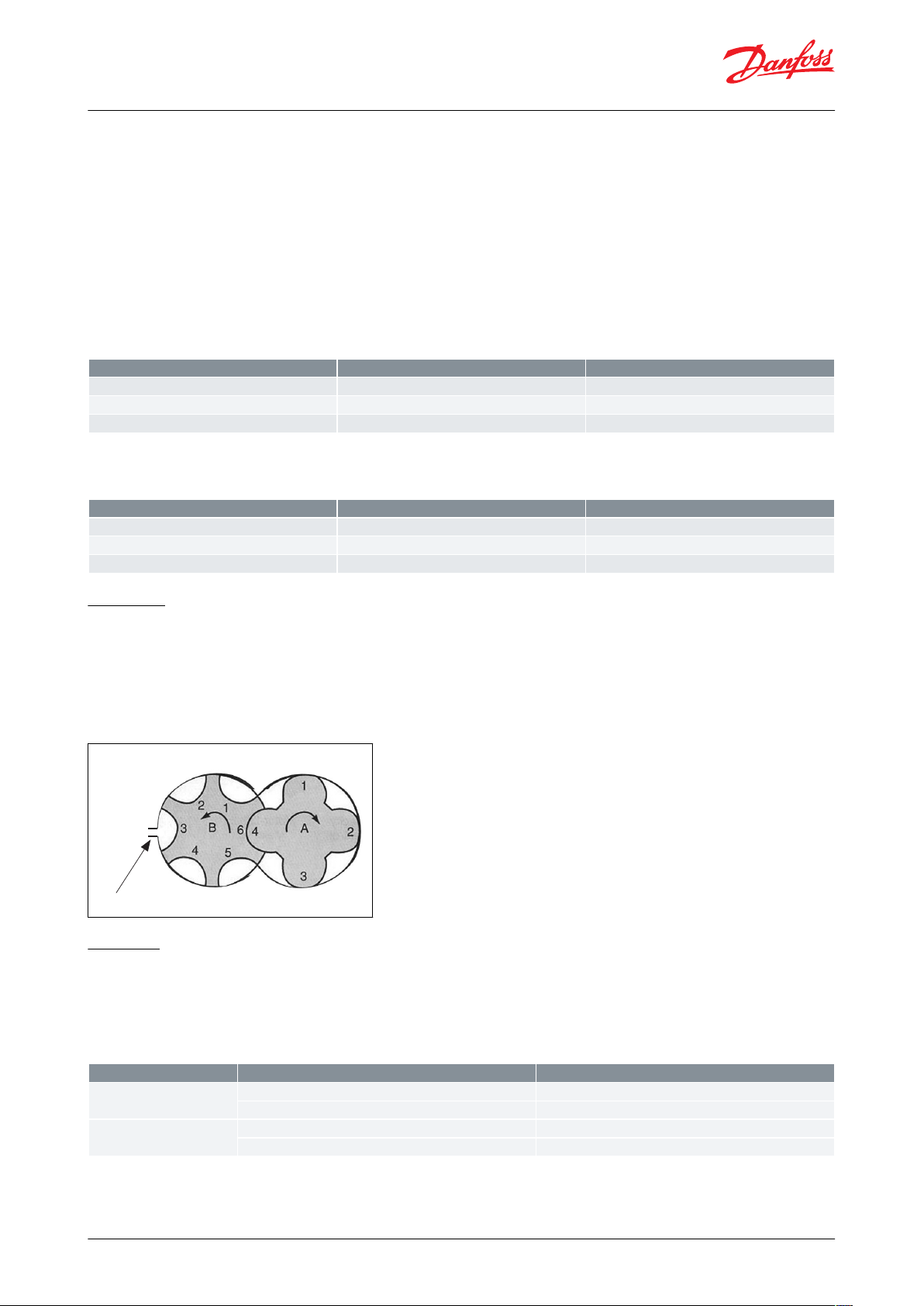
Selection
To determine the actual pulsation frequency of a compressor use this formula:
Frequency = RPM (female) * number of grooves (female) / 60 [Hz]
Example: Frequency = 2000 * 6 / 60 = 200 Hz
If 100 Hz < Frequency < 500 Hz dampening is possible with the Eco damper.
Further selection should be based on housing size, connection size and capacity.
Capacity
Once the frequency range is conrmed to be within damper range, the next step is to nd the right valve capacity.
For selection and capacity calculation please refer to Coolselector®2
For application and compressor model conrmation please contact Danfoss.
These criteria should be used for selection.
© Danfoss | Climate Solutions | 2021.12 AI310433586905en-000201 | 5
Page 6

Eco-Damper - ICD damper, ICC Check valve and ICS control valve
• Complete Eco-Damper solution (ICD+ICC): Lowest pressure drop @ min. and max. capacity
• Check ICC: Pressure drop min. @ minimum capacity (to be outside un-stable area) Check pressure drop max. @
maximum capacity
• Control/solenoid valve: Pressure drop @ min. and max. capacity
• Check control/solenoid valve: Pressure drop min. @ minimum capacity (to be outside un-stable area) Check
pressure drop max. @ maximum capacity
NOTE:
For assistance in relation to selection of right valve capacity please contact Danfoss.
© Danfoss | Climate Solutions | 2021.12 AI310433586905en-000201 | 6
Page 7

Eco-Damper - ICD damper, ICC Check valve and ICS control valve
Media
Refrigerants
Applicable to R717 (Ammonia)
New refrigerants
Danfoss products are continually evaluated for use with new refrigerants depending on market requirements.
When a refrigerant is approved for use by Danfoss, it is added to the relevant portfolio, and the R number of the
refrigerant (e.g. R513A) will be added to the technical data of the code number. Therefore, products for specic
refrigerants are best checked at store.danfoss.com/en/, or by contacting your local Danfoss representative.
© Danfoss | Climate Solutions | 2021.12 AI310433586905en-000201 | 7
Page 8

Max. temperature range
Media: -60 °C – 120 °C / -76 °F – 248 °F.
Max. working pressure
52 bar / 754 psig
Min. opening dierential pressure
ICS = 0,07 bar (1 psi)
ICC = 0,04 bar (0.6 psi)
Pressure dierential for fully opening of the ICS and ICC valves
ICS = 0,2 bar (2.9 psi)
ICC = 0,08 bar (1.2 psi)
Kv (m3/h)
Size 32: 17
Size 50: 44
Cv (USgal/min)
Size 32: 20
Size 50: 51
Coil requirement for ICS+EVM
Coils to be IP67
Damping frequency range
100 – 500Hz
Surface protection
For excellent corrosion protection all valve outer surfaces are zinc-chromated.
The Damper module is painted.
1
3
2
4
5
1
3
2b
2a
2
4
6c
C
6
7
11
12
2
4
8
9
10
6c
C
6a
6b
D
E
A
B
1
No
Part
Material
EN
ASTM
JIS
1
Body
Low temperature steel
G20Mn5QT
EN 10213-3
LCC A352
SCPL1 G5151
2
Top assembly
Low temperature steel
G20Mn5QT,
EN 10213-3
P285QH+QT 10222-4
LCC A352
LF2, A350
SCPL1 G5151
2a
O-ring
Cloroprene (Neoprene)
2b
O-ring
Cloroprene (Neoprene)
3
Gasket
Fiber, non-asbestos
4
Bolts
Stainless steel
A2-70, EN 1515-1
Grade B8 A320
A2-70, B 1054
Eco-Damper - ICD damper, ICC Check valve and ICS control valve
Product specication
Pressure and temperature
Table 2: Pressure and temperature
Material specication
Table 3: Material specication
© Danfoss | Climate Solutions | 2021.12 AI310433586905en-000201 | 8
Page 9

No
Part
Material
EN
ASTM
JIS
5
Pipe support
Stainless Steel
6
Function module (assembled)6ao-ring
Cloroprene (Neoprene)
6b
o-ring
Cloroprene (Neoprene)
6c
Washer plate
SteelACylinder
SteelBPiston
SteelCValve plate
PTFEDSpring
SteelECone
Steel7Gasket
Fiber, non-asbestos
8
Plug
Steel9Gasket
Aluminium
10
Manual operating spindle
Steel11Plug
Steel12Gasket
Aluminium
ICV 32
ICV 50
DASOCSDSA
L
ID
Butt-weld DIN
Butt-weld ANSI
Socket weld ANSI
Solder DIN
Solder ANSI
Eco-Damper - ICD damper, ICC Check valve and ICS control valve
Connections
The Eco-Damper concept
The Eco-Damper concept is developed to highest exibility of direct welded connections. For valve sizes ICV 32 and
50 a wide range of connection sizes and types is available.
The direct welded (non-anged) connections secures low risk of leakage.
Table 4: There are two valve bodies available
There is a wide range of connection types available:
• D: Butt weld, EN 10220
• A: Butt weld, ANSI (B 36.10)
• SOC: Socket weld, ANSI (B 16.11)
• SD: Solder connection, EN 1254-1
• SA: Solder connection, ANSI (B 16.22)
Table 5: Design (valve)
© Danfoss | Climate Solutions | 2021.12 AI310433586905en-000201 | 9
Page 10

H₁ H₂
L
Connection
H1H
2
L
Weight
32 D (1 1/4 in.)
mm
40
482.57
145
7 Kg
in.
1.57
18.99
5.71
15.4 lbs
40 D (1 1/2 in.)
mm
40
482.57
145
6.8 Kg
in.
1.57
18.99
5.71
14.9 lbs
32 A (1 1/4 in.)
mm
40
482.57
145
6.8Kg
in.
1.57
18.99
5.71
15 lbs
40 A (1 1/2 in.)
mm
40
482.57
145
6.8 Kg
in.
1.57
18.99
5.71
15.1 lbs
32 SOC (1 1/4 in.)
mm
40
482.57
148
6.9 Kg
in.
1.57
18.99
5.83
15.3 lbs
35 SD (1 3/8 in. SA)
mm
40
482.57
148
6.8 Kg
in.
1.57
18.99
5.83
14.9 lbs
42 SD (1 5/8 in.)
mm
40
482.57
148
6.8 Kg
in.
1.57
18.99
5.83
14.9 lbs
42 SA (1 5/8 in.)
mm
40
482.57
148
6.8 Kg
in.
1.57
18.99
5.83
14.9 lbs
50 D (2 in.)
mm
59
503.74
200
12.2 Kg
in.
2.32
19.83
7.87
26.9 lbs
65 D (2 1/2 in.)
mm
59
503.74
210
12.6 Kg
in.
2.32
19.83
8.27
27.8 lbs
50 A (2 in.)
mm
59
503.74
200
12.3 Kg
in.
2.32
19.83
7.87
27.1 lbs
65 A (2 1/2 in.)
mm
59
503.74
210
12.6 Kg
in.
2.32
19.83
8.27
27.8 lbs
50 SOC (2 in.)
mm
59
503.74
216
13.4 Kg
in.
2.32
19.83
8.5
29.6 lbs
54 SD (2 1/8 in. SA)
mm
59
503.74
216
12.4 Kg
in.
2.32
19.83
8.5
27.2 lbs
Eco-Damper - ICD damper, ICC Check valve and ICS control valve
Dimensions and weights
ICD 32 and 50
Table 6: Housing with module
NOTE:
D = Butt-weld DIN ; A = Butt-weld ANSI ; J = Butt-weld JIS ; SOC = Socket weld ANSI ; SD = Solder DIN ; SA =
Solder ANSI ; FPT = Female Pipe Thread
© Danfoss | Climate Solutions | 2021.12 AI310433586905en-000201 | 10
Page 11

H₁ H₂
L
Connection
H1H
2
L
Weight
32 D (1 1/4 in.)
mm
40
86.8
145
6.5 Kg
in.
1.57
3.42
5.71
14.4 lbs
40 D (1 1/2 in.)
mm
40
86.8
145
6.6 Kg
in.
1.57
3.42
5.71
14.6 lbs
32 A (1 1/4 in.)
mm
40
86.8
145
6.6 Kg
in.
1.57
3.42
5.71
14.6 lbs
40 A (1 1/2 in.)
mm
40
86.8
145
6.7 Kg
in.
1.57
3.42
5.71
14.7 lbs
32 SOC (1 1/4 in.)
mm
40
86.8
148
6.8 Kg
in.
1.57
3.42
5.83
14.9 lbs
35 SD (1 3/8 in. SA)
mm
40
86.8
148
6.6 Kg
in.
1.57
3.42
5.83
14.6 lbs
42 SD (1 5/8 in.)
mm
40
86.8
148
6.6 Kg
in.
1.57
3.42
5.83
14.6 lbs
42 SA (15/8 in.)
mm
40
86.8
148
6.6Kg
in.
1.57
3.42
5.83
14.6 lbs
50 D (2 in.)
mm
59
111.25
200
9.1 Kg
in.
2.32
4.38
7.87
20 lbs
65 D (2 1/2 in.)
mm
59
111.25
210
9.5 Kg
in.
2.32
4.38
8.27
20.9 lbs
50 A (2 in.)
mm
59
111.25
200
9.1 Kg
in.
2.32
4.38
7.87
20.2 lbs
65 A (2 1/2 in.)
mm
59
111.25
210
9.5 Kg
in.
2.32
4.38
8.27
20.9 lbs
50 SOC (2 in.)
mm
59
111.25
216
10.3 Kg
in.
2.32
4.38
8.5
22.7 lbs
54 SD (2 1/8 in. SA)
mm
59
111.25
216
9.2 Kg
in.
2.32
4.38
8.5
20.3 lbs
Eco-Damper - ICD damper, ICC Check valve and ICS control valve
ICC 32 and 50
Table 7: Housing with top cover
NOTE:
D = Butt-weld DIN ; A = Butt-weld ANSI ; J = Butt-weld JIS ; SOC = Socket weld ANSI ; SD = Solder DIN ; SA =
Solder ANSI ; FPT = Female Pipe Thread
© Danfoss | Climate Solutions | 2021.12 AI310433586905en-000201 | 11
Page 12

H₁
H₂
H₄
L₁
H₃
L
Connection
H1H2H3H
4
L
L1L2B1B
2
Weight
ICS 1 Pi‐
lot
Weight
ICS 3 Pi‐
lots
32 D (1 1/4 in.)
mm
40
160
1007414551155187
4.5 kg
5 kg
in.
1.57
6.3
3.93
2.91
5.7120.5923.43
9.9 lb.
11 lb.
40 D (1 1/2 in.)
mm
40
160
1007414551155187
4.5 kg
5 kg
in.
1.57
6.3
3.93
2.91
5.7120.5923.43
9.9 lb.
11 lb.
32 A (1 1/4 in.)
mm
40
160
1007414551155187
4.5 kg
5 kg
in.
1.57
6.3
3.93
2.91
5.7120.5923.43
9.9 lb.
11 lb.
40 A (1 1/2 in.)
mm
40
160
1007414551155187
4.5 kg
5 kg
in.
1.57
6.3
3.93
2.91
5.7120.5923.43
9.9 lb.
11 lb.
32 SOC (1 1/4 in.)
mm
40
160
1007414851155187
4.5 kg
5 kg
in.
1.57
6.3
3.93
2.91
5.8320.5923.43
9.9 lb.
11 lb.
35 SD (1 3/8 in. SA)
mm
40
160
1007414851155187
4.5 kg
5 kg
in.
1.57
6.3
3.93
2.91
5.8320.5923.43
9.9 lb.
11 lb.
42 SD (1 5/8 in.)
mm
40
160
1007414851155187
4.5 kg
5 kg
in.
1.57
6.3
3.93
2.91
5.8320.5923.43
9.9 lb.
11 lb.
42 SA (1 5/8 in.)
mm
40
160
1007414851155187
4.5 kg
5 kg
in.
1.57
6.3
3.93
2.91
5.8320.5923.43
9.9 lb.
11 lb.
50 D (2 in.)
mm
59
181
1209320051156391
8.9 kg
9.2 kg
in.
2.32
7.13
4.72
3.66
7.8720.59
2.48
3.58
19.6 lb.
20.2 lb.
65 D (2 1/2 in.)
mm
59
181
1209321051156391
8.9 kg
9.2 kg
in.
2.32
7.13
4.72
3.66
8.2720.59
2.48
3.58
19.6 lb.
20.2 lb.
50 A (2 in.)
mm
59
181
1209320051156391
8.9 kg
9.2 kg
in.
2.32
7.13
4.72
3.66
7.8720.59
2.48
3.58
19.6 lb.
20.2 lb.
65 A (2 1/2 in.)
mm
59
181
1209321051156391
8.9 kg
9.2 kg
in.
2.32
7.13
4.72
3.66
8.2720.59
2.48
3.58
19.6 lb.
20.2 lb.
50 SOC (2 in.)
mm
59
181
1209321651156391
8.9 kg
9.2 kg
in.
2.32
7.13
4.72
3.66
8.520.59
2.48
3.58
19.6 lb.
20.2 lb.
54 SD (2 1/8 in. SA)
mm
59
181
1209321651156391
8.9 kg
9.2 kg
in.
2.32
7.13
4.72
3.66
8.520.59
2.48
3.58
19.6 lb.
20.2 lb.
Eco-Damper - ICD damper, ICC Check valve and ICS control valve
ICS 32 and 50
Table 8: Housing with module
NOTE:
D = Butt-weld DIN ; A = Butt-weld ANSI ; J = Butt-weld JIS ; SOC = Socket weld ANSI ; SD = Solder DIN ; SA =
Solder ANSI ; FPT = Female Pipe Thread
© Danfoss | Climate Solutions | 2021.12 AI310433586905en-000201 | 12
Page 13

ICS 3
3 x Valve body
32 D (1 1/4 in.)
027H3120
Table 10
1 x Function module set
ICD & ICC
027H3201
Table 11
1 x Function module ICS 32
027H3200
Table 12
1 x Top cover
3 pilots
027H3173
Table 13
32 D (1
1
⁄4 in.)
40 D (1
1
⁄2 in.)
42 SA (1
5
⁄8 in.)
42 SD (1
5
⁄8 in.)
027H3120
027H3125
027H3127
027H3128
35 SD (1
3
⁄8 in. SA)
32 A (1
1
⁄4 in.)
32 SOC (1
1
⁄4 in.)
40 A (1
1
⁄2 in.)
027H3123
027H3121
027H3122
027H3126
Description
Code Number
ICD & ICC 32
027H3201
Eco-Damper - ICD damper, ICC Check valve and ICS control valve
Ordering
ICD, ICC, ICS 32
Ordering from the parts programme
Table 9: Example (select from table 10 to 13)
Figure 2: ICV 32 valve body
Table 10: ICV 32 valve body w/dierent connections
NOTE:
D = Butt-weld DIN ; A = Butt-weld ANSI ; J = Butt-weld JIS ; SOC = Socket weld ANSI ; SD = Solder DIN ; SA =
Solder ANSI ; FPT = Female Pipe Thread
Figure 3: ICD & ICC
Table 11: ICD & ICC function module set
NOTE:
Including bolts, gaskets and o-rings
© Danfoss | Climate Solutions | 2021.12 AI310433586905en-000201 | 13
Page 14

ICS 1
ICS 3
Description
Code Number
ICS 32
027H3200
Description
Code Number
Top cover 1 Pilot
027H3172
(1)
Top cover 3 Pilots
027H3173
(2)
ICS 3
3 x Valve body
50 D (2 in.)
027H5120
Table 15
1 x Function module set
ICD & ICC
027H5201
Table 16
1 x Function module ICS 50
027H5200
Table 17
1 x Top cover
3 pilots
027H5173
Table 18
Eco-Damper - ICD damper, ICC Check valve and ICS control valve
Figure 4: ICS 32
Table 12: ICS 32 function module
NOTE:
Including gasket and O-rings
Figure 5: Top cover 1 Pilot
Figure 6: Top cover 3 Pilots
Table 13: ICS 32 top cover
(1)
(1)
Including bolts
Including bolts
(2)
(2)
Including bolts and one blanking plug
Including bolts and one blanking plug
ICD, ICC, ICS 50
Ordering from the parts programme
Table 14: Example (select from table 15 to 18)
Figure 7: ICV 50 valve body
© Danfoss | Climate Solutions | 2021.12 AI310433586905en-000201 | 14
Page 15

ICS 1
ICS 3
50 D (2 in.)
65 D (2
1
⁄2 in.)
54 SD (2
1
⁄8 in. SA)
50 A (2 in.)
027H5120
027H5124
027H5123
027H5121
50 SOC (2 in.)
65 A (2
1
⁄2 in.)
027H5122
027H5125
Description
Code Number
ICD & ICC 50
027H5201
Description
Code Number
ICS 50
027H5200
Description
Code Number
Top cover 1 Pilot
027H3172
(1)
Top cover 3 Pilots
027H3173
(2)
Eco-Damper - ICD damper, ICC Check valve and ICS control valve
Table 15: ICV 50 valve body w/dierent connections
NOTE:
D = Butt-weld DIN ; A = Butt-weld ANSI ; J = Butt-weld JIS ; SOC = Socket weld ANSI ; SD = Solder DIN ; SA =
Solder ANSI ; FPT = Female Pipe Thread
Figure 8: ICD & ICC
Table 16: ICD & ICC function module set
NOTE:
Including bolts, gaskets and o-rings
Figure 9: ICS 50
Table 17: ICS 50 function module
NOTE:
Including gasket and O-rings
Figure 10: Top cover 1 Pilot
Figure 11: Top cover 3 Pilots
Table 18: ICS 50 top cover
(1)
(1)
Including bolts
Including bolts
(2)
(2)
Including bolts and one blanking plug
Including bolts and one blanking plug
© Danfoss | Climate Solutions | 2021.12 AI310433586905en-000201 | 15
Page 16

Description
Code Number
ICC 32 function module
027H3202
ICC 50 function module
027H5202
Description
Code Number
ICC 32 repair kit
027H3039
ICC 50 repair kit
027H5017
Eco-Damper - ICD damper, ICC Check valve and ICS control valve
Spare parts and accessories
Figure 12: Function module
Table 19: Function module
Figure 13: Repair kit
Table 20: Repair kit
NOTE:
Including bolts, gaskets and o-rings
© Danfoss | Climate Solutions | 2021.12 AI310433586905en-000201 | 16
Page 17

ICD, ICC and ICS valves
Nominal bore
DN 32 - 50 (1 1/4 - 2 in.)
Classied for
Fluid group I
Category
II
Eco-Damper - ICD damper, ICC Check valve and ICS control valve
Certicates, declarations, and approvals
The list contains all certicates, declarations, and approvals for this product type. Individual code number may have
some or all of these approvals, and certain local approvals may not appear on the list.
Some approvals may change over time. You can check the most current status at danfoss.com or contact your local
Danfoss representative if you have any questions.
The ICV valve concept is designed to full global refrigeration requirements.
The individual components are CE, CRN and UL approved. For specic approval information, please contact Danfoss.
Table 21: Compliance
© Danfoss | Climate Solutions | 2021.12 AI310433586905en-000201 | 17
Page 18

Online support
Danfoss oers a wide range of support along with our products, including digital product information, software,
mobile apps, and expert guidance. See the possibilities below.
The Danfoss Product Store
The Danfoss Product Store is your one-stop shop for everything product related—no matter where
you are in the world or what area of the cooling industry you work in. Get quick access to essential
information like product specs, code numbers, technical documentation, certications, accessories,
and more.
Start browsing at store.danfoss.com.
Find technical documentation
Find the technical documentation you need to get your project up and running. Get direct access to
our ocial collection of data sheets, certicates and declarations, manuals and guides, 3D models
and drawings, case stories, brochures, and much more.
Start searching now at www.danfoss.com/en/service-and-support/documentation.
Danfoss Learning
Danfoss Learning is a free online learning platform. It features courses and materials specically
designed to help engineers, installers, service technicians, and wholesalers better understand the
products, applications, industry topics, and trends that will help you do your job better.
Create your Danfoss Learning account for free at www.danfoss.com/en/service-and-support/learning.
Get local information and support
Local Danfoss websites are the main sources for help and information about our company and
products. Find product availability, get the latest regional news, or connect with a nearby expert—all
in your own language.
Find your local Danfoss website here: www.danfoss.com/en/choose-region.
Spare Parts
Get access to the Danfoss spare parts and service kit catalog right from your smartphone. The app
contains a wide range of components for air conditioning and refrigeration applications, such as
valves, strainers, pressure switches, and sensors.
Download the Spare Parts app for free at www.danfoss.com/en/service-and-support/downloads.
Coolselector®2 - nd the best components for you HVAC/R system
Coolselector®2 makes it easy for engineers, consultants, and designers to nd and order the best
components for refrigeration and air conditioning systems. Run calculations based on your operating
conditions and then choose the best setup for your system design.
Download Coolselector®2 for free at coolselector.danfoss.com.
Any information, including, but not limited to information on selection of product, its application or use, product design, weight, dimensions, capacity or any other
technical data in product manuals, catalogues descriptions, advertisements, etc. and whether made available in writing, orally, electronically, online or via download,
shall be considered informative, and is only binding if and to the extent, explicit reference is made in a quotation or order conrmation. Danfoss cannot accept any
responsibility for possible errors in catalogues, brochures, videos and other material. Danfoss reserves the right to alter its products without notice. This also applies to
products ordered but not delivered provided that such alterations can be made without changes to form, t or function of the product. All trademarks in this material
are property of Danfoss A/S or Danfoss group companies. Danfoss and the Danfoss logo are trademarks of Danfoss A/S. All rights reserved.
© Danfoss | Climate Solutions | 2021.12 AI310433586905en-000201 | 18
 Loading...