

Page 1
User Manual
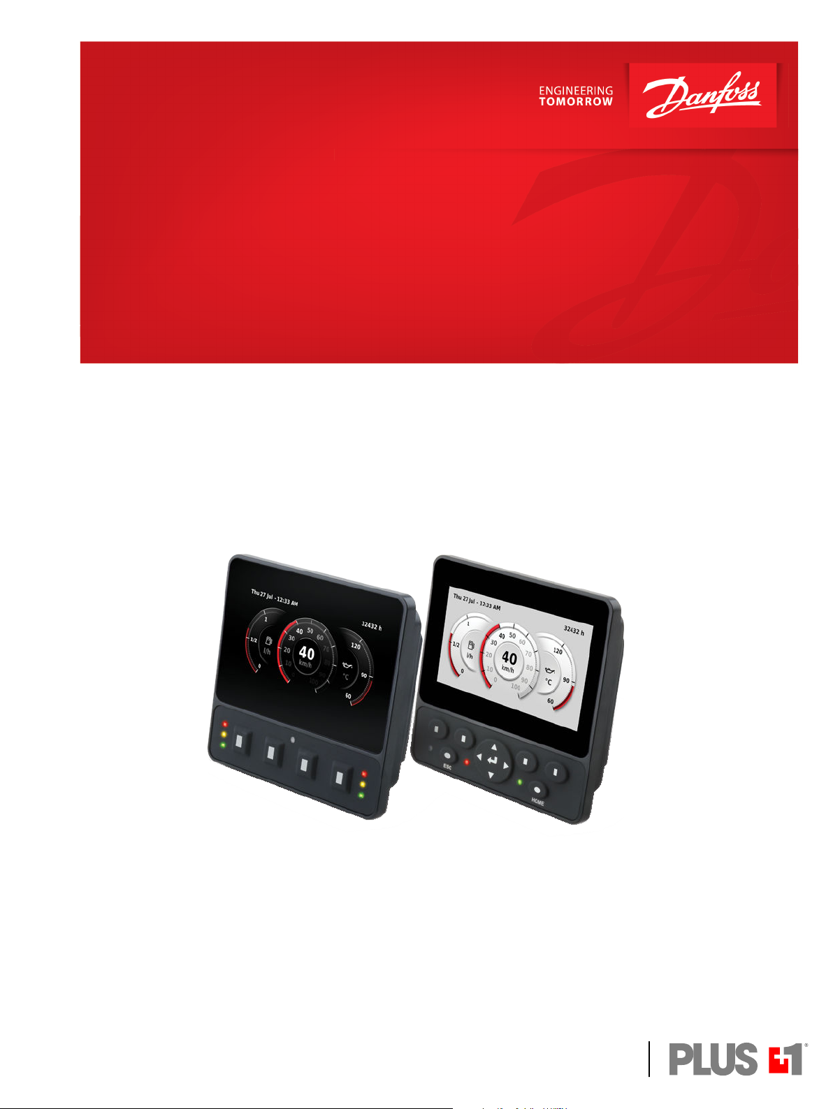
Engine Information Center (EIC)
DM430E Series Display
www.danfoss.com
Page 2
User Manual
DM430E Series Display - Engine Information Center (EIC) Software
Revision history Table of revisions
Date Changed Rev
December 2018 Minor change for print on demand, removed 2 blank pages at end of the manual for
required total pages divisive by 4.
December 2018 Added note in regards to keeping ambient light sensor area clean and uncovered for best
operation.
December 2018 First edition 0101
0103
0102
2 | © Danfoss | December 2018 AQ288937102741en-000103
Page 3

User Manual
DM430E Series Display - Engine Information Center (EIC) Software
Contents
User liability and safety statements
OEM responsibility........................................................................................................................................................................... 4
Safety statements.............................................................................................................................................................................4
Display operation guidelines..................................................................................................................................................4
Machine wiring guidelines...................................................................................................................................................... 5
Machine welding guidelines...................................................................................................................................................5
Overview
DM430E Series Display package................................................................................................................................................. 6
DM430E literature references.................................................................................................................................................6
Technical Information (TI)...................................................................................................................................................6
Data Sheet (DS).......................................................................................................................................................................6
API Specifications (API)........................................................................................................................................................6
PLUS+1® GUIDE User Manual.............................................................................................................................................6
Latest version of technical literature.............................................................................................................................. 6
The Engine Information Center (EIC).........................................................................................................................................6
Navigation using soft keys............................................................................................................................................................ 7
Initiate and inhibit regeneration.................................................................................................................................................7
Inhibit Regeneration action.....................................................................................................................................................8
Initiate Regeneration action....................................................................................................................................................8
TSC1 RPM setpoint......................................................................................................................................................................8
Main Menu
Basic Setup menu.............................................................................................................................................................................9
Brightness....................................................................................................................................................................................10
Color Theme............................................................................................................................................................................... 10
Time & Date................................................................................................................................................................................ 10
Language.....................................................................................................................................................................................11
Units...............................................................................................................................................................................................11
Diagnostics menu..........................................................................................................................................................................11
System Info................................................................................................................................................................................. 12
Fault Log...................................................................................................................................................................................... 12
Device List................................................................................................................................................................................... 12
Screen Setup menu.......................................................................................................................................................................13
Select Screens............................................................................................................................................................................ 13
Number of Screens...................................................................................................................................................................13
System Setup menu......................................................................................................................................................................14
Reset Defaults............................................................................................................................................................................ 14
CAN................................................................................................................................................................................................14
Display.......................................................................................................................................................................................... 15
PIN Setup..................................................................................................................................................................................... 15
Trip Reset..................................................................................................................................................................................... 16
Setup to monitor signals
Symbols for J1939 parameters..................................................................................................................................................21
LED indicators
Particulate filter lamp................................................................................................................................................................... 25
High exhaust system temperature lamp...............................................................................................................................25
Regeneration disabled lamp......................................................................................................................................................25
Installation and mounting
Mounting.......................................................................................................................................................................................... 26
Fastening...........................................................................................................................................................................................27
Pin assignments..............................................................................................................................................................................27
Ordering information
Model variants.................................................................................................................................................................................29
Model code.......................................................................................................................................................................................29
Model code key...............................................................................................................................................................................29
Related products............................................................................................................................................................................30
©
Danfoss | December 2018 AQ288937102741en-000103 | 3
Page 4

User Manual
DM430E Series Display - Engine Information Center (EIC) Software
User liability and safety statements
OEM responsibility
The OEM of a machine or vehicle in which Danfoss products are installed has the full responsibility for all
consequences that might occur. Danfoss has no responsibility for any consequences, direct or indirect,
caused by failures or malfunctions.
Danfoss has no responsibility for any accidents caused by incorrectly mounted or maintained
•
equipment.
Danfoss does not assume any responsibility for Danfoss products being incorrectly applied or the
•
system being programmed in a manner that jeopardizes safety.
All safety critical systems shall include an emergency stop to switch off the main supply voltage for
•
the outputs of the electronic control system. All safety critical components shall be installed in such a
way that the main supply voltage can be switched off at any time. The emergency stop must be easily
accessible to the operator.
Safety statements
Display operation guidelines
•
Disconnect your machine's battery power before connecting power and signal cables to the display.
•
Before doing any electrical welding on your machine, disconnect all power and signal cables
connected to the display.
•
Do not exceed the display power supply voltage ratings. Using higher voltages may damage the
display and can create a fire or electrical shock hazard.
•
Do not use or store the display where flammable gases or chemicals are present. Using or storing the
display where flammable gases or chemicals are present may cause an explosion.
•
Software configures the keypad buttons on the display. Do not use these buttons to implement
critical safety features. Use separate mechanical switches to implement critical safety features such as
emergency stops.
•
Design systems that use the display so that a communication error or failure between the display and
other units cannot cause a malfunction that might injure people or damage material.
•
The protective glass over the display screen will break if hit with a hard or heavy object. Install the
display to reduce the possibility of it being hit by hard or heavy objects.
•
Storing or operating a display in an environment that exceeds the display specified temperature or
humidity rating may damage the display.
•
Always clean the display with a soft, damp cloth. Use a mild dishwashing detergent as needed. To
avoid scratching and discoloring the display, do not use abrasive pads, scouring powders, or solvents
such as alcohol, benzene, or paint thinner.
•
Keep ambient light sensor area clean and uncovered for best operation.
•
Danfoss graphical displays are not user serviceable. Return the display to the factory in case of failure.
4 | © Danfoss | December 2018 AQ288937102741en-000103
Page 5

W
C
W
User Manual
DM430E Series Display - Engine Information Center (EIC) Software
User liability and safety statements
Machine wiring guidelines
Warning
Unintended movement of the machine or mechanism may cause injury to the technician or bystanders.
Improperly protected power input lines against over current conditions may cause damage to the
hardware. Properly protect all power input lines against over-current conditions. To protect against
unintended movement, secure the machine.
Caution
Unused pins on mating connectors may cause intermittent product performance or premature failure.
Plug all pins on mating connectors.
•
Protect wires from mechanical abuse, run wires in flexible metal or plastic conduits.
•
Use 85˚ C (185˚ F) wire with abrasion resistant insulation and 105˚ C (221˚ F) wire should be
considered near hot surfaces.
•
Use a wire size that is appropriate for the module connector.
•
Separate high current wires such as solenoids, lights, alternators or fuel pumps from sensor and other
noise-sensitive input wires.
•
Run wires along the inside of, or close to, metal machine surfaces where possible, this simulates a
shield which will minimize the effects of EMI/RFI radiation.
•
Do not run wires near sharp metal corners, consider running wires through a grommet when
rounding a corner.
•
Do not run wires near hot machine members.
•
Provide strain relief for all wires.
•
Avoid running wires near moving or vibrating components.
•
Avoid long, unsupported wire spans.
•
Ground electronic modules to a dedicated conductor of sufficient size that is connected to the
battery (-).
•
Power the sensors and valve drive circuits by their dedicated wired power sources and ground
returns.
•
Twist sensor lines about one turn every 10 cm (4 in).
•
Use wire harness anchors that will allow wires to float with respect to the machine rather than rigid
anchors.
Machine welding guidelines
Warning
High voltage from power and signal cables may cause fire or electrical shock, and cause an explosion if
flammable gasses or chemicals are present.
Disconnect all power and signal cables connected to the electronic component before performing any
electrical welding on a machine.
The following is recommended when welding on a machine equipped with electronic components:
•
Turn the engine off.
•
Remove electronic components from the machine before any arc welding.
•
Disconnect the negative battery cable from the battery.
•
Do not use electrical components to ground the welder.
•
Clamp the ground cable for the welder to the component that will be welded as close as possible to
the weld.
©
Danfoss | December 2018 AQ288937102741en-000103 | 5
Page 6
User Manual
DM430E Series Display - Engine Information Center (EIC) Software
Overview
DM430E Series Display package
Prior to use, ensure the following are included in the display package:
•
DM430E Series Display
•
Panel Seal Gasket
•
DM430E Series Display - Engine Information Center (EIC) User Manual
DM430E literature references
Reference literature
Literature title Literature type Literature number
DM430E Series PLUS+1® Mobile Machine Displays Technical Information BC00000397
DM430E Series PLUS+1® Mobile Machine Displays Data Sheet AI00000332
DM430E Series Display - Engine Information Center (EIC)
Software
PLUS+1® GUIDE Software User Manual AQ00000026
Technical Information (TI)
A TI is comprehensive information for engineering and service personnel to reference.
User Manual AQ00000253
Data Sheet (DS)
A DS is summarized information and parameters that are unique to a specific model.
API Specifications (API)
An API is specifications for programming variable settings.
API specifications are the definitive source of information regarding pin characteristics.
PLUS+1® GUIDE User Manual
The Operation Manual (OM) details information regarding the PLUS+1® GUIDE tool used in building PLUS
+1® applications. This OM covers the following broad topics:
How to use the PLUS+1® GUIDE graphical application development tool to create machine
•
applications
How to configure module input and output parameters
•
How to download PLUS+1® GUIDE applications to target PLUS+1® hardware modules
•
How to upload and download tuning parameters
•
How to use the PLUS+1® Service Tool
•
Latest version of technical literature
Comprehensive technical literature is online at www.danfoss.com
The Engine Information Center (EIC)
The DM430E comes installed with the powerful and flexible Danfoss Engine Information Center (EIC)
J1939 engine monitor software application. Use the application to customize the look and feel of your
individual engine monitoring needs by creating and controlling analog and digital display information in
the screen configurations that work best for your performance requirements.
Navigate through diagnostic information and configuration screens with ease by using the four contextdependent soft keys located at the front of the display. Choose from more than 4500 different
monitoring parameter profiles to customize the DM430E.
6 | © Danfoss | December 2018 AQ288937102741en-000103
Page 7
Inhibit
Switch
Initiate
Switch
TSC1RPM
Set Point
Exit/Back
One Screen
Exit/Back
One Screen
NavigateUpNavigate
Down
Select
Next
Menu
NavigateUpNavigate
Down
Main
Menu
Decrement Increment
User Manual
DM430E Series Display - Engine Information Center (EIC) Software
Overview
Up to four signals can be monitored on each screen. Use the EIC software to configure the DM430E for
alarms and alerts.
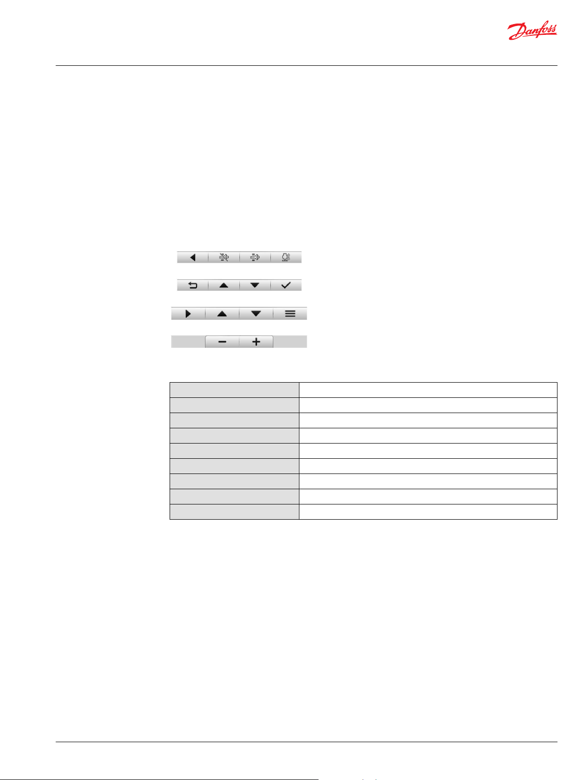
Navigation using soft keys
The DM430E is controlled by navigation through a set of four soft keys located at the lower front of the
display. The keys are context dependent. Soft key selection options are displayed above each key and are
dependent on the current navigation location within the engine monitor software program. As a general
rule, the far right soft key is the selector button and the far left soft key is the step back one screen key. To
optimize full screen use, the on-screen selections are not displayed when not in use. Press any soft key to
display current selection options.
Navigation using soft keys
Initiate and inhibit regeneration
Screen navigation
Navigate Up
Navigate Down
Main Menu
Exit/Back one screen
Select
Next Menu
Inhibit Regen
Initiate Regen
Increment/decrement
Press to move up through menu items or screens
Press to move down through menu items or screens
Press to go to Main Menu screen
Press to go back one screen
Press to accept selection
Press to select next digit or screen element
Press to force regeneration of particulate filter
Press to inhibit particulate filter regeneration
Press to increment or decrement value
While EIC DM430E is displaying one of the monitor screens, pressing any soft key will show the available
navigation actions in an action menu. There are two separate action menus on this level, the first one to
appear contains the following actions (from left to right).
Next Menu
•
Navigate Up
•
Navigate Down
•
Main Menu
•
Selecting Next Menu will display the second action menu with Inhibit switch (Inhibit Regeneration),
Initiate switch (Initiate Regeneration) and RPM Set Point. Pressing it again will show the first set of
actions once more. Selecting Navigate Up and Navigate Down will allow navigation between signal
monitoring screens. Selecting Main Menu will display the DM430E set up options. If no soft keys are
pressed and released for 3 seconds while the action menu is shown, the menu will disappear and the
actions are no longer available. Pressing (and releasing) any soft key will activate the first menu once
more.
©
Danfoss | December 2018 AQ288937102741en-000103 | 7
Page 8

User Manual
DM430E Series Display - Engine Information Center (EIC) Software
Overview
Inhibit Regeneration action
If the user selects the Inhibit Regeneration action while the action menu is being displayed the same
function as described in Initiate Regeneration action will be executed, with the following.
Bit 0 (out of 0-7) in byte 5 (out of 0-7) is set to 1 (true).
•
The pop up reads Inhibit Regen.
•
The acknowledgment lights up the Regeneration Inhibit LED.
•
Initiate Regeneration action
If the user selects the Initiate Regeneration action while the action menu is being displayed; bit 2 (out of
0-7) in byte 5 (out of 0-7) will be set to 1 (true) in the J1939 message PGN 57344 bound for the engine.
This change prompts the message to be transmitted. The bit will stay like this for the duration of the soft
key press or for the 3 second countdown to soft key inactivity, whichever occurs first. The bit is then reset
to 0 (false).
The soft key press also prompts the display to show a pop up lasting for 3 seconds. This popup simply
says Initiate Regen. If the display does not receive an acknowledgment from the engine on the change
to message PGN 57344 the last half of the pop up will read No Engine Signal. This acknowledgment is
the command that lights up the Initiate Regeneration LED on the display unit housing.
TSC1 RPM setpoint
The TSC1 message sends the RPM requirement for the engine.
8 | © Danfoss | December 2018 AQ288937102741en-000103
Page 9
User Manual
DM430E Series Display - Engine Information Center (EIC) Software
Main Menu
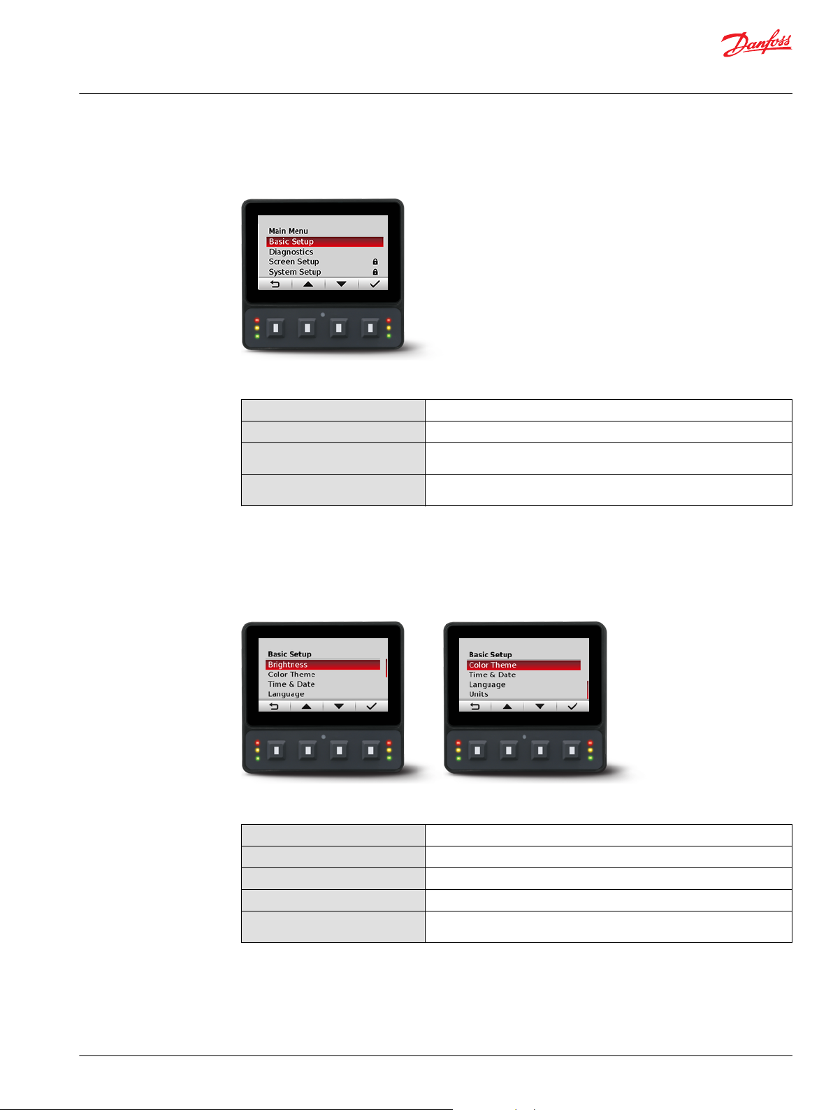
Use the Main Menu as the starting point for configuring the DM430E Series Display.
Main Menu screen
Main Menu
Basic Setup
Diagnostics
Screen Setup
System Setup
Use to set Brightness, Color Theme, Time & Date, Language, Units
Use to view system, fault log and device information
Use to select screens, number of screens and parameters (can be PIN
protected)
Use to reset defaults and trip information, access CAN information, select
display settings, and configure PIN settings
Basic Setup menu
Use Basic Setup to set brightness, color theme, time & date, language, and units for the DM430E Series
Display.
Basic Setup screen
Basic Setup menu
Brightness
Color Theme
Time & Date
Language
Units
Use to adjust brightness level of the screen
Use to set background color of display
Use to set time, date, and time and date styles
Use to set the system language, default language is English
Use to set speed, distance, pressure, volume, mass, temperature and flow
settings
©
Danfoss | December 2018 AQ288937102741en-000103 | 9
Page 10
User Manual
DM430E Series Display - Engine Information Center (EIC) Software
Main Menu
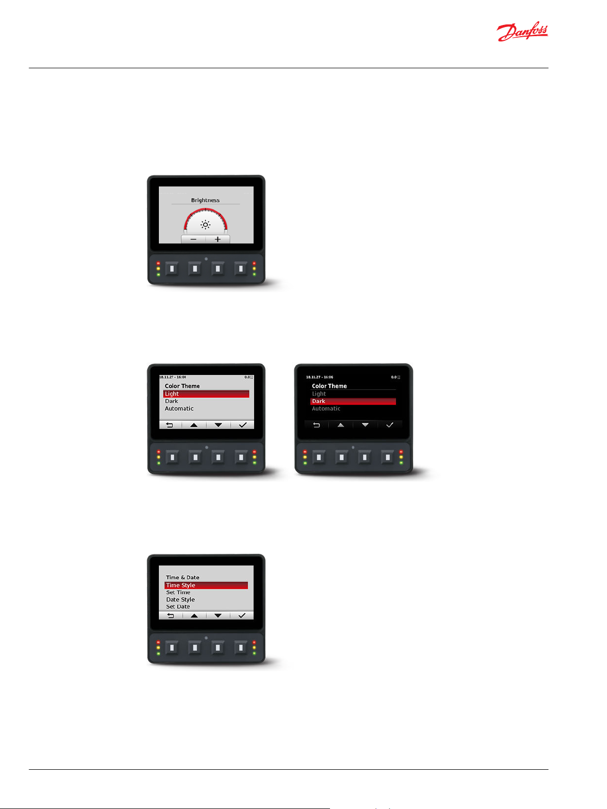
Brightness
Use the minus (-) and plus (+) soft keys to adjust display screen brightness. After 3 seconds of inactivity
the screen will go back to basic setup.
Brightness screen
Color Theme
Use to select between 3 options of Light, Dark and Automatic.
Color Theme screen
Time & Date
Use up, down, select, and next soft keys to set time style, time, date style, and date.
Time & Date screen
10 | © Danfoss | December 2018 AQ288937102741en-000103
Page 11

User Manual
DM430E Series Display - Engine Information Center (EIC) Software
Main Menu
Language
Use up, down and select soft keys to select program language. Available languages are English, Spanish,
French, German, Italian, Swedish and Portuguese.
Language screen
Units
Use up, down, and select soft keys to define units of measurement.
Diagnostics menu
Units of measurement
Speed
Distance
Pressure
Volume
Mass
Temperature
Flow
kph, mph
km, miles
kPa, bar, psi
litre, gal, igal
kg, lbs
°C, °F
lph, gph, igph
Use to obtain system info, fault log entries, and device information.
Diagnostics screen
Diagnostics menu
System Info
Fault Log
Device List
©
Danfoss | December 2018 AQ288937102741en-000103 | 11
Use to display hardware, software, system, and node information for
connected devices
Use to view and monitor current and previous fault information
Use to display list of all currently connected J1939 devices
Page 12

User Manual
DM430E Series Display - Engine Information Center (EIC) Software
Main Menu
System Info
The System Info screen contains hardware serial number, software version, node number and ROP
version.
System Info screen example
Fault Log The Fault Log screen contains saved and stored fault information. Select either Active Faults or Previous
Faults to monitor fault activity. Select specific faults to list more information.
Fault Log screen
Active faults
Select Active Faults to display all active faults on the CAN network.
Previous faults
Select Previous Faults to display all previously active faults on the CAN network.
Device List
The Device List screen lists J1939 devices and addresses that are currently being monitored on the
network.
12 | © Danfoss | December 2018 AQ288937102741en-000103
Page 13

User Manual
DM430E Series Display - Engine Information Center (EIC) Software
Main Menu
Screen Setup menu
Use Screen Setup to select individual screens for setup, and number of signal screens.
Screen Setup menu
Select Screens
Number of Screens
Select screen to set up signal information, screens available are dependent
on Number of Screens selection
Select 1 to 4 screens for information display
Select Screens
Select screen to customize. For screen set up details, see Setup to monitor signals.
Select Screens example
Number of Screens
Select number of screens for display. Choose from 1 to 4 screens. For screen set up details, see Setup to
monitor signals.
Number of Screens example
©
Danfoss | December 2018 AQ288937102741en-000103 | 13
Page 14

User Manual
DM430E Series Display - Engine Information Center (EIC) Software
Main Menu
System Setup menu
Use System Setup to monitor and control application systems.
System Setup menu
Reset Defaults
CAN
Display
PIN Setup
Trip Reset
Use to reset all system information to the default settings
Use to customize CAN settings
Use to customize display settings
Use to customize PIN settings
Use to reset trip information
Reset Defaults
Select Reset Defaults to reset all EIC settings to original factory default settings.
CAN
Use the CAN settings screen to make the following selections.
14 | © Danfoss | December 2018 AQ288937102741en-000103
Page 15

User Manual
DM430E Series Display - Engine Information Center (EIC) Software
Main Menu
CAN settings menu
Fault Popup
Conversion Method
Engine Address
Engine Type
Engine DMs Only
Transmit TSC1
JD Interlock
Display
Select on/off to enable/disable pop-up messages.
Select 1, 2 or 3 to determine how to interpret nonstandard fault messages. Consult engine manufacturer
for correct setting.
Select engine address. Selection range is 0 to 253.
Select from a list of predetermined engine types.
Only accepts fault codes or J1939 DM messages from the
engine.
Enable to send the TSC1 (Torque Speed Control 1)
message.
Transmit John Deere Interlock message required for
regeneration.
Display Setting
Startup Screen
Buzzer Output
Force Return to Gauges
Demo Mode
Select to enable/disable logo display at startup.
Select to enable/disable warning buzzer functionality.
After 5 minutes of inactivity returns to main Gauge.
Select on/off to enable demonstration mode.
PIN Setup
To reduce the potential for errors, Screen Setup and System Setup menu options can only be accessed
after entering a PIN code.
The default code is 1-2-3-4. To change PIN code go to System Setup > PIN Setup > Change PIN Code.
PIN Setup
©
Danfoss | December 2018 AQ288937102741en-000103 | 15
Page 16

User Manual
DM430E Series Display - Engine Information Center (EIC) Software
Main Menu
Trip Reset
Select Yes to reset all trip data.
16 | © Danfoss | December 2018 AQ288937102741en-000103
Page 17

User Manual
DM430E Series Display - Engine Information Center (EIC) Software
Setup to monitor signals
The following steps are for screen setup. Steps 1 through 3 are for selecting number of screens and
screen types and 4 through 7 are for selecting J1939 monitor controls.
For J1939 parameters available, function and symbols, reference Symbols for J1939 parameters.
1. Navigate to Main Menu > Screen Setup > Number of Screens. Select from one to four screens for
signal monitoring.
2. Navigate to Main Menu > Screen Setup > Select Screens and select screen to customize.
3. Select screen type for each of the screens selected. There are four screen variants.
Screen type 1
Type 1 is a two-up screen view with two signal capacity.
Screen type 2
©
Danfoss | December 2018 AQ288937102741en-000103 | 17
Page 18

User Manual
DM430E Series Display - Engine Information Center (EIC) Software
Setup to monitor signals
Type 2 is a three-up view with one large signal display capacity and behind it, partially visible, are two
small signal display capacities.
Screen type 3
Type 3 is a three-up view with one large and two small signal display capacities.
Screen type 4
Type 4 is a four-up view with four small signal display capacities.
For more screen type customization it is possible to configure the small signal displays by choosing from
three styles.
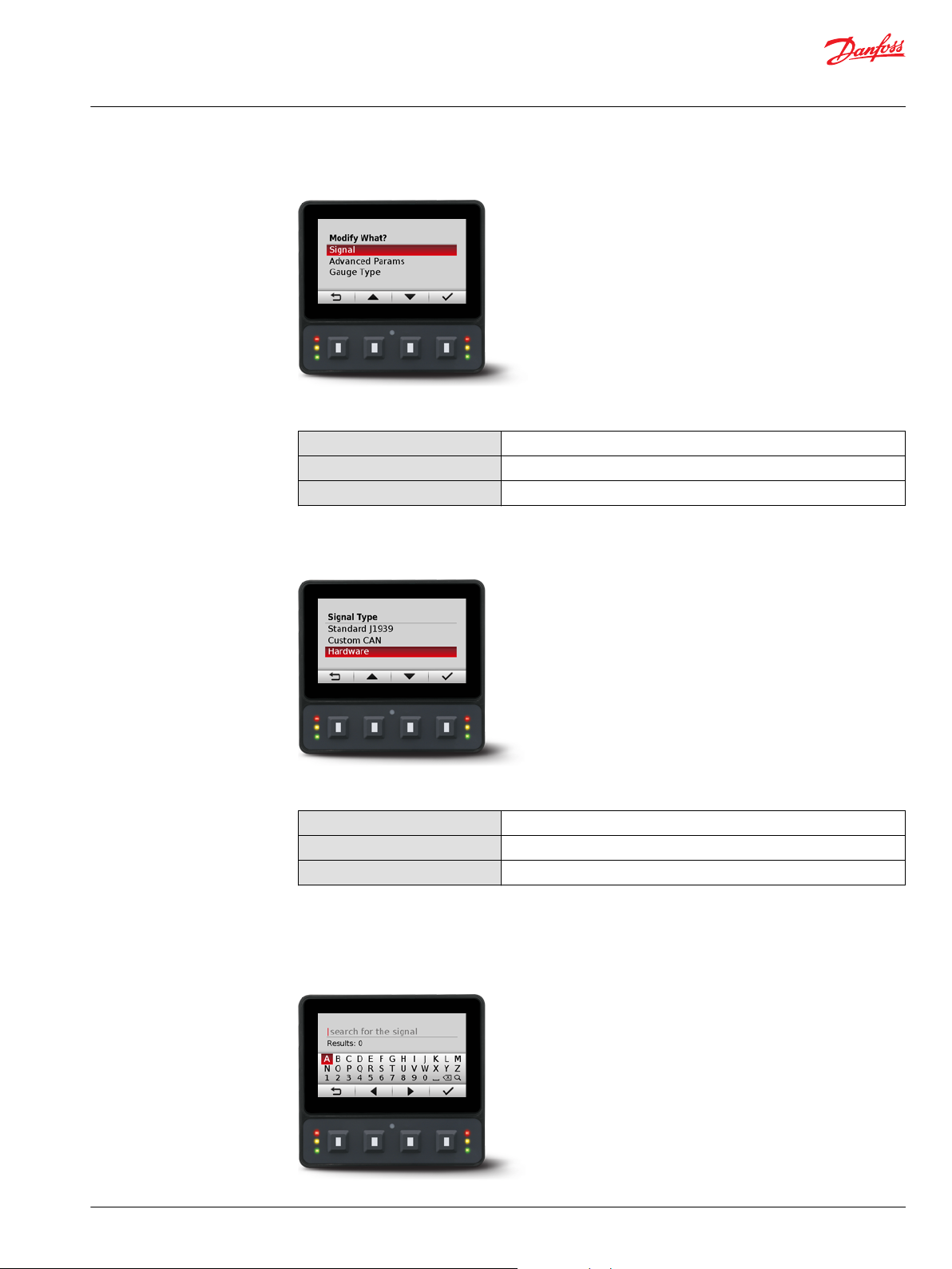
4. After choosing the gauge to modify, press select key, a screen called Modify What? will open.
Within this screen it is possible to modify the signal and advanced parameters. Additionally, for
screen type 3 and 4, the gauge type can also be modified.
18 | © Danfoss | December 2018 AQ288937102741en-000103
Page 19
User Manual
DM430E Series Display - Engine Information Center (EIC) Software
Setup to monitor signals
Modify What? screen
Modify What?
Signal
Advanced Parameters
Gauge Type
5. When modifying signal, 3 signal types are available.
Signal Type screen
Use to define the signal you would like to display.
Use to define gauge icon, range, multiplier and tick settings.
Use to define gauge appearance.
Signal Type
Standard J1939
Custom CAN
Hardware
Choose from over 4500 signal types.
Choose a CAN signal.
Choose hardware specific signals.
6. When choosing Standard J1939, it is possible to search for available signals. Choose between Text,
PGN and SPN search types. Use the left and right arrow soft keys to cycle through the alphabet and
enter the signal.
Search for the signal screen
©
Danfoss | December 2018 AQ288937102741en-000103 | 19
Page 20
User Manual
DM430E Series Display - Engine Information Center (EIC) Software
Setup to monitor signals
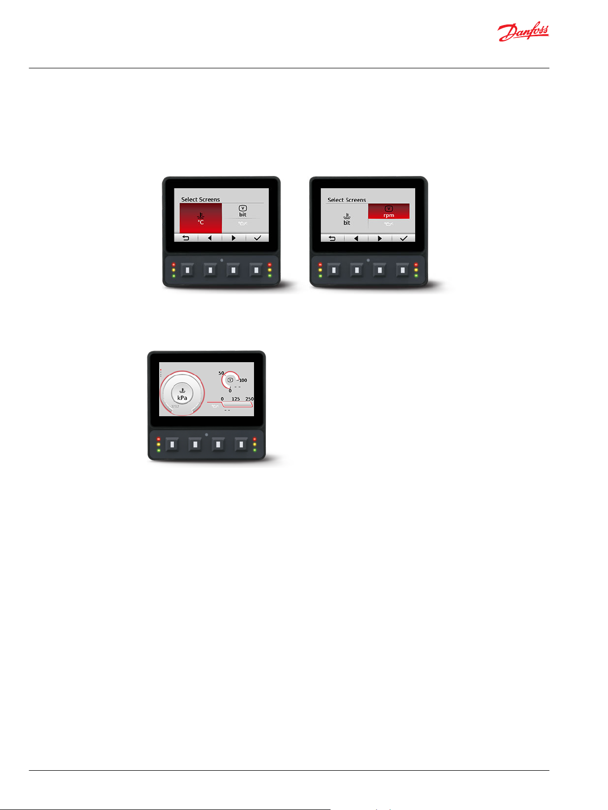
7. After making a signal selection, press the right arrow soft key to go to the next selection area.
Use left arrow, right arrow, and next soft keys to select signal monitoring screen.
•
Use the right arrow soft key to rotate through the selections in a clockwise rotation.
•
Examples of screen signal selections
Complete screen signal selections then press the back symbol soft key to return to previous menus.
8.
Navigate back for more screen selections or press the back soft key until you reach the Main Screen.
Example of screen setup
20 | © Danfoss | December 2018 AQ288937102741en-000103
Page 21

User Manual
DM430E Series Display - Engine Information Center (EIC) Software
Setup to monitor signals
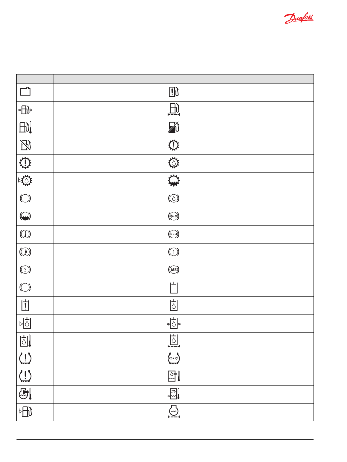
Symbols for J1939 parameters
The following table lists symbols for the J1939 engine and transmission parameters that are available and
can be monitored.
Symbols for the J1939 engine and transmission parameters
Symbol Name/Function Symbol Name/Function
Temperature Engine coolant temperature
Battery charging condition Engine oil
Engine Fuel economy
Primary voltage Oil; fluid
Transmission Transmission
Transmission oil pressure Transmission oil temperature
Transmission oil temperature Transmission oil filter
Engine intake air filter; engine combustion air filter Hour meter; elapsed operating hours
Hand accelerator control; hand throttle Engine failure; engine malfunction
Engine lubricating oil Engine lubricating oil level
Engine lubricating oil pressure Engine lubricating oil temperature
Engine lubricating oil filter Engine coolant
Engine coolant level Engine coolant pressure
Engine coolant temperature Engine intake; combustion air
Engine intake; combustion air pressure Engine intake; combustion air temperature
Engine exhaust gas Engine exhaust gas pressure
Engine exhaust gas temperature Engine start
Engine stop Engine rotational speed (revolutions per minute)
©
Danfoss | December 2018 AQ288937102741en-000103 | 21
Page 22
User Manual
DM430E Series Display - Engine Information Center (EIC) Software
Setup to monitor signals
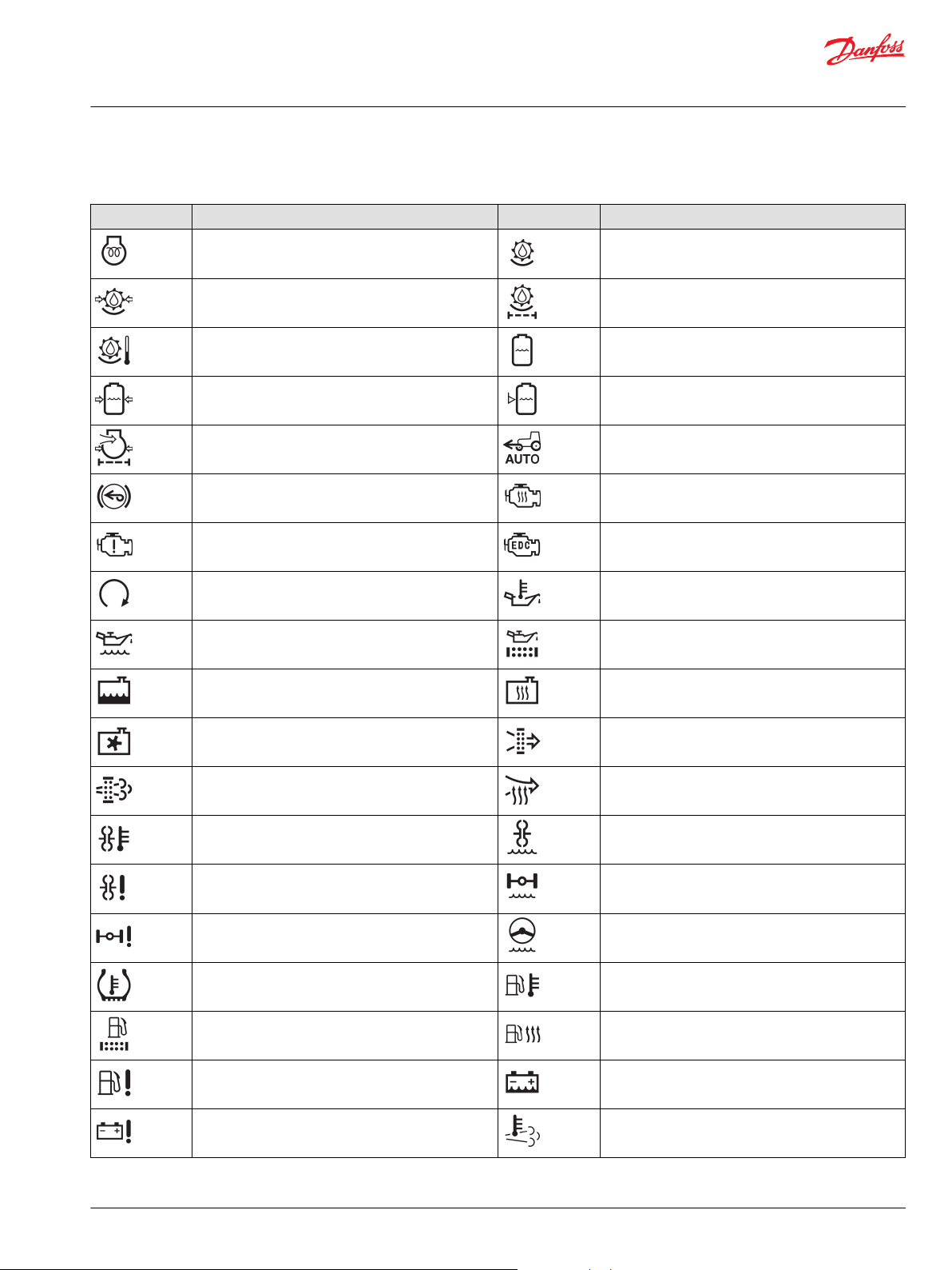
Symbols for the J1939 engine and transmission parameters (continued)
Symbol Name/Function Symbol Name/Function
Heat exchanger, coolant fluid radiator; radiator Fuel system failure; malfunction
Fuel pressure Fuel filter
Fuel temperature Fuel shut-off
Fuel shut-off Transmission failure/malfunction
Transmission failure/malfunction Transmission oil
Transmission oil level Transmission oil level
Brake system Brake oil/fluid
Brake fluid level Brake system pressure
Brake system temperature; brake temperature Brake system filter
Brake system temperature; brake temperature Brake system, first circuit
Brake system, second circuit Anti-lock brake system, failure
Worn brake linings Hydraulic system
Hydraulic system failure/malfunction Hydraulic oil
Hydraulic oil level Hydraulic oil pressure
Hydraulic oil temperature Hydraulic oil filter
Tire failure/malfunction Tire pressure
Tire failure/malfunction Liquid cooled oil cooler, oil outlet temperature
Engine-exhaust-gas coolant temperature Charge air cooler, coolant inlet temperature
Fuel level Engine coolant filter
22 | © Danfoss | December 2018 AQ288937102741en-000103
Page 23
User Manual
DM430E Series Display - Engine Information Center (EIC) Software
Setup to monitor signals
Symbols for the J1939 engine and transmission parameters (continued)
Symbol Name/Function Symbol Name/Function
Engine, electrical preheat (low temperature start aid) Separator-drive oil
Separator-drive oil pressure Separator-drive oil filter
Separator-drive oil temperature Spray solution tank
Spray solution tank pressure Spray solution tank level
Engine air filter pressure Tractor, front-wheel drive, automatic operation
Tractor, front-wheel drive, braking Road vehicle, engine heating
Road vehicle, engine failure/malfunction Road vehicle, electronic diesel control
Road vehicle, engine start Road vehicle, engine oil temperature
Road vehicle, engine oil level Road vehicle, engine oil filter
Road vehicle, engine coolant level Road vehicle, engine coolant heating
Road vehicle, engine coolant fan Road vehicle, engine inlet air filter
Road vehicle, engine emission filter Road vehicle, engine inlet air preheat
Transmission converter temperature Transmission converter fluid level
Transmission converter failure Axle fluid level
Axle failure Steering fluid level
Tire temperature Road vehicle, fuel temperature
Road vehicle, fuel filter Fuel heating
Road vehicle, fuel system failure Battery fluid level
Battery failure Engine emission system temperature; diesel particulate
©
Danfoss | December 2018 AQ288937102741en-000103 | 23
filter, regeneration underway
Page 24
User Manual
DM430E Series Display - Engine Information Center (EIC) Software
Setup to monitor signals
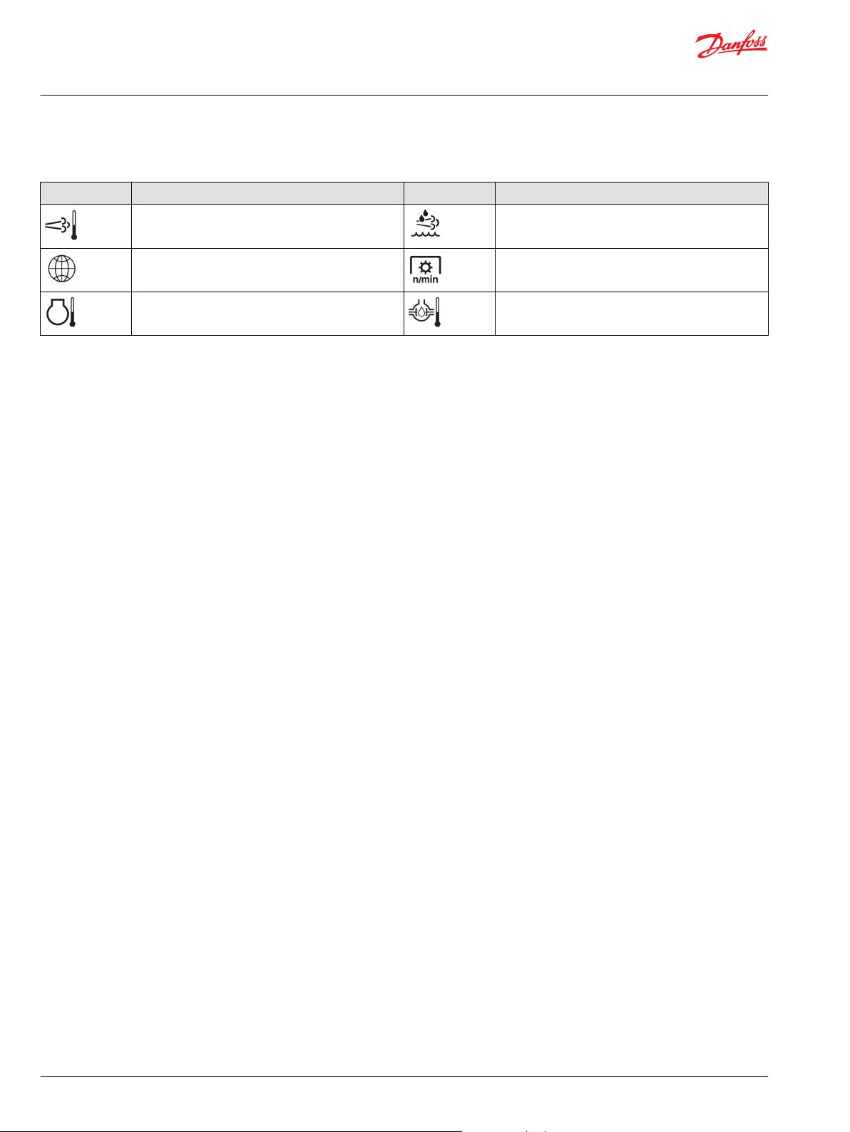
Symbols for the J1939 engine and transmission parameters (continued)
Symbol Name/Function Symbol Name/Function
Engine emissions system temperature; diesel
particulate filter, regeneration underway
Latitude and longitude Power take-off (PTO), rotational speed
Engine system temperature Differential gear oil temperature
Diesel exhaust fluid (DEF); selective catalyst reduction
(SCR) fluid
24 | © Danfoss | December 2018 AQ288937102741en-000103
Page 25

User Manual
DM430E Series Display - Engine Information Center (EIC) Software
LED indicators
Particulate filter lamp
Stage 1 The right Amber LED indicates the initial need for regeneration.
The lamp is on solid.
Stage 2 The right Amber LED indicates an urgent regeneration.
Lamp flashes with 1 Hz.
Stage 3 Same as Stage 2 but check engine lamp will also turn on.
High exhaust system temperature lamp
The left Amber LED indicates the increase of exhaust system temperature due to regeneration.
Regeneration disabled lamp
The left Amber LED indicates that the regeneration disabled switch is active.
©
Danfoss | December 2018 AQ288937102741en-000103 | 25
Page 26

4 x R3
R13
115.40 [4.54]
107.50 [4.23]
104.50 [4.11]
99.50 [3.92]
1
2
3
A B
User Manual
DM430E Series Display - Engine Information Center (EIC) Software
Installation and mounting
Mounting
Recommended mounting procedure
mm [in]
Callout Description
A Panel opening for mounting on surface A
B Panel opening for mounting on surface B
1 Panel seal
2 Panel bracket
3 Four screws
26 | © Danfoss | December 2018 AQ288937102741en-000103
Page 27

C
7.5 [0.3]
Pin 1
Pin 6
Pin 12Pin 7
User Manual
DM430E Series Display - Engine Information Center (EIC) Software
Installation and mounting
Fastening
Caution
•
Use of non-recommended screws can cause damage to housing.
•
Excessive screw torque force can cause damage to housing. Maximum torque: 0.9 N m (8 in-lbs).
•
Reassembly with self-tapping screws can damage existing threads in housing.
•
Oversized panel cutouts can jeopardize product IP rating.
•
Ensure the vent is not covered. This excludes the RAM mount option.
Fastening hole depth
mm [in]
Fastening hole depth: 7.5 mm (0.3 in). Standard M4x0.7 screw may be used.
Maximum torque: 0.9 N m (8 in-lbs).
Pin assignments
12 pin DEUTSCH connector
DEUTSCH DTM06-12SA 12 pin
C1 pin DM430E-0-x-x-x DM430E-1-x-x-x DM430E-2-x-x-x
1 Power ground - Power ground - Power ground 2 Power supply + Power supply + Power supply +
3 CAN 0 + CAN 0 + CAN 0 +
4 CAN 0 - CAN 0 - CAN 0 5 AnIn/CAN 0 Shield AnIn/CAN 0 Shield AnIn/CAN 0 Shield
6 DigIn/AnIn DigIn/AnIn DigIn/AnIn
©
Danfoss | December 2018 AQ288937102741en-000103 | 27
Page 28

Pin 6
Pin 8
Pin 1
Pin 2
Pin 3
Pin 4
Pin 5
Pin 7
User Manual
DM430E Series Display - Engine Information Center (EIC) Software
Installation and mounting
DEUTSCH DTM06-12SA 12 pin (continued)
C1 pin DM430E-0-x-x-x DM430E-1-x-x-x DM430E-2-x-x-x
7 DigIn/AnIn DigIn/AnIn DigIn/AnIn
8 DigIn/AnIn CAN 1+ Sensor power
9 DigIn/AnIn CAN 1- Secondary power input
10 Multifunction input (DigIn/AnIn/Freq/4-20
11 Multifunction input (DigIn/AnIn/Freq/4-20
12 Digital out (0.5A sinking) Digital out (0.5A sinking) Digital out (0.5A sinking)
*
From controller (requires surge protection).
mA/Rheostat)
mA/Rheostat)
8 pin M12 connector
Multifunction input (DigIn/AnIn/Freq/4-20
mA/Rheostat)
Multifunction input (DigIn/AnIn/Freq/4-20
mA/Rheostat)
Multifunction input (DigIn/AnIn/Freq/4-20
mA/Rheostat)
Multifunction input (DigIn/AnIn/Freq/4-20
mA/Rheostat)
*
M12-A 8 pin
C2 pin Function
1 Device Vbus
2 Device data 3 Device data +
4 Ground
5 Ground
6 RS232 Rx
7 RS232 Tx
8 NC
28 | © Danfoss | December 2018 AQ288937102741en-000103
Page 29

User Manual
DM430E Series Display - Engine Information Center (EIC) Software
Ordering information
Model variants
Part number Order code Description
11197958 DM430E-0-0-0-0 4 Buttons, I/O
11197973 DM430E-1-0-0-0 4 Buttons, 2-CAN
11197977 DM430E-2-0-0-0 4 Buttons, Sensor Power, Secondary Power Input
11197960 DM430E-0-1-0-0 4 Buttons, I/O, USB/RS232
11197974 DM430E-1-1-0-0 4 Buttons, 2-CAN, USB/RS232
11197978 DM430E-2-1-0-0 4 Buttons, Sensor Power, Secondary Power Input, USB/RS232
11197961 DM430E-0-0-1-0 Navigation Buttons, I/O
11197975 DM430E-1-0-1-0 Navigation Buttons, 2-CAN
11197979 DM430E-2-0-1-0 Navigation Buttons, Sensor Power, Secondary Power Input
11197972 DM430E-0-1-1-0 Navigation Buttons, I/O, USB/RS232
11197976 DM430E-1-1-1-0 Navigation Buttons, 2-CAN, USB/RS232
11197980 DM430E-2-1-1-0 Navigation Buttons, Sensor Power, Secondary Power Input, USB/RS232
11197981 DM430E-0-0-0-1 4 Buttons, I/O, EIC Application
11197985 DM430E-1-0-0-1 4 Buttons, 2-CAN, EIC Application
11197989 DM430E-2-0-0-1 4 Buttons, Sensor Power, Secondary Power Input, EIC Application
11197982 DM430E-0-1-0-1 4 Buttons, I/O, USB/RS232, EIC Application
11197986 DM430E-1-1-0-1 4 Buttons, 2-CAN, USB/RS232, EIC Application
11197990 DM430E-2-1-0-1 4 Buttons, Sensor Power, Secondary Power Input, USB/RS232, EIC Application
11197983 DM430E-0-0-1-1 Navigation Buttons, I/O, EIC Application
11197987 DM430E-1-0-1-1 Navigation Buttons, 2-CAN, EIC Application
11197991 DM430E-2-0-1-1 Navigation Buttons, Sensor Power, Secondary Power Input, EIC Application
11197984 DM430E-0-1-1-1 Navigation Buttons, I/O, USB/RS232, EIC Application
11197988 DM430E-1-1-1-1 Navigation Buttons, 2-CAN, USB/RS232, EIC Application
11197992 DM430E-2-1-1-1 Navigation Buttons, Sensor Power, Secondary Power Input, USB/RS232, EIC Application
Model code
A B C D E
DM430E
Model code key
A—Model name Description
DM430E 4.3" Color Graphical Display
B—Inputs/Outputs Description
0 1 CAN Port, 4DIN/AIN, 2 MFIN
1 2 CAN Port, 2DIN/AIN, 2 MFIN
2 1 CAN Port, 2DIN/AIN, 2 MFIN, Sensor Power
C—M12 connector Description
0 No USB Device, No RS232
1 USB Device, RS232
©
Danfoss | December 2018 AQ288937102741en-000103 | 29
Page 30

User Manual
DM430E Series Display - Engine Information Center (EIC) Software
Ordering information
D—Button Pads Description
0 4 Buttons, 6 LEDs
1 Navigation buttons, 2 Dual-color LEDs
Related products
E—Application key
(EIC Application)
0 No Application Key
1 Application Key (EIC Application)
Description
Connector bag assembly
10100944
DEUTSCH 12-pin Connector Kit (DTM06-12SA)
Connector and cable kit
11130518
11130713
Cable, M12 8-Pin to USB Device
Cable, M12 8-Pin to Lead Wires
Connection tools
10100744
10100745
DEUTSCH stamped contacts terminal crimp tool, size 20
DEUTSCH solid contacts terminal crimp tool
Mounting kit
11198661
Panel mounting kit
Software
11179523
(annual renewal with
11179524 to keep the
software updates)
Online
*
Requires a model with Application Key. See Model variants for model codes.
PLUS+1® GUIDE Professional Software (includes 1 year of software updates, a single user
license, Service and Diagnostic Tool and Screen Editor)
J1939 CAN EIC Engine Monitor Software
*
30 | © Danfoss | December 2018 AQ288937102741en-000103
Page 31

User Manual
DM430E Series Display - Engine Information Center (EIC) Software
©
Danfoss | December 2018 AQ288937102741en-000103 | 31
Page 32

Danfoss
Power Solutions GmbH & Co. OHG
Krokamp 35
D-24539 Neumünster, Germany
Phone: +49 4321 871 0
Danfoss
Power Solutions ApS
Nordborgvej 81
DK-6430 Nordborg, Denmark
Phone: +45 7488 2222
Danfoss
Power Solutions (US) Company
2800 East 13th Street
Ames, IA 50010, USA
Phone: +1 515 239 6000
Danfoss
Power Solutions Trading
(Shanghai) Co., Ltd.
Building #22, No. 1000 Jin Hai Rd
Jin Qiao, Pudong New District
Shanghai, China 201206
Phone: +86 21 3418 5200
Products we offer:
Comatrol
www.comatrol.com
Turolla
www.turollaocg.com
Hydro-Gear
www.hydro-gear.com
Daikin-Sauer-Danfoss
www.daikin-sauer-danfoss.com
DCV directional control
•
valves
Electric converters
•
Electric machines
•
Electric motors
•
Hydrostatic motors
•
Hydrostatic pumps
•
Orbital motors
•
PLUS+1® controllers
•
PLUS+1® displays
•
PLUS+1® joysticks and
•
pedals
PLUS+1® operator
•
interfaces
PLUS+1® sensors
•
PLUS+1® software
•
PLUS+1® software services,
•
support and training
Position controls and
•
sensors
PVG proportional valves
•
Steering components and
•
systems
Telematics
•
Danfoss Power Solutions is a global manufacturer and supplier of high-quality hydraulic and
electric components. We specialize in providing state-of-the-art technology and solutions
that excel in the harsh operating conditions of the mobile off-highway market as well as the
marine sector. Building on our extensive applications expertise, we work closely with you to
ensure exceptional performance for a broad range of applications. We help you and other
customers around the world speed up system development, reduce costs and bring vehicles
and vessels to market faster.
Danfoss Power Solutions – your strongest partner in mobile hydraulics and mobile
electrification.
Go to www.danfoss.com for further product information.
We offer you expert worldwide support for ensuring the best possible solutions for
outstanding performance. And with an extensive network of Global Service Partners, we also
provide you with comprehensive global service for all of our components.
Local address:
Danfoss can accept no responsibility for possible errors in catalogues, brochures and other printed material. Danfoss reserves the right to alter its products without notice. This also applies to products
already on order provided that such alterations can be made without subsequent changes being necessary in specifications already agreed.
All trademarks in this material are property of the respective companies. Danfoss and the Danfoss logotype are trademarks of Danfoss A/S. All rights reserved.
©
Danfoss | December 2018 AQ288937102741en-000103
 Loading...