

MAKING MODERN LIVING POSSIBLE
DLX
User Guide
DLX 2.0 UL - DLX 2.9 UL - DLX 3.8 UL - DLX 4.4 UL
SOLAR INVERTERS
fo
r
T
a
e
a
D
o
e
a
u
n
o
o
f
s
c
i
g
r
s
n
e
d
t
r
o
i
r
e
,
s
u
c
o
S
,
c
h
a
D
r
0
0
Dan
othe
his
mad
All tr
the
ss can acc
printed m
lso applies
without s
demarks i
anfoss log
pt no resp
terial. Dan
to product
bsequent
this mater
type are re
nsibility fo
oss reserve
already on
hanges bei
al are prop
istered tra
Copyrigh
possible e
the right t
order prov
g necessa
rty of the r
emarks of
©: Danfoss
rors in cata
alter its pr
ded that s
y in specifi
spective c
Danfoss A/
2012
logues, bro
oducts wit
ch alteratio
ations alre
mpanies.
. All rights
hures and
out notice.
ns can be
dy agreed.
anfoss and
eserved.
II
U
ser Guide DLX UL
series L00410625-
1
u
t
U
o
i
o
f
t
T
n
g
n
n
T
e
o
T
r
T
e
,
V
n
s
i
o
n
s
n
n
c
a
a
,
7
O
N
H
r
a
n
m
i
u
o
e
h
t
t
A
U
n
a
u
a
s
d
t
p
a
h
S
O
T
o
a
n
a
n
p
e
m
w
g
!
T
e
a
a
y
n
d
m
e
G
u
e
E
e
N
w
t
g
h
t
c
n
G
e
b
r
!
Safe
This
thor
Ignor
Qual
Pers
quali
SA
y Instructio
ser Guide co
ughly read a
ing these in
fied person
ns involved
ied, and foll
IMP
I
E T
s
ntains impo
nd followed
tructions m
s
n installatio
w the instru
RT
STR
ESE
tant safety i
prior to inst
y have serio
, operation
ctions in thi
NT
CTI
INS
structions f
llation, oper
s conseque
nd mainten
User Guide.
AFE
NS
RUC
r DLX UL inv
tion and m
ces and ma
nce of the i
TY
IO
rter series,
intenance o
invalidate
verter must
S!
hich must
f the inverte
he warranty
be suitably
e
.
Safe
y Protectio
he i
instal
lation, opera
isolat
ion between
prefe
rence and e
volta
and I
War
hre
pers
nal injury an
CAU
Elect
he
lectrical inst
(NEC)
verter offer
e or freque
terruption
ing Signs
different w
ION appear
ical Codes
ANSI/NFPA
a maximu
tion and ma
the inverter
sures interr
cy fluctuati
ircuit ensur
rning signs
d equipmen
in the text
llation mus
0 and OSHA
level of safe
ntenance. A
and the grid
ption of the
ns are outsi
s disconnec
ighlight im
damage. P
comply wit
regulations.
ty to protect
high freque
. Anti-islandi
inverter’s su
e the requir
ion from the
ortant infor
y attention
the local re
persons an
cy transfor
ng protectio
ply of pow
ed limits. A
grid if a gro
ation relat
hen DANG
ulations, th
equipment
er ensures
n monitors t
r whenever
round Fault
nd fault oc
d to avoida
R, WARNIN
National El
during
alvanic
e grid
he grid
Detection
urs.
ce of
and
ctrical Code
User G
ide DLX UL series
L00410625-01
I
II

0
0
IV
Usser Guide DLX UL series L00410625-
1

u
C
E
a
e
a
n
e
e
t
e
o
e
h
e
n
o
t
h
h
T
n
w
e
e
e
a
a
v
e
.
.
o
d
.
n
y
.
t
.
.
.
t
e
.
a
s
.
.
m
e
.
c
a
.
h
.
.
.
.
.
.
.
.
.
.
t
.
s
.
.
.
.
.
.
a
.
.
.
.
.
.
.
.
.
.
.
.
.
.
.
.
.
.
.
.
.
.
.
.
.
.
.
.
.
.
.
.
.
.
.
.
.
.
.
.
.
.
.
.
.
.
.
.
.
.
.
.
.
.
.
.
.
.
.
.
.
.
.
.
.
.
.
.
.
.
.
.
.
.
.
.
.
.
.
.
.
.
.
.
.
.
.
.
.
.
.
.
.
.
.
.
.
.
.
.
V
.
.
.
.
.
.
.
.
.
.
.
.
.
.
.
.
.
.
.
.
.
.
.
.
.
.
.
.
.
.
.
.
.
1.
2.
3.
4.
5.
ONT
Introducti
Product O
St
2.1.
G
2.2.
W
2.3.
U
2.4.
Safety Pr
G
3.1.
Si
3.2.
R
3.3.
Installati
M
4.1.
C
4.2.
El
4.3.
Start Up...
Ini
5.1.
NTS
on .............
verview ....
ndards and
neral Inform
rning Symb
packing an
cautions ...
neral Prepar
e Preparatio
quired Safet
n ...............
chanical Ins
ecks Prior to
ctrical Instal
..................
tial Start .......
.................
.................
Approvals ....
ation .............
ls ...................
Inspection .
.................
ations ............
s ....................
Equipment
.................
allation ........
Electrical In
lation .............
.................
........................
..................
..................
........................
........................
........................
........................
..................
........................
........................
........................
..................
........................
tallation .......
........................
..................
........................
..................
..................
........................
........................
........................
........................
..................
........................
........................
........................
..................
........................
........................
........................
..................
........................
..................
..................
........................
........................
........................
........................
..................
........................
........................
........................
..................
........................
........................
........................
..................
........................
.................
.................
........................
........................
........................
........................
.................
........................
........................
........................
.................
........................
........................
........................
.................
........................
.. 6
.. 7
... 7
... 7
... 8
. 10
14
. 14
. 16
. 18
21
. 21
. 24
. 25
44
. 44
6.
7.
8.
9.
10.
Operatio
C
6.2.
In
6.3.
Troubles
C
7.1.
7.2.
Maintena
S
8.1.
R
8.2.
R
8.3.
R
8.4.
Warranty .
W
9.1.
W
9.2.
Tech
In
10.1.
Fi
10.2.
.................
nnection be
ernal Webs
ooting ......
eck List by F
a
ble of Event
ce ............
itch-OFF ......
gular Syste
place Devic
turn and Dis
..................
rranty Servi
rranty Discl
nical Data
erter datas
ld Adjustabl
.................
ween Invert
rver ................
.................
ilure .............
........................
.................
........................
Inspections
s ......................
osal ..............
.................
e ....................
imer..............
.................
eet .................
e Trip Levels
..................
er and PC .....
........................
..................
........................
........................
..................
........................
........................
........................
........................
..................
........................
........................
..................
........................
........................
..................
........................
........................
..................
........................
........................
..................
........................
........................
........................
........................
..................
........................
........................
..................
........................
........................
..................
........................
........................
..................
........................
........................
..................
........................
........................
........................
........................
..................
........................
........................
..................
........................
........................
.................
........................
........................
.................
........................
........................
.................
........................
........................
........................
........................
.................
........................
........................
.................
........................
........................
54
. 67
. 70
76
. 76
. 76
81
. 81
. 81
. 87
. 89
90
. 90
. 90
91
. 91
. 93
User G
ide DLX UL series
L00410625-01
1.
D
e
o
p
U
T
o
d
e
o
a
c
a
g
n
t
e
o
d
e
T
y
r
r
o
O
e
u
e
e
h
m
i
f
S
u
l
e
e
o
s
m
y
h
T
y
a
c
n
r
m
f
D
e
o
a
n
n
t
f
e
T
i
n
h
p
y
o
t
m
m
d
t
t
s
h
s
e
.
w
c
d
e
p
b
g
a
o
h
m
e
-
s
e
q
i
u
d
c
a
w
s
n
n
s
f
r
u
r
w
l
a
M
a
0
e
c
e
a
s
m
a
n
n
I
The
mark
DC t
NTR
LX UL invert
t, which res
AC
DUC
rs are amon
lts in high
ION
g the most e
ields from th
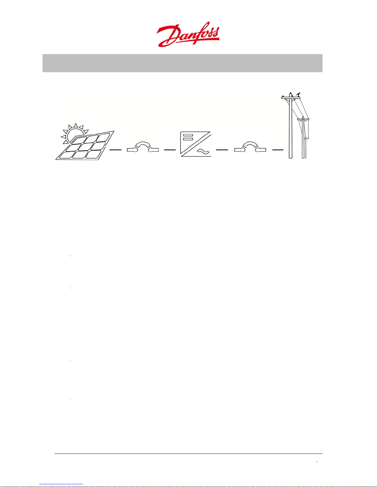
Figure 1.1: PV
fficient singl
e solar array
system overvie
phase grid
tie inverters
on the
In a g
consi
com
DLX
he t
provi
of gr
phot
well
and
easy
Inte
The i
mon
color
a PC
provi
or w
rid-connect
sts of an inv
atible with t
L series
pology of t
es galvanic
at adaptabil
voltaic (PV)
s thin-film
ountry-spec
nd straight
rated Web
verter is eq
hly and year
d LCD scre
r via the Int
es storage
ekly interval
d photovolt
rter, which
he voltage a
e DLX UL se
isolation fro
ity and user
installation.
odules, and
fic requirem
rward insta
erver
ipped with
y basis. All i
n on the fro
rnet. All set
f data with
for thirty y
ic system t
onverts DC
d frequenc
ies consists
the grid th
riendliness,
ifferent con
make it easy
nts. The co
llation and
n integrate
formation is
t of the inve
ings and da
ifteen-minu
ars.
e interface b
ower produ
of the grid.
f an embed
ereby meets
he DLX UL s
figuration o
and afforda
pact and li
aintenance.
web server,
displayed al
rter. The dat
a are saved i
e intervals f
etween the
ed from th
ed high-fre
the strictest
ries is the pe
tions make
le to config
htweight co
which recor
pha-numeri
is also acce
n the integr
r one week,
olar array a
solar array i
uency tran
safety stand
rfect choice
it suitable fo
re for vario
nstruction p
s data on a
ally and in g
ssible either
ted logger,
daily interva
d the grid
to AC pow
former, whi
ards. Becaus
or any
crystalline
s condition
ovide for
daily,
raphs on a
directly fro
hich
ls for one ye
r
h
s
r
Auto
matic Syste
he s
stem is full
gene
ates enoug
ensu
es the highe
the s
lar array sto
6
automatic.
power. Dur
st possible e
ps generatin
he inverter
ng the day t
ergy harve
g power.
tarts up in t
e maximu
t. The invert
e morning
power poin
r goes into
hen the sol
t tracking (
leep mode
U
ser Guide DLX UL
r array
PPT) functio
t dusk whe
series L00410625-
01
u
P
T
c
m
b
S
U
2
d
E
G
r
T
n
t
X
X
X
X
g
U
s
f
r
c
a
o
i
O
w
n
g
e
l
m
U
U
e
V
t
d
v
b
e
u
a
d
r
n
t
p
v
x
n
0
0
0
0
t
s
n
n
o
r
k
u
D
e
s
c
2.
2.1.
his
asse
sym
DLX
the g
Table
Gri
•
IE
ROD
hapter give
bled. A brie
ols appearin
tanda
L inverters a
rid settings
.1: Approved st
Protection
E 1547
CT
an overvie
explanatio
both on th
ds and
re compatib
hosen:
ndards
VER
of the inver
of how to u
inverter an
Appro
e with most
Safety
•
UL 1741
IEW
er with its s
npack and h
in this Use
als
directives an
pplied com
ndle the in
Guide are e
d safety sta
EMC
•
FCC level B
•
IEC/EN 610
•
IEC/EN 610
•
IEC/EN 610
•
IEC/EN 610
onents and
erter safely i
plained.
dards, depe
0-6-2 (immu
0-6-3 (emissi
0-3-2/-12 (ha
0-3-3/-11(flic
how they ar
given, and
ding upon
ity)
n)
monics)
er)
2.2.
2.2.1
2.2.2
Seve
requi
he i
inver
•
DL
•
DL
•
DL
•
DL
•
Ne
•
DC
enera
al variations
rements.
Varia
.
structions g
ers:
2.0 UL
2.9 UL
3.8 UL
4.4 UL
Opti
.
ative or pos
fuses
l Infor
of the DLX
nts
iven in this
ns
tive ground
ation
L are availa
ser Guide ar
d system
le for differe
applicable
nt configura
o the followi
ions and co
ng series of
ntry-specifi
LX UL solar
User G
ide DLX UL series
L00410625-01
7
r
x
n
e
e
P
t
v
o
W
w
d
e
2
b
c
7
g
e
0
v
O
a
e
b
p
e
A
a
A
o
A
n
O
mcha
u
n
n
r
k
V
g
o
b
q
i
s
a
t
t
h
o
e
h
e
y
f
r
d
a
e
a
n
t
p
f
u
t
m
r
a
f
a
r
t
m
e
e
t
f
f
w
a
d
g
h
a
b
,
o
s
j
h
c
e
a
t
0
j
2.2.3
2.3.
•
Wo
•
Fle
•
Mo
•
Int
int
•
MP
•
DC
•
Aut
•
An
•
Re
•
Gr
The
avoi
app
Table
Sym
Key F
.
ld’s highest
ible system
itoring 24/
rnal data lo
rvals for on
T range: 23
oltage rang
omatic ON/
i-islanding p
erse DC pol
und Fault D
arnin
arning sym
hazards to
ar!
.2: Symbols app
ol D
eatures
peak efficie
onfiguratio
ger with sto
year or wee
- 500VDC
e: 220 - 600
FF switchin
rotection
rity protecti
tection and
Sym
ols used in t
eople and e
earing in the Gu
scription
cy for isolat
age capacit
ly intervals
DC
and tempe
n (diodes)
Interruption
ols
his User Gui
uipment. P
ide
d inverters:
of 15 minu
or thirty yea
ature regula
e highlight i
y particula
p to 97.3 %
es intervals
rs
tion
portant in
attention
or one week
formation
hen these
, daily
n how to
ymbols
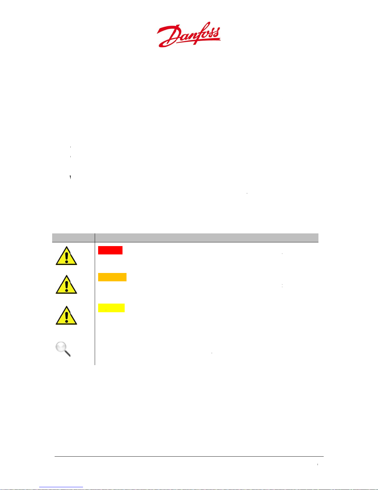
D
NGER:
de
Situat
th to worker
ons where an
and/or the g
immediate h
neral public i
zard could c
not avoided.
use serious in
ury or
W
RNING:
res
ult in the dea
av
ided.
C
UTION:
thr
eat of injury t
ge
eral public.
TICE:
N
da
age of prop
racteristics. T
sit
ation.
Situati
Situ
h or serious i
Situa
rty and equi
tions where
ions where a
at could resu
ns where a n
ere is no “Sa
potentially h
jury of worke
non-immedia
lt in minor or
on-immediat
ment. May b
ety Alert” or a
zardous con
s and/or the
te or potentia
oderate inju
or potential
used to indic
ttention sym
ition exists t
eneral publi
l hazard pres
ries to worker
azard presen
te important
ol present in
at could
if not
nts a lesser
s and/or the
ts a risk to
operational
his
8
U
ser Guide DLX UL
series L00410625-
01
u
1
T
p
e
2
b
l
c
D
Dsw R
m
D U
p
D
m
r
e
Us
n
k
u
e
N
r
h
s
e
d
h
t
g
t
v
s
e
u
a
r
!
t
h
r
t
h
a
s
1
t
h
m
e
2.3.1
2.3.
he
impo
visibl
Table
Sym
Labe
.
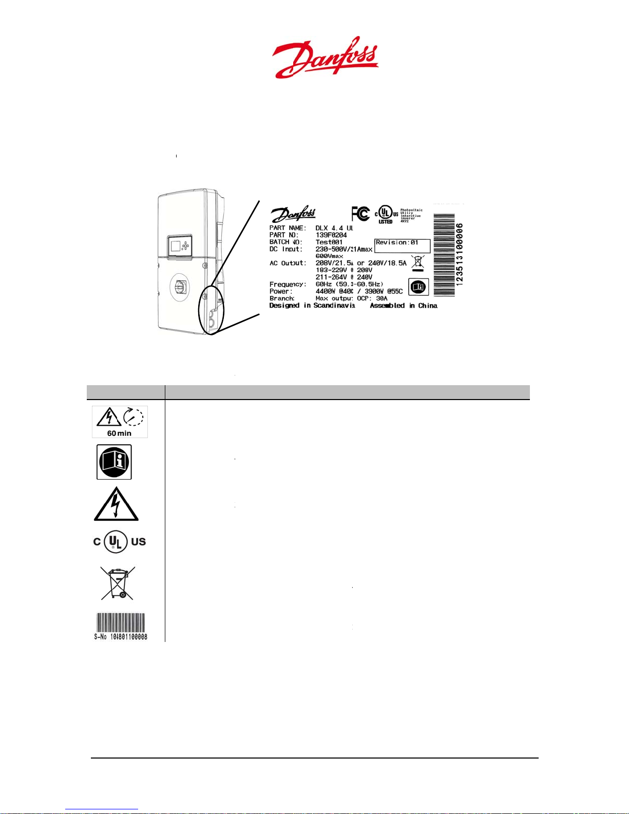
.1. Prod
roduct label
rtant identifi
after install
.3: Symbols app
ol
ing
uct Label
is attached t
ation infor
ation.
earing on the p
escription
o the lower
ation and c
Figure 2.1:
oduct label
ight side of t
aracteristic
Product Label
he inverter
for the inve
ousing. It co
ter, and mu
ntains
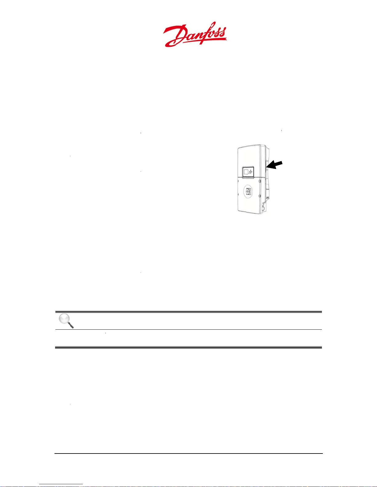
t be clearly
ischarge tim
itch OFF
efer to this
ust be read a
anger: Shoc
L listing: The
rotection req
isposal: Do n
nd recycle th
a
S
– NO: Serial
: High voltag
er Guide: Th
d understoo
hazards – let
product mee
irements.
ot dispose in
m according
umber for in
es may be pr
safety preca
prior to inst
al voltages a
s the UL 1741
eneral waste
o local regula
erter identific
sent inside th
tions and ins
llation
e present
safety, healt
Collect the v
tions
ation
e inverter for
ructions in t
and environ
rious parts s
hour after
is Guide
ental
parately
User G
ide DLX UL series
L00410625-01
9
1
T
P
e
2
m
U
w
y
D
d
e
b
g
t
e
Turn
L
e
e
C
r
k
c
m
p
e
p
a
d
n
n
b
a
C
o
d
s
e
m
t
e
a
e
s
s
e
u
i
.
c
h
T
o
o
g
r
h
e
e
t
T
o
e
g
e
i
r
o
v
u
e
e
o
h
e
t
u
0
e
a
t
2.4.
2.4.1
2.3.
he
conn
Table
Sy
Follo
injur
The
stan
How
distri
.2. PCB
CB labels id
ction area.
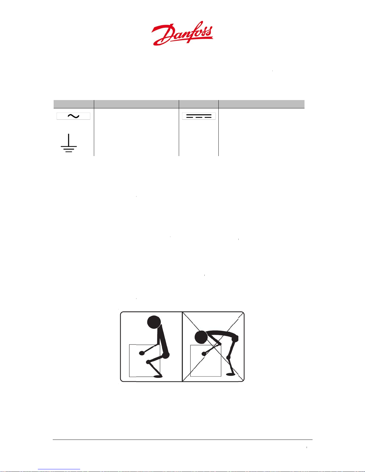
.4: Symbols app
bol D
npac
the instru
and equip
Ship
.
LX UL invert
ards and ap
ver, if any d
utor imme
abels
ntify import
earing on the P
scription
A
: Alternating
rminal.
te
G
ounding: Gr
ing an
tions in this
ent damag
ing Da
r series are
rovals prior
mage to th
iately!
nt informat
B
current
und terminal
Inspe
ection to un
.
age
horoughly c
to shipping.
inverter is f
on about th
Symbol
tion
pack and lift
ecked and
he inverter
und when u
different te
Descr
DC: Di
the inverter
ested in acc
is carefully p
npacking, pl
rminals in th
iption
ect current t
safely and t
rdance wit
acked befor
ease report i
customer
rminal.
prevent
internation
shipping.
to your
l
2.4.2
Liftin
inver
•
Wh
•
Lift
•
10
Liftin
.
and carryi
ers’ weight i
n lifting, be
carefully, ho
the whole
g and C
g the invert
s 49 – 53 lb
d the knee
d the invert
ody as one
rrying t
r must be c
. / 22 - 24 k
Figure 2.2: Co
, and keep t
r close to th
nit to avoid
he Inver
rrectly perf
(depending
rect lifting of th
e back strai
body and l
twisting the
ter
rmed to pre
on model).
inverter
ht.
t the leg m
lower back.
ent back inj
scles do the
U
ser Guide DLX UL
ries, as the
work.
series L00410625-
01
u
r
c
t
m
t
m
The
s
X
u
t
c
T
h
M
v
t
u
e
d
p
e
t
h
h
w
c
g
h
e
h
d
C
t
u
t
e
d
v
e
e
b
e
:
t
o
e
p
s
i
a
r
v
r
e
p
t
n
e
o
e
o
o
n
e
e
w
e
h
e
t
s
s
n
n
a
u
.
e
s
o
r
o
e
g
u
d
t
w
w
i
m
t
p
u
o
d
”
g
•
Car
y the invert
r close to th
body.
2.4.3
Unpa
•
Pla
the
•
Cu
•
Re
the
•
Bot
bet
the
•
Re
out
•
•
Sto
reu
After
Unpa
.
ck the invert
e the box in
packaging.
the seal, an
ove the up
envelope wi
h sides of th
er grip on t
box using t
ove the lo
the inverter
bag with ac
e all the ori
e.
unpacking t
cking
er as follows
position, wi
open the b
er part of th
th the extra
inverter ca
e inverter. L
e “handles”
er section of
mounting b
essories is a
inal packing
e inverter, c
h the top cl
x.
foam packi
roduct labe
e are narro
ft the invert
s illustrated
the foam pa
acket.
ttached to t
material for
heck that all
arly visible a
ng material
l.
ed in order t
r carefully o
in Figure 2.3
ckaging and
e bracket.
possible lat
component
nd accordin
nd take out
o get a
ut of
take
r
Fig
are include
to the arro
the Installat
re 2.3: “Handles
and unda
markings
on Guide an
aged.
n
2.4.4
•
DL
•
Mo
•
Ins
•
Ac
2.4.5
he
•
NE
•
Pro
wa
•
Be
Scop
.
UL single p
nting brack
allation Gui
essories: gro
NOTI
Condui
and m
Inver
.
ousing of th
A 3R for in
ide a degre
er, hose-dir
ndamaged
of Deli
ase inverte
t
e
unding stra
E
s, fittings a
st be provid
er Encl
DLX UL inv
oor or outd
of protecti
cted water a
y the exter
ery
, bracket scr
d bonding s
d by the sy
sure
rter series i
or use.
n from falli
nd corrosion
al formatio
ws, extra pr
raps are not
tem installe
designed t
g dirt, rain, s
.
of ice on th
duct label
part of the s
.
:
leet, snow,
housing.
andard sco
indblown d
e of supply,
st, splashin
User G
ide DLX UL series
L00410625-01
1
1
5
5
T
r
u
r
o
T
o
d
t
h
r
t
o
5
r
p
o
o
z
e
a
e
u
o
s
c
o
e
o
s
f
w
n
t
C
r
u
e
3
9
d
p
s
wsw
o
e
a
e
a
m
m
m
d
v
w
h
o
o
o
e
b
c
w
0
e
m
c
o
i
2.4.
2.4.
he f
.1. Mec
Figu
.2. Fron
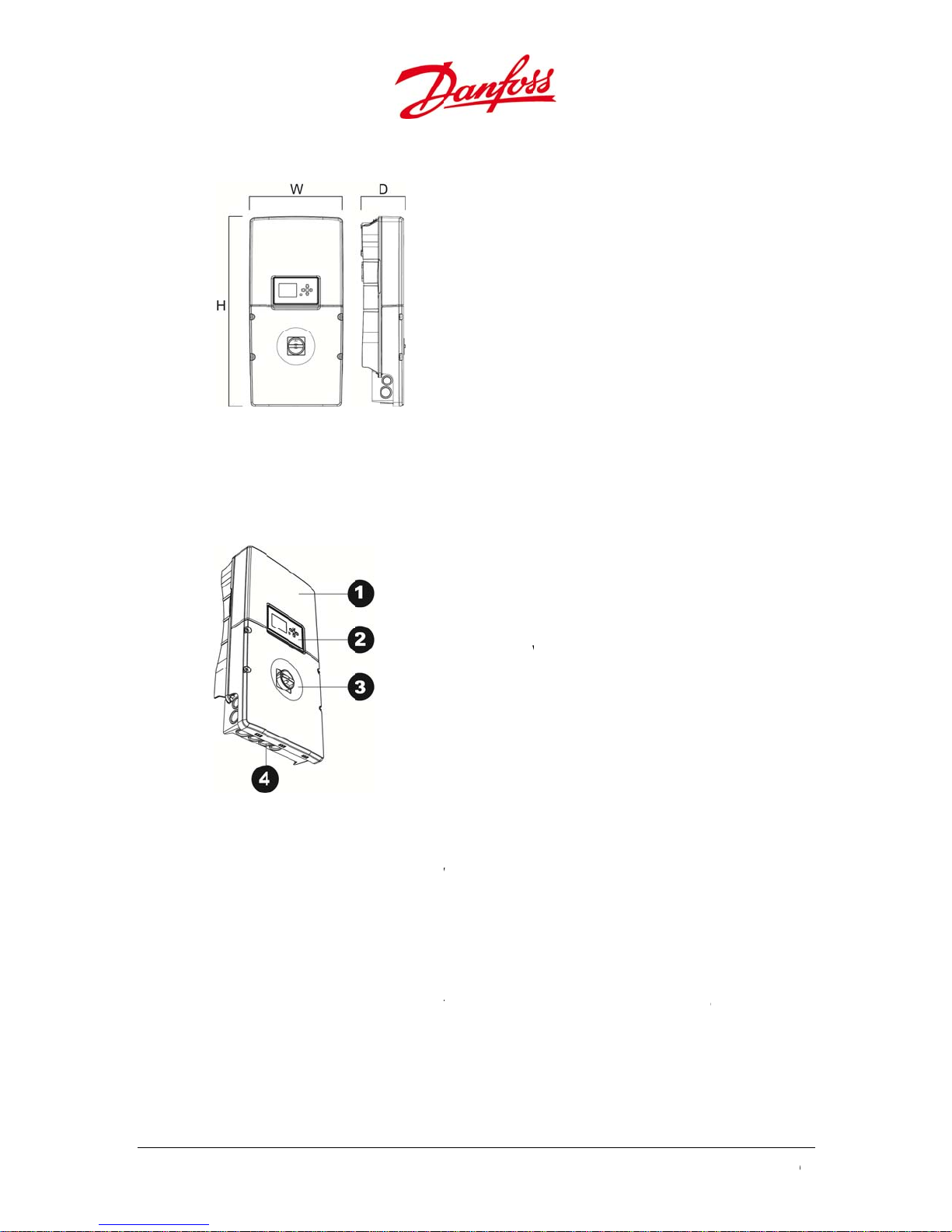
ont surface
anical Di
2.4: Mechanic
Covers
f the invert
mension
l dimensions
r consists of
H: 28.
W:13.
D: 6.2 i
an upper an
1. U
2. Di
3. Lo
4. H
inches / 720
inches / 353
nches / 158
a lower co
per cover
play
er cover wit
itch
le covers (Kn
m
m
m
er.
DC disconn
ckouts)
ct
Figure 2.
The
pper cover
cove
by unautho
The l
instal
2.4.6
calle
easy
12
wer cover
ler for electri
.
he l
wer cover p
the Stringb
o de-energi
Rem
: Inverter struct
may be rem
ized person
rotects the
cal connecti
ving th
rotects the c
x. The lowe
e the DC ter
re
ved by Dan
voids the
ustomer co
n and main
Lower
nnection a
r cover is eq
minals on th
oss authoriz
arranty!
nection are
enance.
over
ea in the inv
ipped with
inverter.
d persons o
, and may b
rter and als
DC switch
nly. Remova
e removed
the inbuilt
n the front,
U
ser Guide DLX UL
l of the upp
y the syste
ombiner b
hich make
series L00410625-
r
x
t
01
u
Tur
m
o
s
N
T
C
G
F
n
u
r
w
T
e
o
n
g
b
a
n
t
F
c
w
n
r
e
h
p
D
c
e
h
f
t
t
r
m
n
h
x
o
o
f
t
f
c
o
t
p
t
n
o
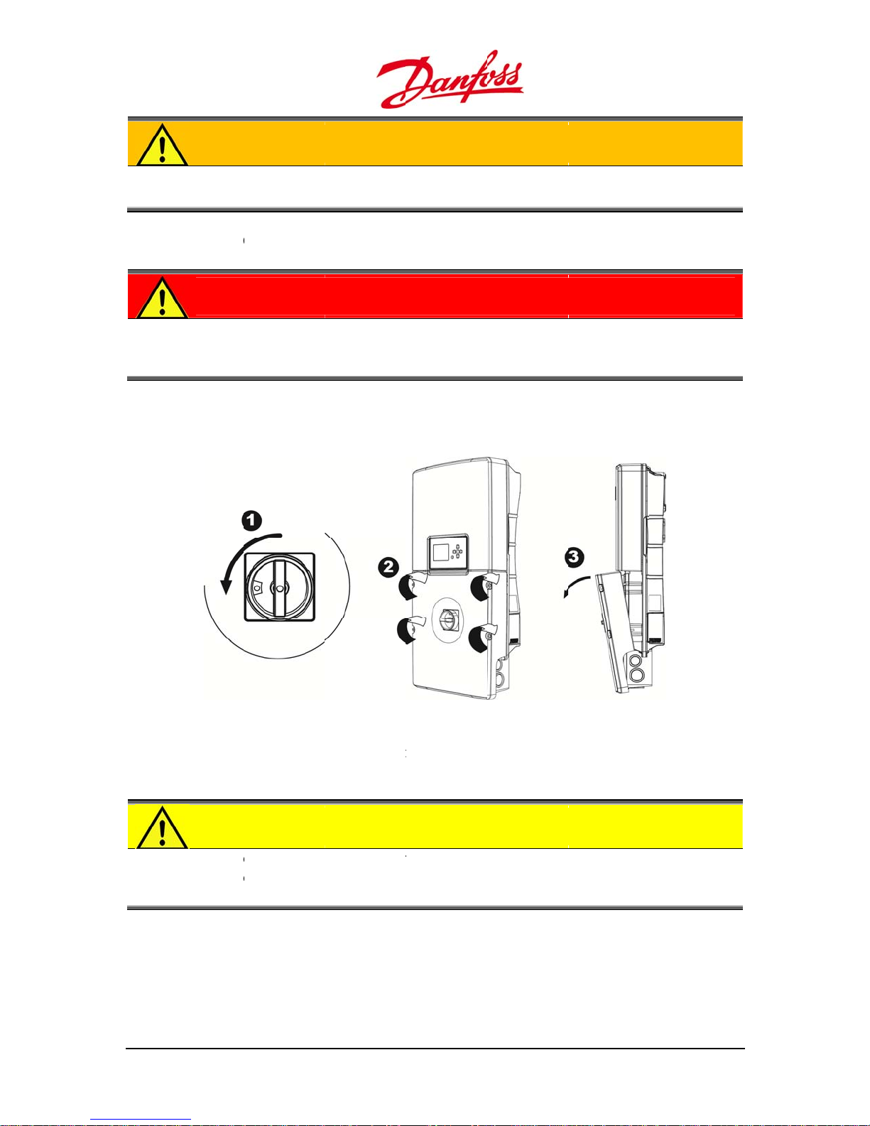
1.
2. Re
3. An
WAR
he inv
only be
n OFF the A
DAN
Always
DC OF
to the i
ove the fo
gle the cove
ING
erter is char
performed
circuit bre
ER
disconnect t
, but before
verter whe
r screws on
outwards, a
ed with hig
y qualified
ker and the
he PV array
removing th
exposed to
he front wit
nd take it of
voltages, a
ersons.
C - switch.
ables from t
covers, as t
sunlight.
a 4 mm he
carefully.
d removal o
e inverter a
he PV array
key.
f the lower c
ter turning
an supply u
ver may
he AC and
to 600 VDC
4. St
5. Fa
User G
re the lower
ten the scre
CAU
Never r
lower c
electro
ide DLX UL series
cover and s
s on the lo
ION
move the i
ver during
ic compon
L00410625-01
igure 2.6: Remo
rews safely
er cover wi
verter lowe
ain or in da
nts.
ving the lower c
o avoid loss
h a torque o
cover in we
p condition
ver
r damage.
0.74 ft-lbf /
conditions!
s can damag
1.0 Nm.
Removal of
e sensitive i
he inverter
ternal
1
3
S
T
c
s
w
G
D
n
a
e
The
n
T
a
e
e
t
n
C
T
e
b
u
N
T
u
o
o
G
w
r
g
c
s
E
o
a
h
r
t
i
o
a
a
c
g
u
e
D
e
u
T
t
t
c
t
0
u
t
o
u
o
s
e
i
S
e
y
p
n
H
t
c
g
e
s
c
u
s
e
o
n
v
i
r
L
a
l
d
p
e
n
e
e
n
0
r
d
e
3.
3.1.
his
serie
instal
lation. Failur
the
The
main
tenance mu
feder
al electrical r
the i
AFE
hapter cont
safely. Thes
arranty.
enera
LX UL inver
structions i
Y PR
ins instructi
safety prec
to follow t
l Prepa
er series con
st be perfor
egulations A
this User Gu
CAU
ns on how
utions mus
e safety pre
ations
ain no user-
med by qua
NSI/NFPA 7
de.
ION
o install, op
be read tho
autions ma
serviceable
lified perso
NEC and OS
rate and ma
roughly and
result in inj
arts, and in
s, who hav
HA, and foll
intain the D
understood
ry or death
tallation an
knowledge
w such regu
X UL inverte
prior to
nd may voi
d
of state and
ations, and
3.1.1
Cont
conn
•
Rea
•
co
NOTI
he saf
to be a
Conn
.
ct the local
cting to the
WAR
o ens
to pers
be perf
DAN
Never
breake
dischar
d the instru
inverter mu
nected to th
E
ty precauti
le to install
ections
tility comp
grid.
ING
re safe and
ns or dama
rmed by q
ER
ork with en
(s) and the
ed and saf
tions and ca
t be connec
is circuit.
ns and instr
nd operate
ny for interc
orrect electr
e to the eq
alified pers
rgized port
C switch mu
to work on.
tions on th
ted to a ded
ctions in thi
he inverter
nnection a
ical connecti
ipment the
ns.
! Prior to the
st be turned
PV module
cated AC cir
s User Guide
orrectly.
reements a
on of the in
lectrical wir
electrical co
OFF to ensu
prior to the
uit. No othe
must be rea
d power ap
erter and pr
ng and con
nnection, th
re that the t
electrical co
r devices are
thoroughly
roval befor
vent injury
ection must
AC circuit
rminals are
nection.
to be
14
U
ser Guide DLX UL
series L00410625-
01
u
T
n
The• To a
h
eope
o
i
t
a
C
X
e
s
T
h
d
v
v
C
T
e
u
v
h
m
t
a
t
t
a
C
n
n
r
a
w
t
e
s
e
e
t
m
c
a
o
h
d
n
n
d
t
c
o
t
n
b
t
o
e
h
u
e
u
e
e
a
t
c
z
t
n
z
c
e
b
e
s
e
e
e
u
t
w
S
d
o
e
e
z
a
t
T
a
d
u
t
w
q
u
o
T
e
s
o
g
g
e
n
t
c
d
n
t
r
n
u
e
C
3.1.2
he i
•
tec
Oper
.
verter must
NOTI
The DL
design
electric
inverter mu
void damag
nical specifi
CAU
Keep t
PV mo
the PV
the PV
tion
only be ope
E
UL series is
d purpose,
ity to feed in
t be operat
e to the inve
cations.
ION
e voltage an
ules is inver
oltage incr
oltage decr
ated in acco
grid intera
hich is to c
o the grid.
d without a
rter, it must
d current wi
ely proporti
ases from th
ases from t
rdance with
tive inverter
nvert PV-ge
y unauthori
e used with
hin the spe
nal to the t
product la
e product la
the instructi
and must b
erated DC
ed modific
in the opera
ified limits!
mperature;
el rating an
bel rating.
ns in this U
used exclus
lectricity int
tions.
ional limits
he voltage
t lower tem
at higher t
er Guide.
ively for its
AC
iven in the
enerated by
peratures
mperatures
•
Mis
int
•
Ign
ma
3.1.3
Prior
and t
NOTI
he op
maxim
of the s
temper
use of the in
rfere with t
rating and
ring the ins
ntenance m
Main
.
o service an
he DC sides
NOTI
Accessi
must o
compo
E
n circuit vol
m PV syste
eries-conne
ature.
erter may d
e operation
aintaining t
ructions an
y void the i
enance
d maintena
nd be fully
E
ng the inver
ly be opene
ents.
age, VOC, m
voltage is
ted PV mod
mage the d
f the invert
e inverter.
guidelines i
verter warr
ce, the inver
ischarged.
er upper se
d by authori
st never exc
qual to the
les, correct
vice or oth
r, or may ev
n this User G
nty.
er must al
Refer to 8.1.
tion voids th
ed persons
ed 600VDC
um of the ra
d for the lo
r electrical e
n cause inj
ide and not
ays be disc
witch-OFF.
e warranty.
ue to dang
nder any co
ed open-cir
est expecte
quipment a
ry or death
performing
nnected o
he inverter
r of damag
ditions. The
uit voltage,
ambient
d can
o persons
egular
both the A
pper cover
to internal
User G
ide DLX UL series
L00410625-01
1
5
The
t
t
g
f
a
S
3.2.
c
s
s
F
w
d
s
n
n
e
w
n
i
T
g
n
m
s
e
o
b
n
w
o
s
c
a
a
m
v
t
n
o
k
m
d
a
m
e
d
v
n
d
i
a
n
e
d
o
o
n
m
5
1
9
9
n
e
n
n
m
e
e
e
u
0
r
o
d
•
inverter lo
ins
allation and
unauthorize
•
No
dis
ributor in ca
•
Re
ular mainte
(re
•
A s
Obse
rve the follo
able site. Thi
a suit
r to 8.2. Reg
fety compo
ite Pr
er cover mu
maintenanc
modificati
e of failure.
ance must
ular System I
ent must al
parati
ing precaut
is crucial to
t only be ta
or repairs.
ns may be
e performe
spections).
ays be repl
ns
ions when
maintain th
en off by qu
ade to the i
to maximiz
ced by the s
ounting an
efficiency
lified perso
verter. Cont
the life exp
ame type an
installing th
f the inverte
s during th
act the syste
ctancy of th
d rating.
e DLX UL inv
r!
electrical
m installer o
e inverter
rter series
n
3.2.1
Suffi
up in
•
Ob
Mou
.
ient ventilat
ide the inve
CAU
Insuffic
space a
coolin
erve the mi
ting Lo
on and low
rter, which c
ION
ent cooling
round the in
and efficien
imum dista
ation
mbient tem
n result in p
ay lead to
erter and u
operation.
ces specifie
perature are
ower losses.
egradation
blocked ve
below to
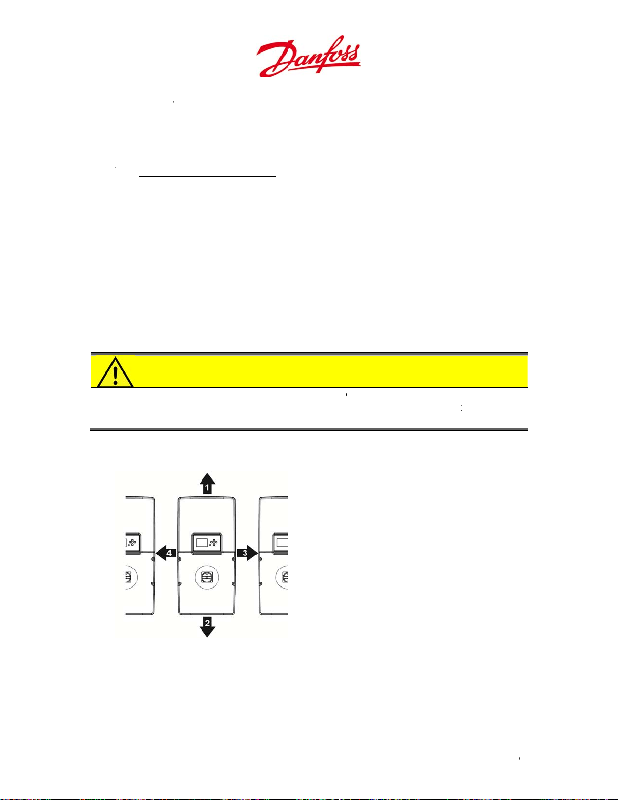
1. 1
2. 1
3. 5.
4. 5.
needed to p
of performa
tilation ope
aintain opti
.75 inches / 4
.81 inches / 3
91 inches / 15
91 inches / 15
revent temp
ce! Ensure s
ings for opt
al cooling:
00 mm
00 mm
0 mm
0 mm
rature buil
fficient air
imum
-
igure 3.1: Mini
16
um distances f
r optimum cool
ng
U
ser Guide DLX UL
series L00410625-
01
u
The
ecom
e
d
T
n
s
e
m
e
n
N
o
s
c
m
u
l
o
f
u
N
e
s
o
m
e
n
g
C
e
a
d
q
T
T
n
9
c
e
s
-
o
m
m
d
m
p
u
/
a
t
r
o
y
a
t
e
m
w
e
b
e
o
v
r
m
e
l
s
n
y
4
t
e
m
e
4
o
l
h
n
5
%
r
e
p
2
n
i
o
E
v
u
°
o
u
a
f
c
p
e
e
c
•
•
Ke
•
It is
the
•
Th
rea
3.2.2
he i
and t
•
Ens
du
•
Ens
•
Th
te
int
•
No
WAR
The m
temper
inverter mu
p the lower
ponents.
not recom
inverter.
display sho
ily accessib
Envir
.
stallation o
he OSHA reg
WAR
Protect
the inv
period
ure a longer
ty, dry and c
ure a non-fla
ambient te
perature ris
rnal compo
-condensin
ING
unting surfa
ature (194°F
t be mount
over closed
ended to in
ld be at eye
e.
nment
the inverter
lations.
ING
the inverter
rter heat sin
of high perf
life and opti
ol environ
mmable an
perature sh
s above 104
ents.
relative hu
e must be s
90°C) of the
d in a vertic
when moun
tall the inve
level, the pr
must compl
from flamm
k can reach
rmance op
um perfor
ent
non-explosi
ould be bet
°F/+40°C th
idity must
itable for th
inverter.
l position.
ing the inve
ters in living
duct label
with local r
ble and exp
emperature
ration.
ance of the
ve environm
een -13°F a
inverter ma
e between
e weight (4
rter to avoid
areas due t
ust be visib
gulations, t
osive enviro
as high as 1
inverter by i
ent to avoid
d 149 °F/-2
start to red
% and 99
-49 lbs/20-2
damage to i
possible no
e and the c
e National
nments to a
94°F/90°C d
stalling it in
fire.
°C and +55
uce power t
.
kg) and
ternal
se levels of
nnection ar
lectrical Cod
oid fire, as
ring long
a clean, non
C. If the
protect
a
-
NOTI
Avoid
losses,
reduce
screen
CAU
User G
he inv
come i
194°F/
ide DLX UL series
E
xposing the
s direct sunl
power out
uality.
ION
erter should
contact wit
0°C.
L00410625-01
inverter to d
ight causes i
ut. Also, dir
be installed
h the rear in
irect sunligh
ncreased int
ct sunlight
n a location
erter surfac
! Direct sunl
rnal tempe
ay cause d
where peo
, due to tem
ight may ca
ature that c
gradation o
le cannot ac
peratures u
se yield
n lead to
the LCD
identally
to
1
7
Thesno
e
R
3.3.
p
p
o
t
n• Thehav
p
c
e
o
f
u
d
n
e
t
e
C
e
a
a
o
v
b
c
d
p
t
c
e
p
f
e
u
d
n
t
m
E
n
t
m
d
t
m
t
P
t
e
e
t
m
p
t
d
e
-
n
a
k
l
e
o
s
h
V
i
a
p
n
n
t
e
d
e
e
t
u
u
e
m
s
f
n
e
e
h
a
e
e
o
e
m
a
t
i
d
n
d
0
e
e
t
t
•
•
Inv
Com
equi
inverter is s
w and rain,
rter locatio
equir
liance with
ment requir
itable for o
ust and san
should be i
d Safe
he local and
ments.
tdoor opera
.
close proxi
y Equi
federal elec
ion, but sho
ity to the P
ment
rical regulat
uld be shelt
arrays to
ons is requir
red from dir
inimize DC l
ed to satisfy
ct sunlight,
sses.
the safety
3.3.1
Disc
durin
from
main
•
Bot
co
•
Eac
be
3.3.2
NOTI
Safety
compli
adequ
Disc
.
nnection de
g operation.
power surge
enance and
h AC circuit
ductor to fa
disconnect
e an interru
h disconnec
ermanently
Over
.
E
quipment
nce with N
te.
nnectio
ices, switch
They protec
s and syste
repairs.
reaker(s) an
ilitate maint
evices mus
t rating suffi
ion device
marked for
urrent
ust be provi
to ensure t
Devic
es or circuit
the current
malfunctio
DC switch
enance wor
conform to
cient for the
ust be readi
heir purpos
rotecti
ed and inst
he required
s
breakers, e
carrying co
s, and help
re recomm
and repairs
the local an
voltage and
y accessible
.
n Devic
lled by the
rotection o
able a shutductors and
o shut dow
nded on ev
of the invert
federal elec
current avail
and totally e
s
ystem instal
the PV syst
off from the
other syste
the inverter
ry current-c
r.
trical regula
able in the c
nclosed. All
ler in
m is
power sourc
componen
safely for
rrying
ions, and
rcuit.
evices mus
s
Over
urrent prot
prev
nt overheati
•
An
vercurrent
•
If a
use blows o
rep
lacing or res
18
ction device
ng as a resul
rotection d
r a circuit br
tting it.
, fuses or ci
of overload
vice is requi
aker trips, t
rcuit break
, short circui
red on each
e cause sho
rs, protect t
or ground f
ngrounded
ld always b
e circuit co
ult.
conductor.
determine
U
ser Guide DLX UL
ductors and
before
series L00410625-
01
u
2
The
n
u
h
The
2
a
e
Theman
t
3
v
2
The
d
u
c
d
a
u
n
e
u
f
t
t
e
U
f
r
h
C
s
e
r
O
e
T
T
u
p
a
o
i
l
f
x
V
t
u
n
p
e
A
5
0
0
t
2
r
v
n
r
y
f
h
g
e
e
c
f
e
o
d
x
A
q
u
e
e
F
p
s
n
m
e
a
p
m
e
h
o
t
e
a
o
.
t
r
s
r
d
e
r
o
n
m
n
x
o
T
o
d
P
m
e
h
e
n
y
o
3.3.
•
or i
eq
•
If t
7.2.
•
3.3.
•
DC
loc
ind
•
•
DC
sys
Table
In
.1. Gro
GFDI prote
the PV con
ipped with
e ground fa
Table of Eve
rating of th
.2. DC F
uses protec
ted in the S
pendently.
rating of th
ufacturer,
uses are no
em installer.
.1: DC current c
erter Type
DLX 2.0 UL
DLX 2.9 UL
DLX 3.8 UL
DLX 4.4 UL
nd Fault
ts the negat
uctors. It is
finger-safe
lt current e
ts).
GFDI is 600
ses
the conduc
ringbox, eq
DC fuses sh
L requireme
mally not a
aracteristics an
Max
Curr
9.5
13.
18.
21.
Protectio
ve/positive
ocated in th
use holder.
ceeds 1A th
and 1A.
DC
ors from ba
ipped with
ould be as p
ts and NEC,
art of the sc
d recommende
DC
nt
A
A
A
n (GFDI)
rounded str
lower com
GFDI open
k feed curre
inger-safe fu
r the recom
with a maxi
pe of deliv
fuse ratings
1
PV String
Fuses
15A
22A
29A
33A
ings from gr
artment of
and the inv
nts from par
se holders t
mendations
um of 40 A
ry, and mus
2x PV St
Fuse
8A
11A
15A
17A
und faults i
he Stringbo
rter shuts d
llel strings.
disconnect
of the PV m
be provide
ing 3x
the PV arra
and is
wn (Refer t
hey are
each fuse
dule
by the
V String
Fuses
5A
8A
10A
11A
3.3.
•
an
•
AC
User G
NOTI
Overcu
which i
string c
modul
.3. AC O
AC Overcur
the grid.
CD must b
CAU
o red
circuit
Nation
3.2 bel
ide DLX UL series
E
rent protec
equal to 1.
onductors o
product lab
ercurre
ent Detecto
provided b
ION
ce the risk o
rovided wit
l Electrical C
w
L00410625-01
ion is not re
5 x ISC,, from
the maxim
el.
t Protect
(OCD) prot
the system
fire, the inv
branch circ
ode, ANSI/N
uired for PV
all sources c
m overcurre
ion
cts the sup
installer.
rter AC ter
uit overcurr
PA 70, and
strings whe
nnot excee
nt device siz
ly conducto
inals must
nt protectio
aving maxi
e the maxi
the ampaci
specified o
s between t
nly be conn
in accorda
um ratings
um current,
ty of the PV
n the PV
e inverter
cted to a
ce with the
as per Table
1
9
3
n
v
U
D
g
s
e
g
o
edev
E
h
e
e
e
a
s
u
O
q
i
g
t
d
t
d
t
g
p
p
s
o
e
r
v
u
u
e
n
r
A
s
2
e
M
h
e
d
a
h
C
e
V
e
d
e
e
p
O
r
o
g
o
X
0
h
s
e
Table
I
.2: AC current c
verter Type
DLX 2.0 UL
DLX 2.9 UL
DLX 3.8 UL
DLX 4.4 UL
aracteristics an
Max A
208VAC
10.0A
14.0A
18.5A
21.5A
fuse rating
C Current
240V
AC
8.5A
12.0A
16.0A
18.5A
208V
15A
20A
25A
30A
AC Fu
AC
es
40V
15A
15A
20A
25A
Tripping
haracteristic
AC
B or C
Type
s
Double
Pole
3.3.3
Over
DLX
the
volta
•
PV
DC
•
Wh
sur
to
•
Ref
•
IEE
des
Surg
.
oltage prot
L series are
C source cur
e surges to
ystems inst
and AC side
n the cond
e arrester.
btain the re
r to NEC gu
ices.
provides a
igned for ca
Protec
ction is use
quipped wi
rent and the
round.
lled in an o
, as they can
ctors are ex
ne or more
uired level
delines for s
ood base fo
egory B: 100
ion
to prevent
h Temperat
AC output c
en or expos
act as lightn
osed to tra
urge arreste
f protection
lecting app
selecting k
kA – 150 kA
oltage surg
re protected
rrent, whic
d environm
ing rods.
sients, their
rs are neede
.
opriate kA r
ratings of t
per phase.
s through s
etal Oxide
diverts the
nt need ad
behavior lim
in installati
tings for ov
e surge arr
nsitive equi
aristors (TM
xcessive cu
ed protecti
its the effect
ons with lon
rvoltage pr
ster: The DL
ment. The
V) on both
rent from
n on both t
iveness of a
conductor
tection
UL series ar
e
20
U
ser Guide DLX UL
series L00410625-
01
u
4.
T
c
d
M
T
m
n
w
The• The
u
f
t
The
o
r
t
s
G
w
m
C
f
t
n
N
o
B
e
T
p
e
s
r
M
d
I
e
e
n
n
u
s
p
l
s
n
i
u
e
a
o
v
i
i
s
n
.
r
o
m
e
c
s
a
c
t
T
o
y
n
e
r
v
e
n
s
m
4
t
c
t
b
t
o
m
e
n
h
s
s
e
o
r
u
e
y
e
e
I
NSTA
his
and
quali
hapter desc
etails impor
fied person
LLAT
ibes how to
ant issues r
who follow
ON
install the in
lated to the
the installat
erter correc
nstallation.
on instructi
ly, both me
he informa
ns as descri
hanically an
tion is inten
ed in this U
d electricall
ded for
er Guide.
,
4.1.
he
dime
DAN
Never
the ter
NOTI
The Sa
installa
echa
ounting sur
sions and h
WAR
Followi
lethal c
ER
ork with en
inals disco
E
ety Precautio
ion proced
ical In
face and the
ousing tem
ING
ng the instal
nsequence
rgized port
nected.
s (refer to 3
res must be
tallati
mounting
erature (Ref
ation instru
.
! All work on
Safety Preca
ead carefull
n
ethod must
r to 10. Tech
tions will pr
the inverter
utions) and t
prior to ins
be suitable f
ical Data).
vent poor p
must be per
he following
allation.
r the invert
erformance
formed with
detailed
r’s weight,
r possible
4.1.1
Depe
the
of fas
•
•
Mo
(Re
ins
•
flo
User G
Wall
.
nding on th
all bracket.
teners to su
bracket is d
inverter mu
nt the inve
er to 3.2.1.
alled.
recommen
r level.
ide DLX UL series
racket
mounting s
he system i
port the we
signed to s
t be mount
ter in compli
ounting Loc
ed height f
L00410625-01
urface, differ
staller is re
ght of the in
pport 176.4
d in a vertic
ance with th
tion). This is
r the conne
ent mountin
ponsible fo
erter on th
lbs. / 80 kg.
l orientatio
e minimum
especially i
tion area is
g methods
selecting th
mounting s
!
pacing to e
portant wit
0 - 55 inche
ay be requi
e correct typ
urface.
sure optim
several inv
/1000-1400
ed to secur
e and numb
m cooling
rters
mm above
r
2
1
m
T
b
m
s
a
s
s
4
c
n
g
c
p
t
w
i
k
g
b
p
v
r
a
d
a
e
a
c
n
0
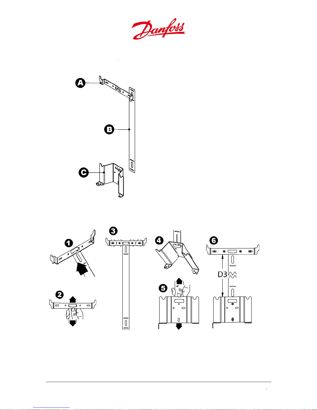
Asse
he
Asse
bling
racket consi
Figure
ble the bra
ts of three
.1: Wall bracke
ket as follo
arts:
components
s:
erter Bracket
A. In
B. Sp
acer (Optiona
ingbox brack
C. St
l)
t
emble the i
1. As
br
cket openin
2. Fa
ten the spa
22
verter brac
.
er by pullin
F
gure 4.2: Assem
et with the s
it over the s
ling the wall br
acer by gui
lit until it is f
cket
ing the spa
stened.
er into the i
U
ser Guide DLX UL
verter
series L00410625-
01
u
abrabra
r
sope
s
e
3
s
The
T
d
m
w
i
t
c
t
n
e
w
D
n
s
t
c
g
e
e
b
e
e
n
e
e
e
a
s
s
s
e
c
u
a
u
f
6
e
e
o
d
a
b
r
6
–
e
e
½
s
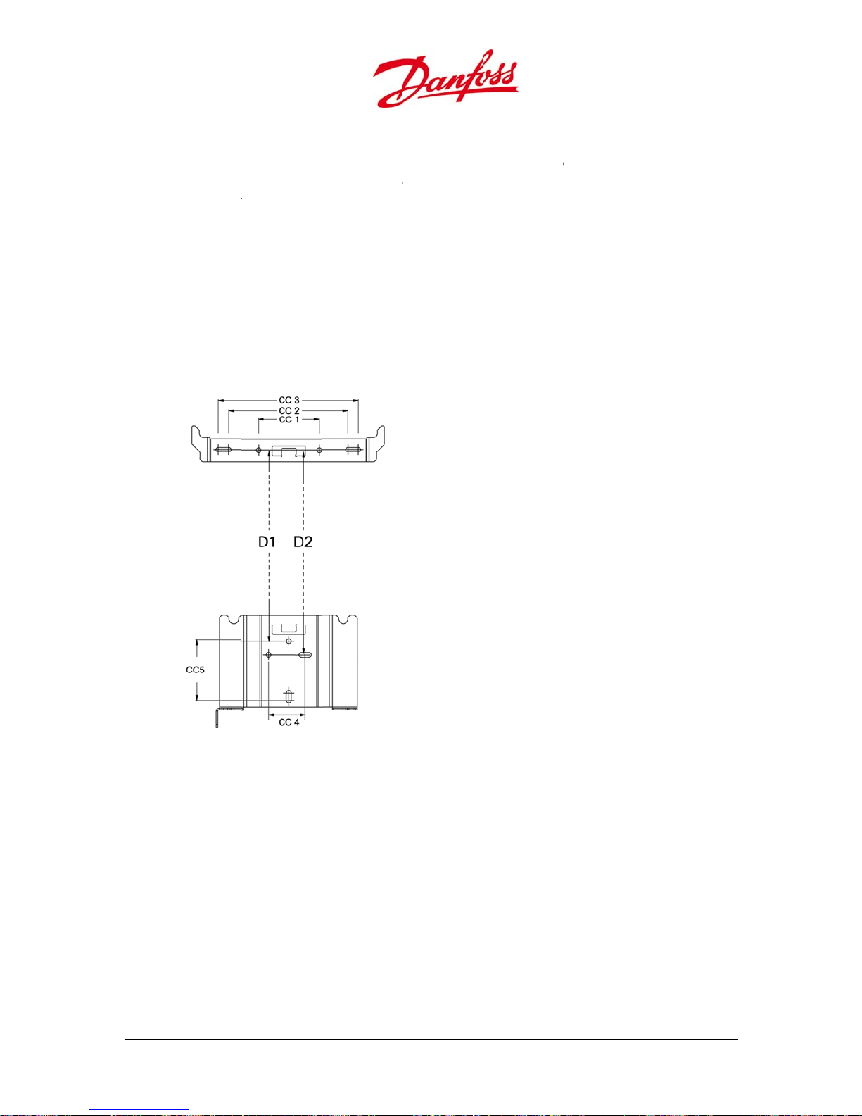
3. M
co
4. As
5. Fa
6. Th
15
Fa
he
/
rk the moun
cket as a te
cket to the
rect dimens
emble the S
ning.
ten the spa
correct dis
” (+ 45/64”).
2
ten the Stri
holes in th
istances bet
ting holes o
plate to en
all with min
on of the scr
ringbox bra
er by pullin
ance betwe
gbox brack
Stringbox
een the scr
the mounti
ure that the
imum 2 fast
ews. The hol
ket and the
it over the s
n the invert
t to the wall
racket have
ws:
g surface u
bracket is co
ners. The in
s in the bra
spacer by g
lit until it is f
r bracket an
with minim
diameter o
CC1:
CC2:
CC3:
CC4:
CC5:
D1:
D2: 1
ing a spirit l
rrectly level
taller is resp
ket have a
iding the sp
stened.
d the String
m 2 fastene
½ inch.
3”
6”
7”
2”
3”
1
/
” (+ 45/64”
164
7” (+ 45/64” – 0
vel and the
d. Fasten th
onsible for s
iameter of
acer into the
ox bracket i
s.
0”)
”)
inverter
inverter
lecting the
inch.
bracket
: D3 = 14
Figure 4.3:
istances betwe
User G
ide DLX UL series
L00410625-01
n the fastener
2
3
cpin
tlow
s
m
C
M
ein
e
hsp
h
n
h
t
e
k
b
C
t
t
n
e
e
e
e
u
h
d
e
e
r
a
o
C
e
h
h
g
T
p
e
s
c
e
e
o
o
v
e
R
r
w
a
t
e
.
r
h
c
e
e
e
m
u
n
d
g
n
e
a
i
h
b
k
7
t
t
t
m
0
t
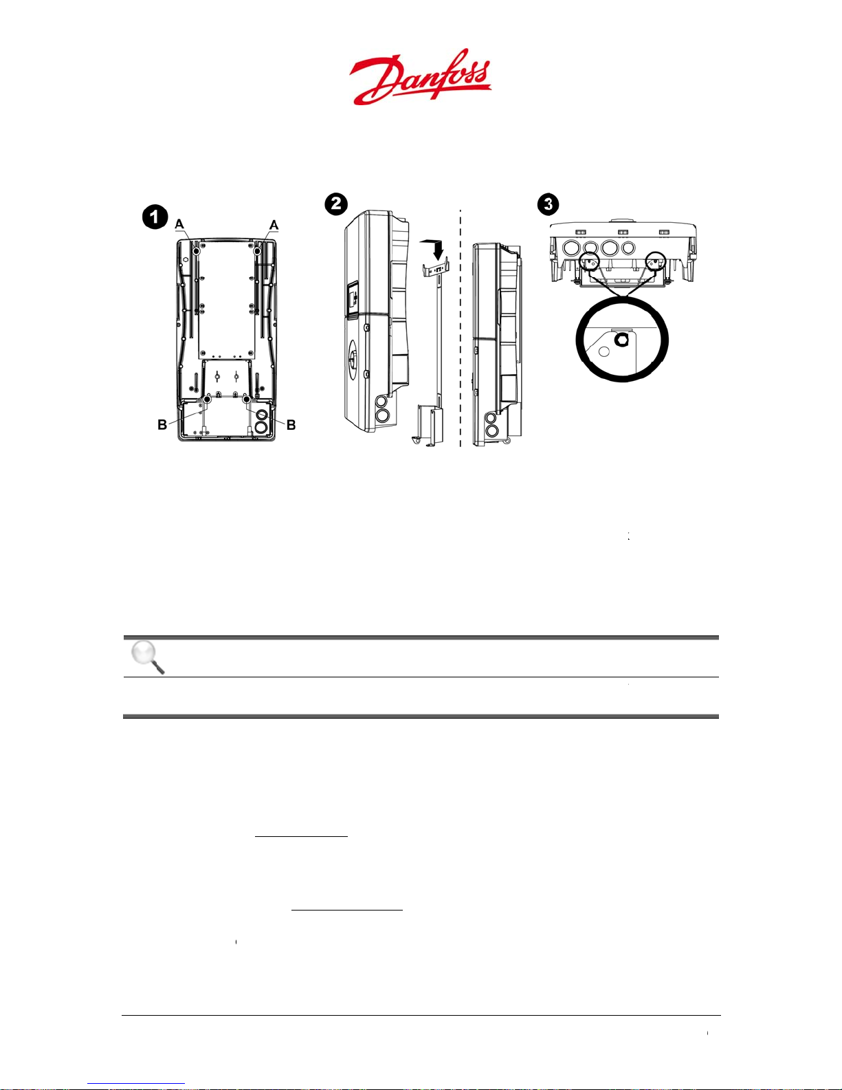
4.1.2
Attac
1. Lo
2. Lif
3. En
scr
N
Inver
.
h the invert
ate the hoo
taps on the
the inverter
er taps into
ure that the
ews on the
.
er
r to the mou
Fig
s for the car
Stringbox (B
and guide t
the slots an
inverter is s
ottom of th
nting brack
re 4.4: Fasten th
rier slots (A)
).
e upper ho
slide the in
curely align
Stringbox.
t as follows:
inverter to the
n the uppe
ks into the s
erter onto t
d in the bra
ecommend
bracket
back of the
lots on the i
e bracket.
ket rails, an
d tightenin
inverter and
verter brac
fasten the i
torque is 0.
the locating
et. Align the
nverter with
74 ft-lbf / 1.0
2
4.2.
24
t
A
r
C
C
E
t
ll electrical i
NOTI
Check
electric
hecks
ake sure tha
rminals are i
verter. Refer
gulations.
eck that th
ecifications.
eck that th
sure that th
at they hav
E
hat the inve
l wiring.
Prior t
both the A
n a discharg
to 8.1. Switc
stallations s
PV and the
Refer to 10.
inverter is
conductor
the correct
ter is proper
Electri
circuit brea
d state to p
-OFF.
all comply
rid specific
echnical Da
roperly fast
are listed fo
olor coding
ly fastened a
cal Inst
ker(s) and th
event shock
ith the curr
tions are co
a.
ned and sec
r PV applicat
nd secured t
allatio
DC switch
hazards dur
nt local and
patible wit
red to the
ions and the
o the bracke
re OFF and
ng the instal
federal elec
the inverte
racket.
site environ
U
ser Guide DLX UL
prior to the
hat the
lation of the
rical
r
ent, and
series L00410625-
01
u
nre
E
4.3.
e
n
T
v
m
n
q
e
c
e
C
T
c
c
u
s
s
s
r
T
T
n
e
e
n
s
e
a
F
e
c
o
e
y
s
t
o
i
b
a
f
n
c
t
z
y
a
t
e
d
n
v
o
r
m
r
d
a
e
r
i
.
r
v
o
e
l
e
h
d
.
s
E
sure that th
gulations in
lectric
electrical i
force at the i
al Insta
stallation c
nstallation s
llation
mplies with
te.
he local an
national ele
ctrical
Corr
the e
ct electrical
tire PV syst
NOTI
he ele
with lo
User G
onnection i
m.
E
trical conn
al and feder
ide.
critical for a
ctions must
l electrical r
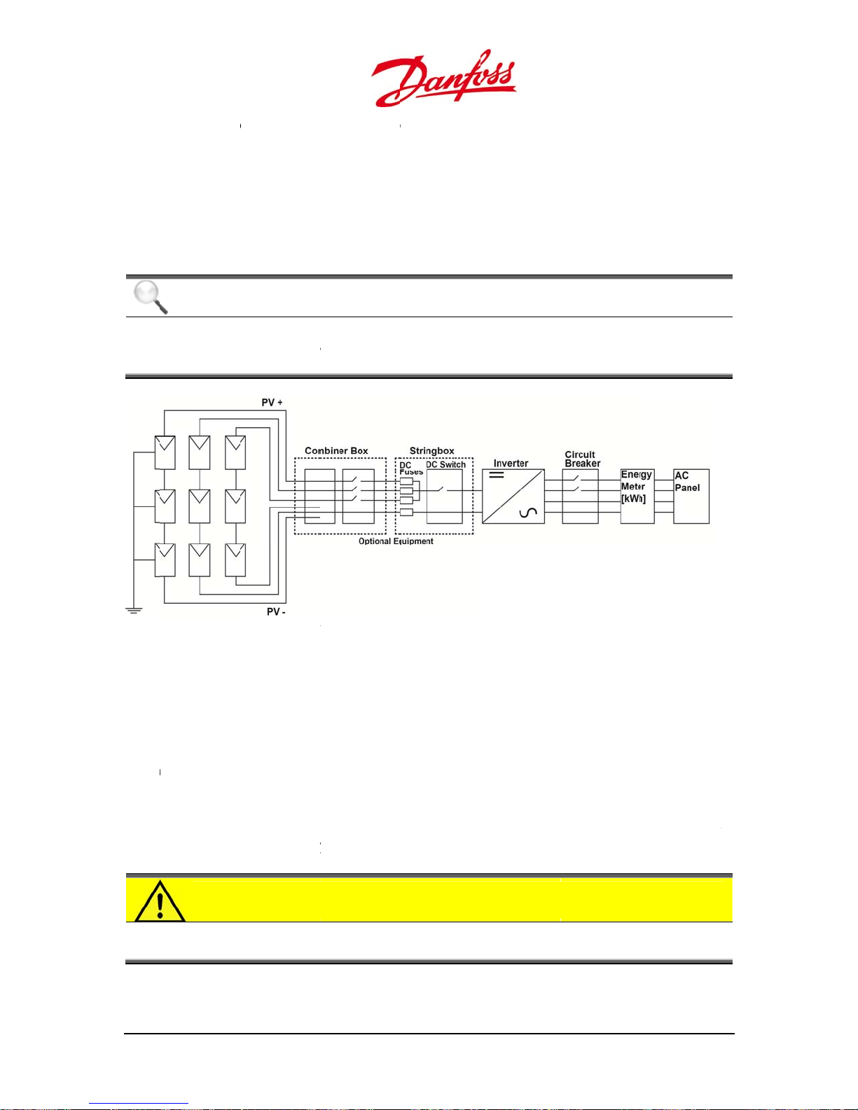
igure 4.5: Simpli
chieving saf
e performe
egulations a
ied system over
, long-term
by qualifi
d the instru
view
nd reliable
d persons a
ctions detail
peration of
nd comply
d in this
4.3.1
wo i
and
•
A
is, t
•
Vol
co
is e
User G
Cond
.
mportant cri
oltage drop.
pacity refer
he greater it
tage drop i
ductor. It is
uivalent to
CAU
he co
to prev
ide DLX UL series
uctors
teria must b
Using corre
to the curre
capacity to
the reducti
ecommend
loss in energ
ION
ductor cros
nt overhea
L00410625-01
considered
tly sized co
nt-carrying
carry curren
n of voltage
d to minimi
yield
section are
ing and fire.
in selection
ductors imp
apacity of th
.
due to cross
e the syste
must confo
f conducto
roves the eff
e conductor
section, cur
conductor
m to the rat
sizes, name
ciency of th
The larger t
ent flow an
oltage drop
ings of the N
y ampacity
PV system.
e conducto
length of th
Voltage dro
EC standard
r
e
p
2
5
•
e
g
t
o
T
T
n
e
c
h
s
o
A
o
r
d
h
e
a
o
o
d
m
b
t
i
r
n
i
e
4
e
r+PO
rGND
r
n
s
n
i
h
o
n
d
n
d
u
n
0
•
Us
resi
Sec
(e.
adequately
stance.
ure conduct
. sharp edge
sized condu
rs so that t
s).
tors with th
ey are kept
correct te
way from o
perature rat
jects that ca
ng and sunl
n damage t
ght
e insulation
4.3.2
.
CAU
he co
have th
Conn
ION
ductors mu
e correct col
ection
t be listed f
r coding to
rea
r PV applica
avoid mater
ions and th
al damage a
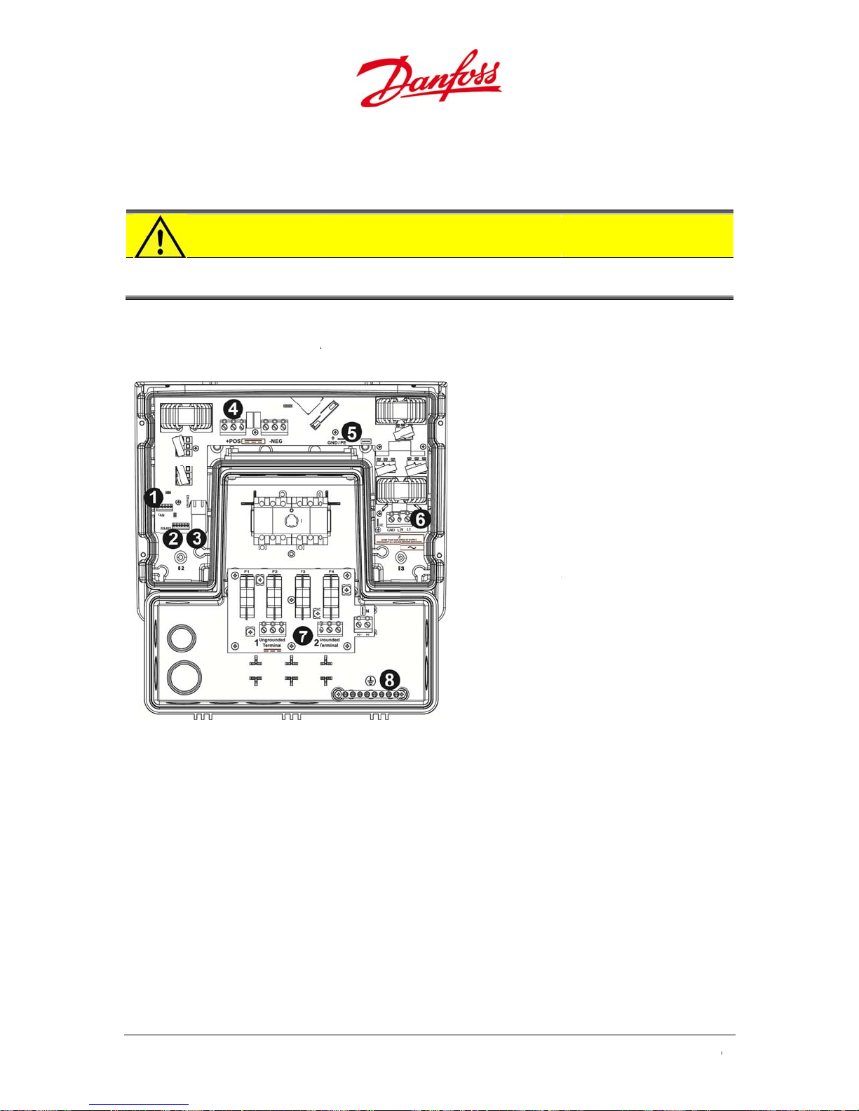
1. CAN
2. RS-
3. Eth
4. Inte
5. Inte
6. Inte
7. DC f
8. Equi
Stri
site environ
nd bodily ha
bus terminal
85 terminal
rnet connecti
nal DC termi
S and -NEG
nal DC groun
/PE
nal AC termi
use board, Str
pment groun
gbox
ment and
rm.
n
al blocks,
terminal,
al block
ingbox
ing bar,
Figure
4.6: Customer c
•
DC
connection
•
AC
connection
•
Ne
opt
ions.
work conn
can be eithe
is performe
ctions are t
26
nnection area
a negative
differently
e same rega
r positive g
epending o
rdless of the
ounded PV
the grid co
different DC
tring config
figuration.
and AC con
U
ser Guide DLX UL
ration.
ection
series L00410625-
01
u
2
D• Theand• The
e
e
d
g
d
b
o
t
a
f
e
s
w
f
e
e
w
C
c
t
o
o
w
i
o
p
t
s
o
m
h
s
t
c
m
m
s
o
o
1
d
u
e
s
t
h
h
e
i
t
e
t
e
”
a
t
o
o
e
t
h
f
b
g
S
d
t
S
s
X
v
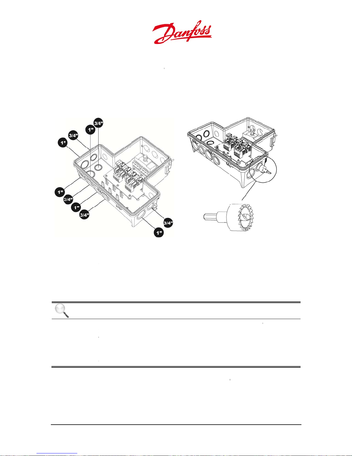
4.3.
The
spe
.1. Con
LX UL String
Stringbox c
shipped wi
knock outs
cified in the
uits
ox is equip
nnected to
h knock out
re located o
igure below
ed with kn
he bottom
for ¾” and
n the left an
.
ck-outs to fi
f the invert
” conduit fit
right sides,
the conduit
r is made of
ings.
bottom and
fittings.
non-conduc
back of the
ive material
tringbox as
Figur
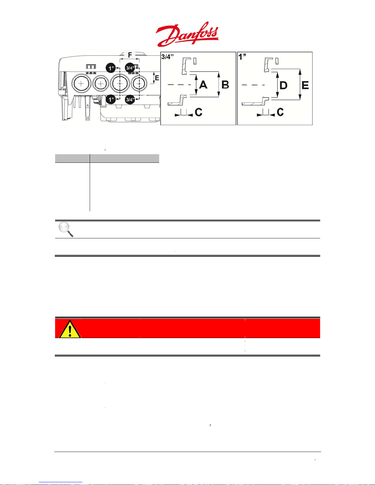
•
Us
the
•
Pos
•
Dril
•
Car
Liste
Strin
4.7: Knock out
a 1” hole sa
knock outs
ition the hol
l through th
fully file do
NOTI
For con
the en
Condui
•
DC c
•
AC c
•
Net
conduit fitt
box knock
on the Stringb
to remove
or the 1” fitti
saw in the
cover.
n any roug
E
duit hubs, u
losure
s are conne
nduits are
nduits are
ork conduit
ngs that fulf
uts:
x
the knock o
ngs.
iddle of th
edges.
e only UL Li
ted to the S
ounted on t
ounted on t
are mount
ill the follow
Figur
ts for the ¾
knock out f
ted raintigh
ringbox as f
e bottom
e right sid
d on the lef
ng criteria s
4.8: Removal o
fittings and
ce.
, or wet loca
llows:
f the String
of the Strin
side of the
ould be use
the knock outs
1- 5/16” hole
tion, hubs fo
ox.
box.
tringbox.
d for the DL
aw to remo
r entry into
HE- t UL
e
User G
ide DLX UL series
L00410625-01
2
7
4
m
e
t
The
p• The690
p
scon
g
e
e
”
”
”
4
1
C
t
n
d
G
d
t
q
f
c
f
h
8
e
o
e
t
e
b
c
c
o
e
a
a
d
o
e
i
e
t
n
s
t
o
p
m
i
u
e
E
l
d
u
a
y
d
r
d
u
/
n
e
o
y
l
y
P
S
d
o
v
0
Table
Sy
4.3.3
Prop
poin
devic
.1: Recommend
bol Siz
A
B
C
D
E
F
1
1
3
1
2
/
7
3
1
9
1
11
1
NOTI
Follow
ground
Grou
.
r grounding
for the con
es.
Figure 4.9: Size
d size for the c
/
/ 28.8 mm
9
/
/ 35.8 mm
7
” /
7.0 mm
/
/ 35.5
7
/
” / 42.5 mm
1
/
” / 45.3 mm
4
E
he guidelin
ing and tigh
ding
of the entir
uctive parts
criteria for con
nduits
s from the c
ening torqu
PV system l
and facilitat
uits to fit the Str
nduit man
.
mits voltage
s the operat
ingbox knock o
facturer reg
surges, give
ion of the ov
ts
rding conn
s a common
ercurrent pr
ction,
reference
tection
DAN
Groun
and na
ER
ing should
ional electri
•
AC input an
unding, if re
gro
res
onsibility o
Photovoltai
.41 through
res
onsibility o
•
PV
trings may
ductors are
(Fi
ure 4.6, pos.
28
d AC output
uired by Se
the installer
System Gr
690.47 of th
the installer
ave the neg
terminated
).
e carried ou
al regulatio
circuits are i
tion 250 of
unding shall
of the Nati
tive or the
t the equip
by qualified
s to prevent
olated from
he National
be installed
nal Electrica
ositive cond
ent groun
persons onl
shock hazar
the enclosu
lectrical Co
per the req
Code, ANSI
uctors grou
ing bar in th
, and comp
ds.
e and that s
e, ANSI/NF
irements of
NFPA 70 an
ded. The gr
e Stringbox
U
ser Guide DLX UL
y with local
stem
A 70, is the
ections
is the
unded
ia the GFDI
series L00410625-
01
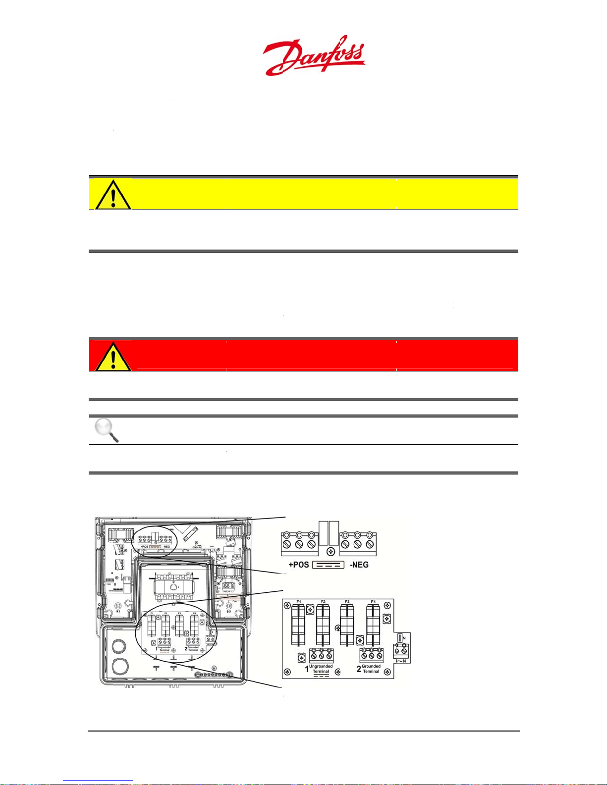
u
m
a
m
m
T
D
t
4
r
u
n
o
t
T
d
o
r
G
p
C
e
e
s
s
e
m
u
a
o
u
0
e
h
e
s
e
i
o
u
b
t
b
n
i
C
t
f
b
.
h
y
e
t
n
n
e
C
k
n
o
r
m
c
n
nt
g
a
g
m
x
n
x
•
•
•
All
Stri
Foll
reg
All
ter
etallic con
ngbox (Figu
ow the instr
rding grou
etal parts
inal GND a
duit fitting
e 4.6, pos. 8).
ctions and
ding requir
f the DLX UL
the AC ter
shall also b
pecification
ments.
inverters ar
inal block (F
bonded to
from the di
electrically
gure 4.6, pos
he equipme
ferent PV m
onded to g
6).
groundin
dule manuf
ound throu
bar in the
cturers
h the
4.3.4
he
inver
CAU
Groun
Stringb
potenti
DC C
.
C connectio
er. The inve
DAN
Always
can su
NOTI
When r
the DC
ION
ed PV cond
ox and must
als can appe
nnecti
ns include w
ter is config
ER
disconnect t
ply up to 60
E
moving th
switch is in t
ctors are gr
NOT be gro
r and possi
ns (PV)
iring from th
red with a S
he PV array
VDC to the i
lower cover
e OFF posit
unded via t
nded at an
ly damage
e PV module
ringbox.
efore starti
verter whe
to access th
on.
e GFDI to th
other point
lectrical co
s through a
g the DC co
exposed to
connection
e grounding
in the syste
ponents.
ombiner bo
nections, as
sunlight.
terminals e
bar in the
, as voltage
to the
the PV array
sure that
4.3.
User G
.1. DC T
ide DLX UL series
rminals
L00410625-01
Figure 4.10: D
terminal bloc
s
2
9

T
he i
n
o
T
P
S
4
s
e
N
The
p• Theconcon
c
m
F
e
m
C
n
m
y
t
a
g
m
m
a
h
h
k
e
u
f
r
n
a
d
u
o
n
m
,
c
e
t
s
P
s
r
a
o
F
F12NN
n
o
P-N
c
t
g
e
e
t
e
d
f
s
T
e
f
b
a
t
v
n
T
g
i
e
t
l
f
D
T
o
m
t
g
t
n
m
t
k
c
t
g
T
s
a
e
0
r
e
2.Gr
coming PV
unded Ter
onductors s
inal inside t
hall be termi
e Stringbox
nated at the
.
1.Ungroun
1, F2, F3: DC
4: Ground fu
. Ungrounde
for the ungr
. Grounded
the ground
: Receptacle
between ph
-N: Terminal
conductor.
ed Termina
use holders.
e holder (GF
d Terminal:
ounded PV c
erminal: Ter
d PV conduc
or monitorin
ases and neu
lock for the
and
I).
erminal block
nductors.
inal block fo
ors.
the voltage
ral.
eutral
he
+PO
4.3.
A PV
conn
have
the
•
de
Figure 4.11:
V conductor
and –NEG t
Figure 4.12: Ter
NOTI
The co
perfor
.2. Arra
tring consis
cted in par
a large volta
EC and the
grounding
end on the
inverter is d
figuration
figuration.
use board in th
s go throug
rminal bloc
inals in invert
E
nection req
ed by quali
Configu
s of a certai
llel forming
e range, an
odule man
configurati
odule tech
elivered fro
s a standard
e Stringbox
the DC swit
s in the low
r lower compar
ires remova
ied person
ation
number of
n array and
several fea
facturer inst
n of the PV
ology.
the factory
but may als
h in the Stri
r inverter c
ment
l of the inver
only!
V modules
attached to
ible PV strin
uctions wh
rray and th
with a nega
be deliver
gbox, and
mpartment.
POS: Positive
+
EG: Negative
ter lower co
onnected i
he inverter.
configurat
n configurin
connection
ive ground
d for a posi
re then ter
erminal bloc
terminal blo
er, and mus
series. Strin
he DLX UL i
ons are pos
g the PV arr
to the DC te
d PV array
ive ground
inated at th
k
be
s can be
nverter serie
ible. Follow
y!
rminals
d PV array
s
30
U
ser Guide DLX UL
series L00410625-
01
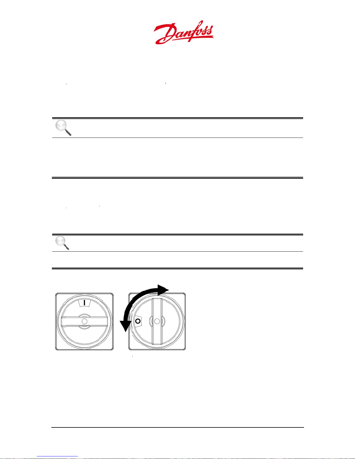
u
The
acom
anegcon
n
4
S
w
g
T
D
d
o
n
a
m
a
C
a
t
w
t
n
C
r
r
a
a
o
n
d
o
:
n
t
t
h
P
e
h
n
u
h
o
p
g
;
C
r
n
e
i
l
s
;
m
n
n
g
o
w
r
e
u
h
e
o
n
l
N
F
u
i
g
w
6
e
e
o
m
n
e
a
h
•
•
arr
Arr
ide
positive gr
y configurat
partment a
y configur
ative DC ter
nected in p
tical for eve
unded PV
ion by the c
d in the Stri
tion depen
inal blocks
rallel. Due t
ry string.
rray config
nnection to
gbox and t
s on the m
have three
the inverter
ration diff
the DC term
e DC switch
dule techno
airs of input
having one
rs from the
nal blocks i
in the Strin
ogy used. B
, which allo
MPP-tracke
egative gro
the inverter
box.
th the posit
three strin
the PV po
nded PV
lower
ve and
s to be
er should b
4.3.
The
the
Strin
NOTI
Maxim
under
propor
from th
from th
.3. DC S
tringbox is a
iring that ru
box.
NOTI
Before
the DC
E
um Voltage
ny conditio
ional to the
e nameplate
e nameplate
itch
tached to t
s from the
E
emoving th
switch is in t
The open ci
s. The volta
emperature
rating and a
rating.
e bottom of
V array. A D
lower cove
e OFF posit
rcuit voltage
e generated
at lower te
t higher tem
the inverter,
disconnect
to access th
ion, and the
, VOC, must n
by PV mod
peratures t
peratures th
and provide
switch is pr
e connectio
PV array cab
I = O
0 = O
ver exceed
les is invers
e PV voltag
PV voltage
s PV string c
vided and
terminals e
les are disco
F
00 VDC
ly
increases
decreases
nnection vi
ounted in t
nsure that
nected.
e
Figu
e 4.13: DC disco
he
600V
C switch is r
c
ted at:
25A
User G
ide DLX UL series
L00410625-01
nect switch
3
1
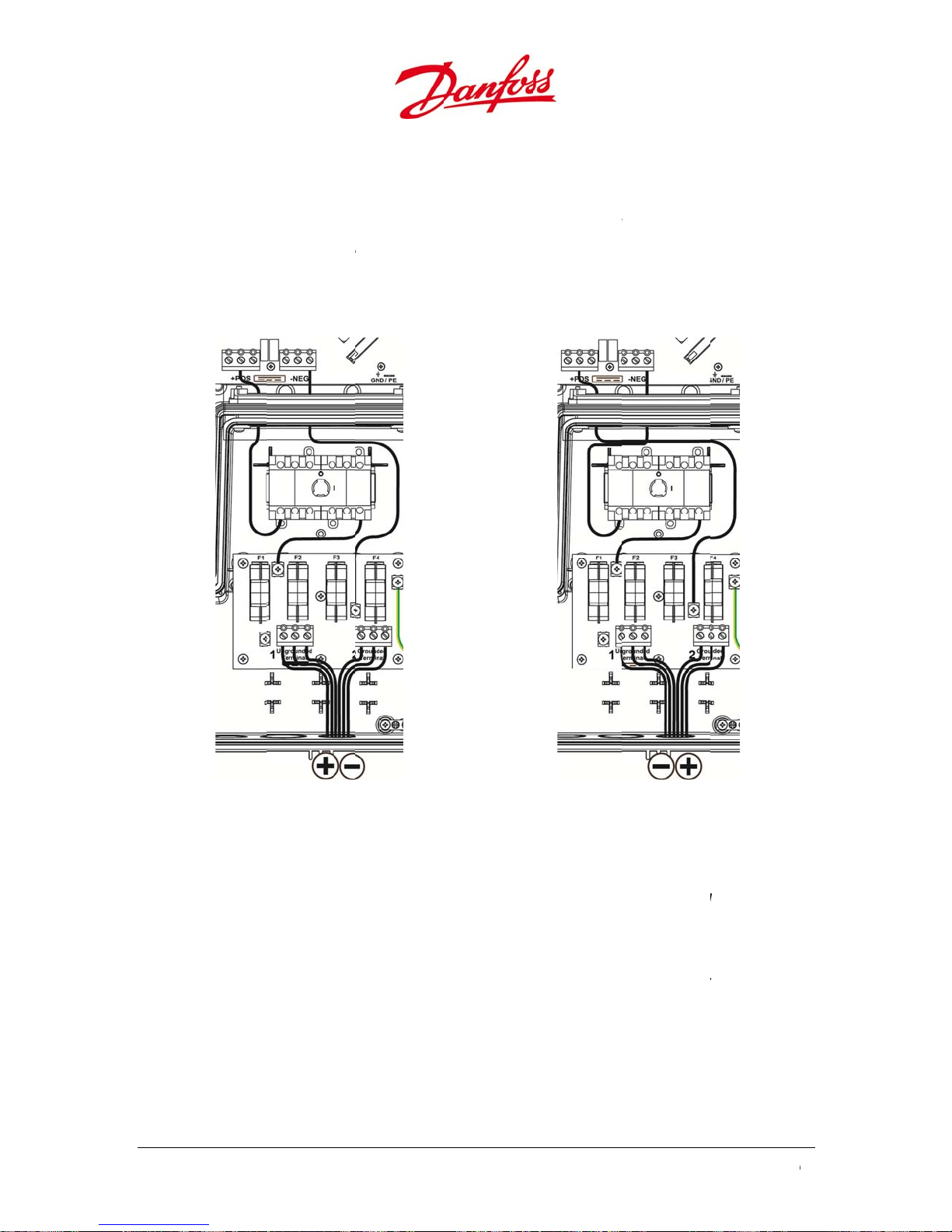
4
n
f
g
g
T
i
h
Term
Term
Term
h
Term
c
Tigh
t
h
m
t
e
s
N
p
o
e
u
n
a
T
o
N
f
P
e
o
d
d
o
S
g
c
g
N
a
w
i
e
c
n
.
o
r
h
v
d
o
e
a
u
w
v
r
s
2
1
a
c
t
u
o
t
S
P
i
d
t
E
0
S
c
4.3.
The i
speci
confi
Strin
he f
.4. Posi
verter is s
ied at the ti
urations is
box and th
gure below
Negative
ive Grou
ipped with
e of order.
he connecti
+POS and –
hows the di
Grounded
ded PV
negative
he differen
n to the Un
EG termin
ference bet
V String
tring
rounded st
e between n
rounded an
l blocks in t
een negati
ing config
egative and
d Grounded
e inverter lo
e and positi
Positive G
ration, if no
positive gro
terminal bl
er compar
e grounded
ounded PV
hing else is
nded PV
cks in the
ment.
strings.
tring
Figure 4.14: N
egative ground
To c
•
Stri
•
Stri
•
in t
•
blo
•
ange from
inate the
ngbox.
inate the n
ngbox.
inate the g
e inverter l
inate the u
k in the inv
tening torq
egative gr
ositive con
egative con
rounded po
wer compar
ngrounded
rter lower c
e is 1.47 ft-l
32
d PV string
und to Pos
uctors at th
uctors at th
sitive condu
tment.
negative co
mpartment
bf / 2.0 Nm f
tive groun
terminal bl
e terminal bl
tor from th
ductor from
r all termin
Figure 4.15: Po
:
ck labeled
ock labeled
fuse board
the DC swit
ls.
itive grounded
. Grounded
1. Ungroun
t the +POS
h at the -N
U
ser Guide DLX UL
V string
n the
ed in the
erminal blo
G terminal
series L00410625-
k
01
u
4
Thehav• Thecop
t• Term
h• Term
4
e
Turn
m
e
c
n
o
m
/
y
w
p
C
e
n
T
r
G
r
C
G
T
u
c
m
c
u
0
i
c
s
n
n
f
D
g
C
r
c
r
t
k
a
e
V
r
o
c
o
e
d
c
a
h
m
p
o
e
e
D
n
e
o
u
m
t
m
u
m
a
t
b
s
n
e
s
D
o
m
c
m
m
a
d
d
e
d
e
n
t
p
e
d
i
e
b
a
o
D
t
e
d
t
4.3.
•
ng of 194°F
rati
•
Foll
ow the safet
ins
tig
the
4.3.
If the
start.
curre
nts are gene
.5. Con
DC voltage
e a maximu
DC conduct
per conduct
allation.
inate the u
ten the scre
inate the g
screws by a
NOTI
PV syst
have a
.6. Reve
positive and
he inverter
ection Pr
n the cond
rating of 6
or must be s
ors between
90°C for all
instruction
ngrounded
s by applyi
rounded co
plying 1.11
E
ms with GF
additional
rsed DC
negative te
will not be d
ated in the
ocedures
ctors conne
0VDC at any
zed for corr
10 AWG an
onnections.
and specifi
conductors
g 1.11 ft-lbf
ductors at t
t-lbf / 1.5 N
I that incor
rounding c
onnectio
minals are r
amaged du
onductors.
ting the PV
perating te
ct temperat
6 AWG / 6
ations from
t the termin
/ 1.5 Nm of
e terminal
of torque.
orate the sy
nnection.
n
versed duri
to internal r
array to the i
perature.
re rating an
m2 and 16
the module
l block labe
orque.
lock labele
stem groun
g connectio
verse block
nput of the i
d sunlight re
m2 and tem
anufactur
led 1. Ungro
2. Grounde
ing connect
n, the invert
ing diodes,
nverter mus
sistance. Us
erature
rs regarding
unde
ion must no
, and
, and tighte
r will not
ut high
n
Proc
•
•
Re
•
Ch
•
Dis
•
Rec
onnect the c
DAN
Be awa
current
dure
OFF the A
DAN
he PV
OFF, d
and wa
ove the PV
ck if the ter
onnect the
ER
e of high cu
s are genera
circuit brea
ER
conductors
e to power f
it until the P
onnectors
inals are dis
onductors f
onductors t
rents! If the
ed in the co
er(s) and th
re still charg
eding PV m
modules d
charged by
om the ter
the correct
C terminal
ductors, wh
DC switch.
ed after the
odules. Alwa
not feed p
sing a volt
inal block.
erminal blo
are reverse
ich can pos
C switch o
ys turn OFF
wer.
eter.
.
during inst
shock hazar
the Stringb
he remote
llation, high
ds.
x is turned
C switch
User G
ide DLX UL series
L00410625-01
3
3
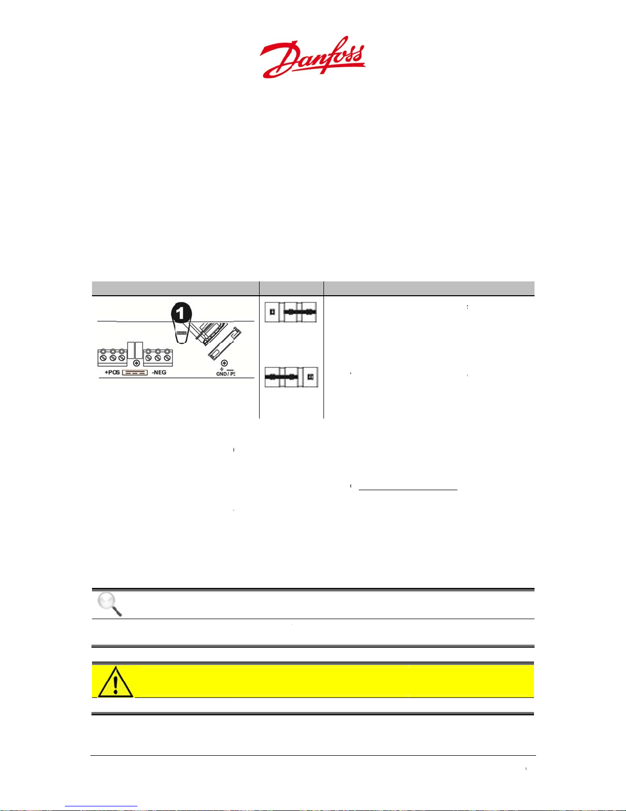
•
Test
4
T
u
i
s
4
e
m
p
T
A
k
y
e
g
g
q
y
a
J
p
e
g
h
e
m
a
t
c
g
o
n
C
v
0
8
e
C
X
T
T
m
o
e
c
u
e
r
n
o
i
o
t
W
5
u
e
s
k
r
r
h
u
)
e
v
t
p
v
n
u
t
o
e
a
T
j
t
t
T
j
.
o
t
u
c
m
n
e
d
t
d
t
h
e
s
m
C
m
e
e
h
f
g
o
s
2
0
g
t
i
bre
the polarit
ker(s).
using a volt
eter befor
turning ON
the DC swit
h and the A
circuit
4.3.
he j
arran
posit
requi
In ca
“Fuse
Table
Inv
1. Ju
setu
.7.
um
mper abov
ement of t
oned for a n
rements fro
e of a mism
fault.”
.2: Jumper posi
rter lower
per monitorin
.
er Positi
the - NEG t
e DC conne
gative gro
the modul
tch in groun
ion for the DC g
ompartme
the grounding
n for Sy
rminal bloc
tion accordi
nded PV st
manufactu
ding setup t
ounding config
t Top v
tem Gro
in the inver
g to the gr
ing configu
er the jump
e following
ration
iew Syst
Neg
he
righ
Posi
he
pins
nding Se
er lower co
unding setu
ration. Depe
r must be r
message wil
em
tive groun
umper shor
most pins (
tive ground
umper shor
tup
partment
p. The jump
nding on th
positioned.
l appear in t
ed PV con
-circuits the
efault).
ed PV Confi
-circuits the
onitors the
r is
grounding
e display:
iguration:
two
uration:
two leftmos
4.3.5
he
brea
Verif
conn
•
Sin
•
Sin
•
Fre
AC C
.
C connectio
ers to the A
that the AC
cting the in
le phase 24
le phase 20
uency rang
NOTI
The DL
CAU
he AC
nnecti
includes w
terminal bl
grid parame
erter to the
VAC/120VAC
VAC/120VAC
: 59.3 to 60.
E
UL inverter
ION
output / Ne
ns (Grid
ring from th
ck of the in
ers are com
grid:
YE
Hz
provides a
tral of the i
AC distribu
erter (refer t
atible with
oltage outp
verter is not
tion panel t
o 4.3.2 Conn
he inverter
t range fro
bonded to g
rough one
ction Area).
pecification
184 VAC to
round.
r more circu
before
76 VAC.
t
34
U
ser Guide DLX UL
series L00410625-
01
u
o
e
4
m
s
t
i
d
T
e
e
e
V
5
Themax
The
d• The
m
N
u
G
T
F
r
s
e
o
n
u
n
C
p
a
n
y
y
s
o
k
c
t
n
h
N
)
n
o
o
t
-
e
e
g
t
E
t
n
b
/
n
u
s
e
m
o
o
T
n
d
h
L
C
e
m
d
d
a
A
c
t
C
t
t
n
2
n
p
t
o
b
l
b
d
c
c
d
r
n
t
2
a
p
b
y
t
t
u
t
a
k
e
t
o
c
d
i
r
t
n
a
a
a
s
e
b
AC p
Phas
Table
Ter
Pha
Neu
Equ
con
hes
phas
whil
L1 and N or
120
Also,
by connecti
three
phases.
WAR
To red
having
DAN
urn O
inverte
wer system
power syst
.3: The different
(Abbr.)
e conductor
ral conduct
pment grou
uctor (GND)
three cond
is provided
loads mus
AC
ING
ce the ris
multi-wire
ER
F the AC cir
to the grid
are found i
ms usually
AC conductors
(L1/L2)
r (
d
ctors are co
by connecti
L2 and N pr
t be distribu
g to a three
of fire, do
ranch circ
uit breaker(
o prevent el
both com
ave three c
Descripti
he ungrou
A circuit co
ungrounde
An electrica
nected to t
n of either
vide 120 V
ed evenly b
phase syste
ot connec
its connec
) and the D
ctrocution.
ercial/indus
nductors:
n
nded conduc
ductor carryi
conductors.
l path to grou
e service en
1 and N or L
.
A
tween L1 a
the load m
to an AC
ted.
switch befo
rial and resi
ors, which ca
g the unbala
nd, designed
trance panel
and N. L1
d L2 to kee
ust be distri
ircuit brea
re connectin
ential/offic
ry current to
nced current
o carry fault
. The typical
nd L2 provi
the system
uted evenly
er panel
g the
application
he load.
the
urrent.
120 VAC singl
e 240 VAC
n balance.
between th
.
e
NOTI
E
Single
signific
hase invert
ntly increas
4.3.
Depe
perfo
.1. Con
nding on s
rmed differe
ection Pr
upply volta
ntly.
•
current carr
imum 6 AW
•
current carr
an
voltage. En
AC conduct
te
perature rat
User G
ide DLX UL series
ing conduc
G /16 mm2.
ing conduc
ure complia
rs must be
ing of 194°F
L00410625-01
rs connecte
unbalance
ocedures
e configur
ors on the A
nsure compl
ors on the A
ce with the
etween 10
90°C for all
to a three
system vol
tion the c
C side must
iance with e
C side must
state and fe
WG and 6 A
onnections
hase primar
ages.
nnections
e rated for
ectrical reg
e rated for
eral electric
WG / 6 mm
power sou
o the inve
he current a
lations!
he appropri
l regulation
2
and 16mm
ce must not
rter must
d be
te current
s!
2
nd with a
e
3
5
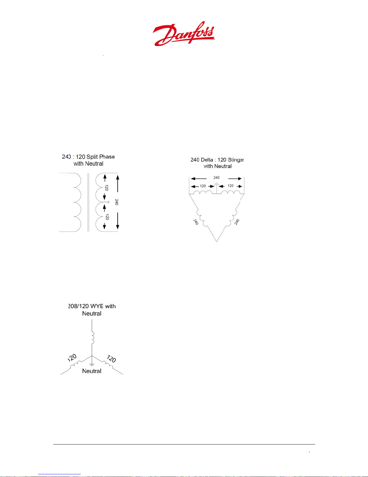
•
econ
t
Term
Tigh
e
A
y
o
u
c
h
A
o
s
m
e
c
o
c
m
p
p
y
m
o
s
t
e
e
0
Wh
•
Foll
ins
•
•
•
Ch
Singl
n selecting
ductors.
ow the safet
allation.
inate the c
tening torq
ck that the
e Phase wit
C conduct
instruction
nductors to
e of the ter
onnection is
Neutral
rs, resistanc
and specifi
the corresp
inal screws
performed
should be
ations from
nding termi
is 1.5 Nm / 1
orrectly.
inimized b
the conduit
nals in the c
.11 ft-lbf.
selecting a l
anufactur
nnection ar
arger size of
rs regarding
a.
VAC phase to
240
V
120
phase to
AC
phase
neutral
240 V
AC
120 VAC
hase to pha
hase to neu
e
ral
208
120
V
AC
V
phase to
AC
phase
neutral
phase to
36
U
ser Guide DLX UL
series L00410625-
01

u
Term
h• Term
h• Term
Term
nabo
w
n
e
t
w
1
t
e
t
e
u
q
r
k
h
u
t
m
t
m
u
e
g
w
d
d
g
e
e
A
e
N
a
fl
r
b
a
e
e
l
o
t
e
o
f
•
•
•
rig
rig
Stri
the
Co
the
bet
inate the li
t side of the
inate the li
t side of the
inate the n
ngbox.
inate the e
Stringbox.
nect the bo
ve the N-N t
DC ground
een the ph
Figure 4.
ne 1 conduc
inverter low
ne 2 conduc
inverter low
eutral cond
uipment g
ding strap
rminal bloc
erminal in t
ases and ne
6: Connections
or at the ter
r compart
or at the ter
r compart
ctor at the t
ound cond
(white or gr
in the Strin
e inverter lo
tral.
for single phase
minal labele
ent.
minal labele
ent.
erminal bloc
ctor at the
y colored) b
box and th
er compart
with neutral
L1 on the
L2/N on th
k labeled N-
rounding b
tween the
unmarked
ment. This is
C terminal
AC termin
in right sid
r in the low
at receptac
receptacle t
to monitor
lock in the
l block in th
of the
r right side
e labeled N
the right o
he voltage
f
User G
ide DLX UL series
L00410625-01
3
7

Singl
Term
h
Term
h
Term
h
l
1
t
e
t
e
q
r
f
t
m
t
m
o
t
d
d
h
A
e
g
b
a
S
0
e
e Phase wit
VAC phase to
240
no Neutra
phase only
Figure 4.
•
•
•
38
inate the li
rig
t side of the
inate the li
rig
t side of the
inate the e
ne 1 conduc
inverter low
ne 2 conduc
inverter low
uipment g
: Connections
or at the ter
r compart
or at the ter
r compart
ounding c
or Delta grid wi
minal labele
ent.
minal labele
ent.
nductor at t
h no neutral
L1 on the
L2/N on th
e groundin
C terminal
AC termin
bar in the
U
ser Guide DLX UL
lock in the
l block in th
tringbox.
series L00410625-
01
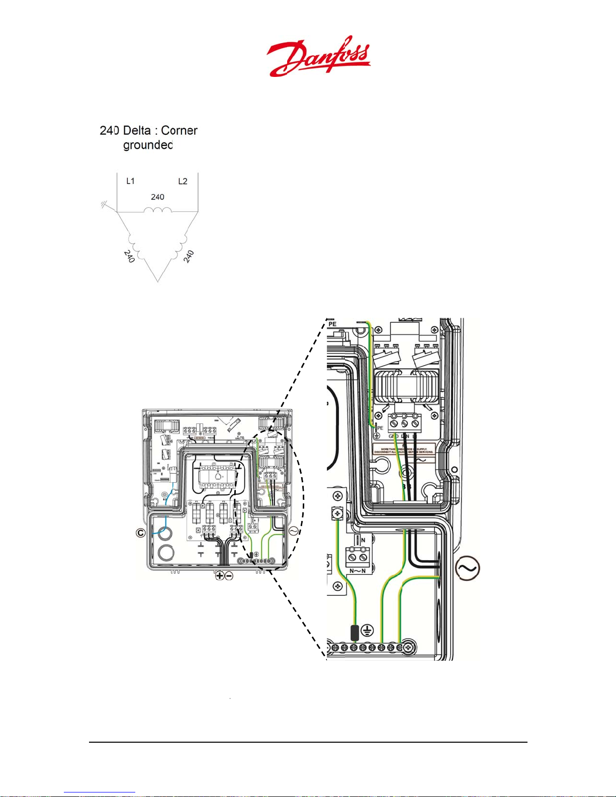
u
a
Term
h
o
n
t
e
l
t
m
d
d
d
W
A
b
Delt
: Corner Gr
240
VAC phase to
unded
phase only
Figure 4.18: Co
•
User G
inate the li
rig
t side of the
ide DLX UL series
ne 1 conduc
inverter low
L00410625-01
nections for De
or at the ter
r compart
ta corner groun
minal labele
ent.
ed and Delta
L1 on the
ye
C terminal
lock in the
3
9
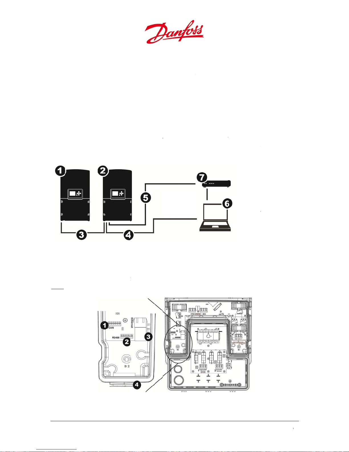
Term
c• Term
n
e
h
t
T
n
r
t
t
6
e
h
o
g
n
u
s
d
F
n
s
U
q
r
a
d
n
t
a
m
n
t
e
e
o
d
v
s
u
e
t
n
e
m
h
d
c
e
a
o
s
o
d
g
n
k
r
v
o
u
e
S
c
ked
c
m
n
m
e
o
t
e
m
a
e
0
e
•
blo
•
Co
lab
rig
vol
4.3.6
he i
Ethe
direc
inver
inate the g
k in the rig
inate the e
nect the gr
led PE to th
t of the DC
age betwee
Netw
.
verter is eq
net provide
ly connecte
ers. RS-485
rounded ph
t side of the
uipment g
unding str
e left side of
round termi
ground an
ork Con
ipped with
communic
or via a rou
allows com
ase conduct
inverter low
ounding c
p (green an
the AC termi
nal in the in
the ground
ection
hree comm
tion betwe
er/switch. C
unication w
or at the ter
r compartm
nductor at t
yellow colo
nal block an
erter lower
ed phase.
nication int
n the integr
AN allows c
ith certain th
inal labele
ent.
e groundin
red) betwee
the unmar
ompartmen
rfaces: Ethe
ted web-ser
mmunicati
ird party eq
L2/N on th
bar in the
the flat re
recepta
t. This is to
net, CAN, a
ver and a co
n between s
ipment.
1. Foll
2. Mas
3. CAN
4. Eth
5. RS-4
6. Co
7. Dat
AC terminal
tringbox.
eptacle
le to the
onitor the
d RS-485.
puter, eith
everal
wer inverter
er inverter
bus cable
rnet cable
85 cable
puter
logger
r
4.3.
If sev
prior
.1. Con
ral inverter
to the Start
igure 4.19:Con
ection Pr
are connec
p procedur
ection without
ocedures
ed together,
to benefit fr
Figure 4.20: N
etwork
all inverters
om single in
twork connecti
must be con
tallation set
n
nected to th
up.
CAN bus
40
U
ser Guide DLX UL
series L00410625-
01
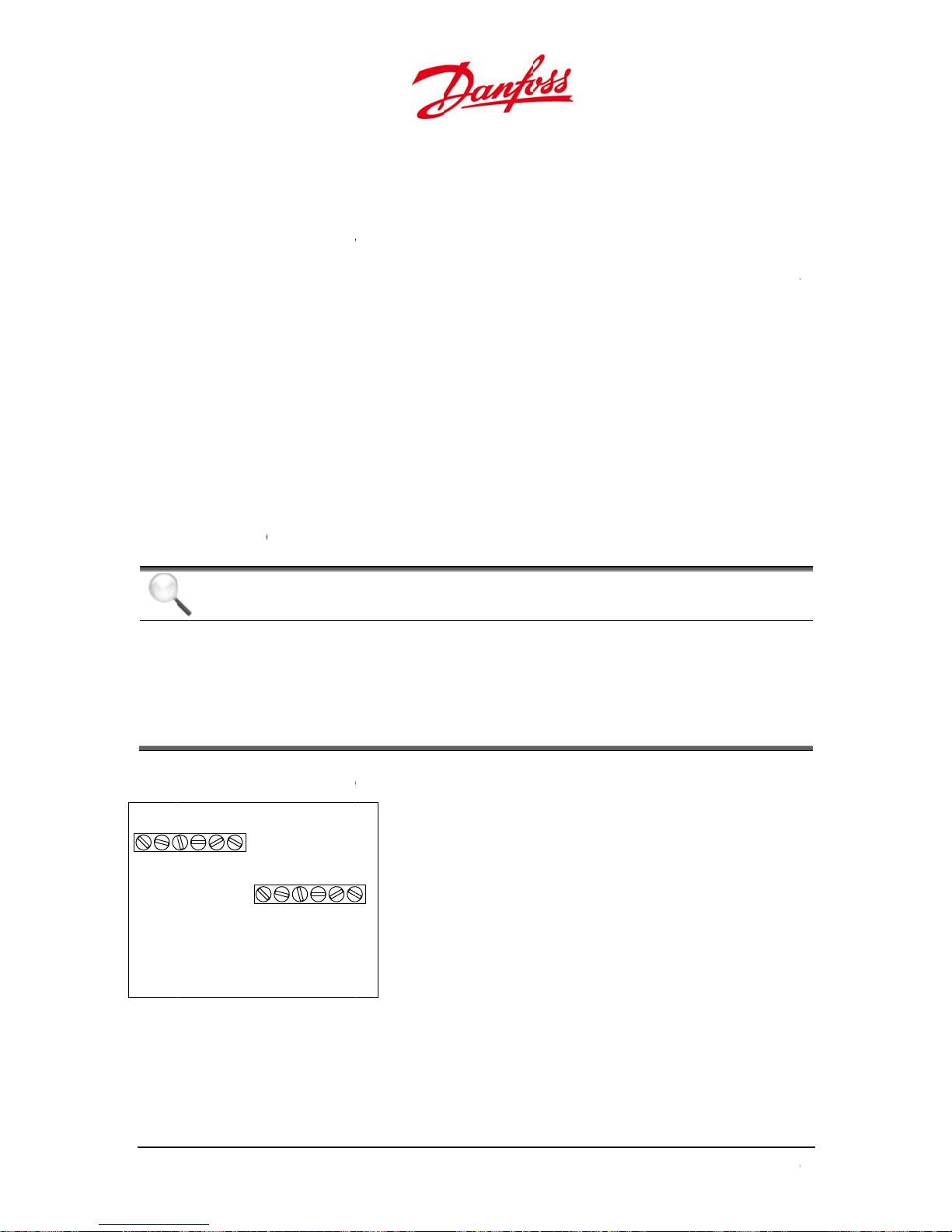
u
A
S
0
N
-120• Term
Tigh
a
C
e
T
a
d
C
s
i
a
y
r
G
N
D
A
e
w
r
T
o
e
q
T
o
e
q
f
i
g
t
p
B
(
+
)
2
W
4
h
c
u
o
u
o
t
e
o
r
e
m
o
y
n
H
n
A
n
r
n
,
a
l
4
s
A
s
a
s
m
o
o
d
5
d
5
b
4
f
0
t
N
t
N
1. C
2. R
•
Eth
ernet: Use C
10
•
CA
m.
•
RS
485: Use CA
-
-
-
•
N bus termin
-485 terminal
m.
: Use CAT5
0 m.
inate the c
Ethernet:
CAN:
RS-485:
ten the con
al
T5e or bett
or better,
5e or bette
bles at the t
Plug t
he c
both
of tor
he c
both
of tor
uit fittings
r, with size
ith size 24 A
, with size 2
erminals in t
he Ethernet
nductors m
nds: i.e. H c
ue.
nductors m
nds: i.e. A c
ue to tighte
irmly.
3. Ethe
4. Cabl
4 AWG / 0.2
G / 0.21 m
AWG / 0.21
e connecti
able directl
st be termi
nnected to
st be termi
nnected to
n.
net port
gland
1 mm2 and a
2
, with a m
mm2, with a
n area as fol
into the RJ
ated to the
, L to L etc.
ated to the
, B to B etc.
maximum t
ximum total
maximum t
ows:
5 port.
ame labele
pplying 0.1
ame labele
applying 0.1
tal length o
length of 5
tal length of
terminals a
ft-lbf / 0.2
terminals a
ft-lbf / 0.2
0
m
m
CAN
LHCOMGND
NOTI
Cable
CAN an
If any k
the dat
If the s
“Maste
nd RS-485 c
AN
COMGNDLH
E
hielding: It
d RS-485 wit
nd of datalo
logger.
stem consis
”
onnection
RS-485
A(-)
B(+)
GND
A(-)
s recommen
h the GND a
ger is conn
of two or m
inout
ded to mou
the receive
cted to an i
re inverters
t the cable
s end.
verter, then
, then only
hielding for
only mount
ount the shi
both the
the shield at
eld at the
User G
ide DLX UL series
L00410625-01
1

6
n
a
m
g
v
t
To d
c
4
-
J
p
e
m
r
:
r
t
h
o
t
e
n
o
n
t
n
d
h
u
i
a
r
j
t
n
m
r
e
v
b
m
c
J
e
e
v
n
e
v
a
t
c
h
e
e
e
o
m
T
s
T
s
4
b
o
a
n
0
s
4.3.
Whe
activ
mini
•
Sin
•
Se
on
the
•
•
Be
Table
Con
.2.
um
several inv
tes the ter
izes signal
le inverter
eral inverte
he first inve
inverters be
isconnect t
areful not t
.4: Jumper posi
nection Are
er Positi
rters are co
ination resis
eflections in
The two pi
rs connecte
ter and on t
ween the fir
e pins the j
bend the pi
ion for the term
n for Te
nected, the
ance when
the cables a
s can be ter
: The maste
e last invert
st and last in
mper must
ns when re
nation resistan
ump
mination
umper locat
he pins are t
d helps to a
inated or di
-follower co
r in the link
erter in the
e pulled up
oving or ins
e
r Position
Resistan
d behind t
erminated (s
void interfer
sconnected.
figuration r
d series. Th
linked series
and placed
alling the ju
Pins
he pin
he pin
e
e CAN / RS-
hort-circuite
nce.
quires term
pins must
.
nly on one
per!
are termin
are discon
85 terminal
d). This
inated pins
e open on
f the pins.
ted.
ected.
1. CA
2. RS
N termination r
485 terminatio
sistance
resistance
42
U
ser Guide DLX UL
series L00410625-
01
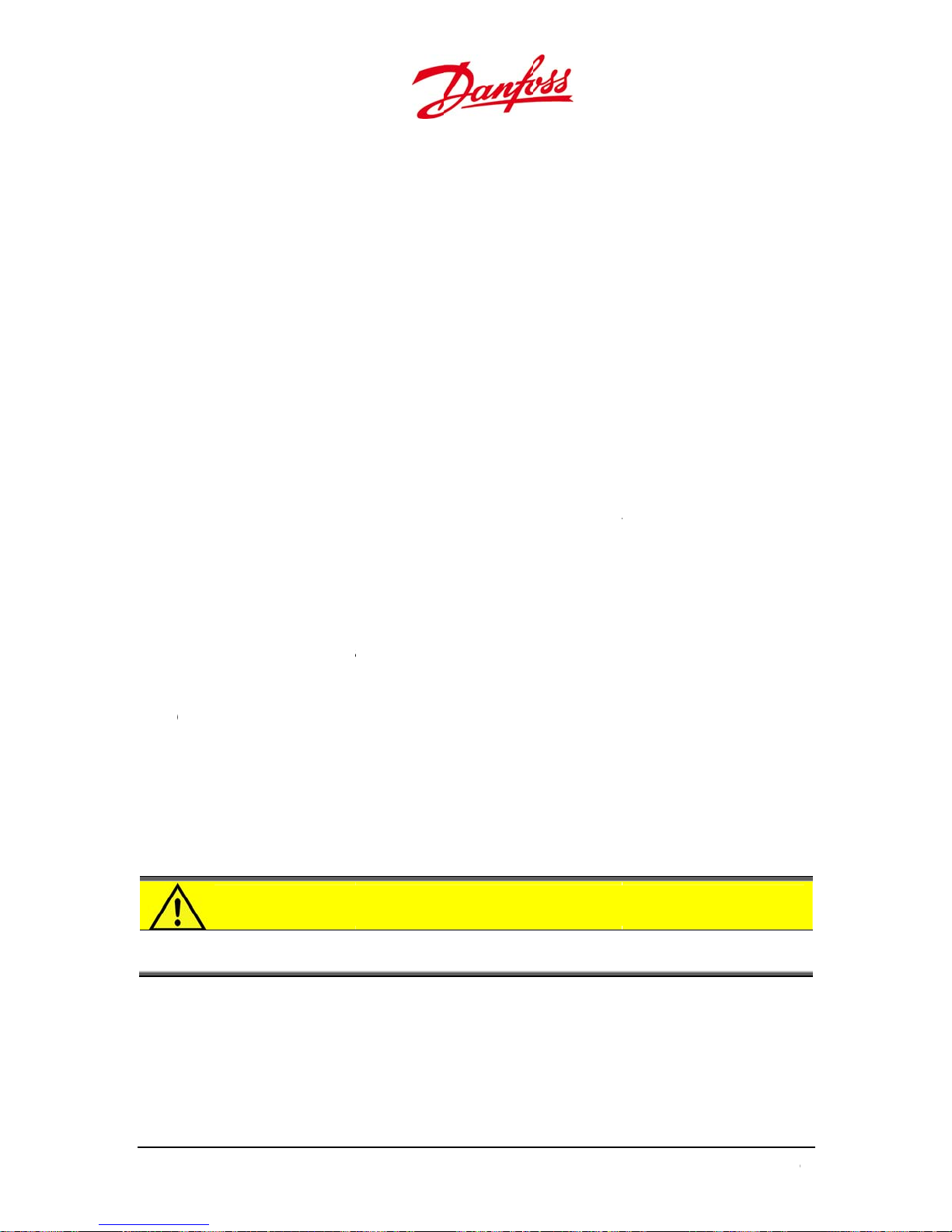
u
o
V
o
Ju
O
n
k
t
t
e
t
t
t
t
n
t
t
p
c
e
p
a
a
f
T
h
g
e
e
o
s
d
o
d
s
a
t
r
n
r
g
e
o
a
o
e
t
e
n
u
a
o
o
c
r
o
e
r
u
s
o
r
o
c
h
u
o
n
n
e
d
C
t
d
t
t
n
v
e
o
n
e
d
t
e
n
r
e
e
N
e
4
r
e
e
4.3.7
M
Chec
.
unting:
- Check tha
P
wiring:
- Check tha
environm
- Check tha
C
nnection:
- Check tha
- Check tha
D
C side:
- Verify that
- Check tha
A
C side:
- Verify that
G
rounded co
- Check tha
switched.
mpers:
- Check tha
correctly
D
isconnects:
- Verify that
disconne
easily acc
vercurrent
- Verify that
correctly,
I
verter cove
- Ensure th
the cover
lbf.
s befor
the bracket
the PV cabl
ntal conditi
the wiring i
the PV con
all connect
the PV open
the DC pola
the AC con
ductors:
the equipm
the jumper
ositioned.
all current-c
ted, and tha
ssible.
rotection:
the overcur
nd capable
r:
t no cables i
irmly to the
Start U
and the inv
s are rated f
ns.
performed
uctors are c
rs and cabl
-circuit volta
rity is correc
uctors on ar
ent groundi
for the gro
rrying cond
the breaker
ent protecti
f being cha
terfere with
housing. Re
p
rter are corr
r the PV cu
ccording to
rrectly torq
glands are c
ge, V
uctors on b
s and DC dis
the sealing
ommended
, doe
OC
.
correctly c
g conducto
nding setup
n on both t
ged witho
ctly mount
rent and for
local and fe
ed to the D
orrectly tigh
not excee
nnected to
s are proper
and for the
th the DC a
onnects are
e DC and th
t touching li
f the invert
tightening t
d and secur
the expecte
eral electric
terminals.
ened and s
600 V
DC
he AC termi
ly sized, and
ermination
d AC side ca
located corr
e AC side ar
e contacts.
r lower cov
rque is 1.0
d.
al regulation
aled.
als.
not fused o
esistance ar
n be
ectly and ar
sized
r, and fasten
m / 0.74 ft-
s.
CAU
User G
Verify t
housin
ide DLX UL series
ION
at the lowe
and dama
L00410625-01
cover is cor
es the electr
ectly tighte
nic compo
ed, so that
ents.
o moisture
nters the
3

S
5.
T
c
m
m
i
i
I
n
V
l
eeno
i
A
n
n
T
v
t
e
T
e
T
e
S
r
u
o
D
t
r
n
.
r
v
C
p
u
n
o
r
m
n
r
e
r
t
A
o
d
p
g
o
o
v
e
e
c
t
r
W
C
a
r
t
e
t
s
e
t
-
i
t
n
t
c
o
e
n
a
p
L
.
t
b
a
e
n
t
m
m
r
m
C
o
y
u
e
n
d
n
0
e
e
m
e
his
startup or
The
(fro
AC S
•
DC S
TAR
hapter provi
up of the in
commission
inimum vol
the PV syst
de
urn ON th
de
UP
des instructi
erter require
ing the inve
age require
m) and a mi
AC circuit b
ns to ensur
s the presen
ter if one of
ents to sta
imum of 7
eaker(s).
a safe start
e of AC and
he voltage s
t up DLX UL i
.
DC
up of the D
DC voltages
ources is no
nverter serie
X UL inverte
Do not atte
available.
s are 184V
r series. The
pt to start
and 230V
A
DC
5.1.
5.1.1
•
Whe
230
enab
.
Singl
e Inverter
•
Wh
Mult
1. C
N
•
Co
via
one inverter
the
tra
•
Eac
h follower in
Up.
•
urn ON th
nitial
the inverte
and a DC
DC
e the config
Cust
n both the
ugh power,
ple Inverte
necting all i
master inve
sferred to al
DC switch(e
tart
is started fo
power great
ration of ce
mizing
C and the
he installati
s Connecte
verters via t
The Start U
ter the confi
l the other f
erter is aut
s).
the first tim
r than 7 W
tain values
he Inve
C disconnec
n menu is d
he CAN bus
can then be
uration set
llower invert
matically as
e, , with min
, an installa
D
nd operatio
ter Sett
s are turned
isplayed on
nables the
carried out
ings of time,
ers on the n
igned an ID
mum availa
ion menu is
al settings.
ings
ON and the
he LCD scre
onfiguratio
n any inver
date, langua
twork.
umber fro
le voltages
utomaticall
inverter is s
n.
of all invert
er, and if co
ge and grid s
the master
f 184 VAC,
displayed t
pplied with
rs in a plant
figured as
ettings will b
uring Start
o
NOTI
If multi
44
CAN b
single i
E
le inverters
s, and recei
stallation s
are connect
ing sufficien
tup.
d together,
AC and DC
ll inverters
power, befo
ust be con
e Start Up to
U
ser Guide DLX UL
ected to th
benefit fro
series L00410625-
01

u
-
nequ
e
The
U
2
T
a
n
T
e
n
c
u
T
m
m
m
e
t
a
I
S
e
e
f
e
n
O
m
o
w
e
e
e
n
t
e
t
l
l
b
m
l
y
e
w
e
v
a
e
m
t
e
s
k
e
u
T
f
T
f
n
e
u
o
n
b
w
r
p
y
t
t
A
n
a
w
u
b
o
s
a
n
c
a
e
4
2. RS
•
Co
inv
•
Eac
h inverter m
Gui
dely:
•
485
necting the
ipment. In a
rters will be
he ID nu
-
- Both the
parity nu
- Determin
program t
inverter di
Default bi
Default p
RS-485 com
inverters via
RS-485 net
ome follow
st be assign
ber must b
aster invert
ber.
the setup i
hese numbe
splay. Refer
rate: 19200
rity: even
munication i
the RS-485
ork, the 3
s.
ed an ID nu
between 1
r and the fo
the 3rd part
rs in the inv
o section 6.1
s compliant
us enables c
rd
party equip
ber, a bit ra
and 247.
lower invert
equipment
rter by acce
.4.2. Networ
ith Sunsp
ommunicati
ent will act
e number a
rs require a
(e.g. an exte
sing the net
Setup for fu
c Modbus s
n with cert
as a master,
d a parity n
itrate num
rnal data log
ork menu
ther details.
ecification
in 3rd party
hile all
mber
er and a
ger) and
n the
.
5.1.2
The
funct
5.1.
o n
seve
her
Figur
User
.
ser Interface
ion keys.
.1. LCD
vigate in th
items in th
are four dif
5.1: LCD scree
Padlock:
Lines: Nu
with the t
nterfac
on the front
creen
LCD screen
Main Menu,
erent menu
interface
pens up wh
ber of high
p line being
of the invert
he six functi
a further na
evels.
en correct p
ighted lines
the first lev
r contains a
on keys mus
igation thro
Home,
he in
Setup,
he in
ssword is e
indicates th
l (Main Men
LCD screen,
t be used. B
gh differen
Status, Even
ormation and
Commands,
ormation and
tered.
current me
).
three LEDs
selecting o
submenus i
Log, Statisti
values are re
larm Setup:
values can b
u/submenu
nd six
e of the
s possible.
s:
d-only.
modified.
level,
User G
ide DLX UL series
L00410625-01
5

•
To a
2
T
e
o
5
m
O
2
T
u
5
m
The
e
s
d
E
n
w
n
w
t
ys
t
:
N
m
h
c
u
e
r
g
r
t
s
a
/
p
h
o
t
ff
a
r
t
t
f
w
u
n
c
o
a
e
p
w
f
o
p
s
d
n
o
o
s
i
i
n
v
e
o
m
h
Ac
g
o
/
l
0
d
n
ctivate the
isplay when
the screen s
ver is activ
(blank), pre
s any key.
5.1.
her
the l
Table
Sy
N
5.1.
he f
Table
Sy
.2. LEDs
are three L
wer one is g
.1: LEDs.
bol LED
Red
Gree
Yello
Gree
NE
Yello
.3. Func
nction keys
.2: Function ke
bol Func
Ds next to t
reen.
Fun
Malf
mod
&
Caut
at a l
Ope
the
Inve
ion Keys
have the foll
ion
e display sc
tion
nction! Inver
on! Inverter s
imited level
ates; inverter
rid
ter is OFF (Po
owing uses:
een. The up
er in shutdo
ill operates, b
eeds power t
er < 7WDC)
Symbol
er one is re
Actio
n Look f
Alarms
ut Look f
Alarm
o
No act
No act
Functio
, the middle
r alarms in
r warnings in
on
on
is yellow an
tive
Active
•
•
A r
5.1.3
At fir
Up: Sc
Down
Left:
left
selected ite
gistered tou
Start
.
t power-up,
roll up / incre
Scroll down
avigate one
is always
ch of a butt
installa
and with su
se value
decrease val
age or value
ighlighted i
n causes a “
ion
icient AC p
e
yellow.
lick” sound t
wer, the dis
Right: Na
right
Enter: Sel
Cancel: St
previous
o be heard.
lay shows t
igate one pa
ct option / g
op operation
enu item
e Start Insta
e or value
to next level
back to
lation scree
.
46
U
ser Guide DLX UL
series L00410625-
01

u
a
n
e
–
t
r
u
r
h
s
r
t
r
r
n
–
t
r
–
t
r
l
g
a
d
e
g
t
l
4
1. St
rt
Left
Righ
Ente
Cancel
– Ok
– Confirm
2. La
3. Da
guage Sel
te
ction
Defa
– Call up the
Ente
Up or
Down – Navi
find t
he preferred l
Spani
sh; etc…
Ente
– Confirm
– Next
Righ
Ente
– Confirm
DD.M
M.YYYY
Ente
– Call up the
ncrease pres
Up – I
– Decrease p
Dow
Left
Select previo
Righ
– Select next
Ente
– Confirm
Back
Left
Righ
– Next
Ente
– Confirm
lt – English
ist of langua
ate through
nguage; Eng
ate
nt digit
resent digit
us digit
digit
es
he list to
ish;
User G
ide DLX UL series
L00410625-01
7
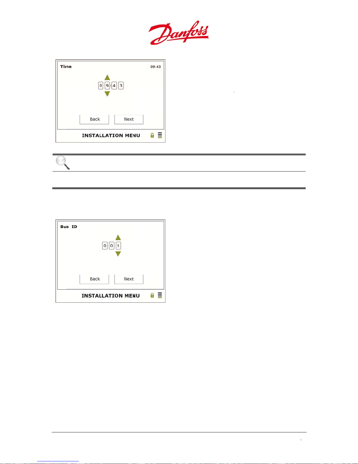
4. Ti
m
t
4
w
m
C
T
m
a
i
e
u
u
e
u
e
r
I
n
–
t
r
–
t
r
–
n
–
–
B
–
–
S
d
e
i
n
e
I
t
o
f
0
r
f
e
HH.M
M (24 H)
Ente
– Call up the
Up –
ncrease pres
Dow
– Decrease p
Left
Select previo
Righ
– Select next
Ente
– Confirm
Back
Left
Righ
– Next
Ente
– Confirm
ate
nt digit
resent digit
us digit
digit
5. Se
If RS
this
com
NOTI
he ti
data m
Bus ID
85 commun
ill be requir
unication is
E
e setting m
y be overwr
cation is use
d to be set
not used, th
st match th
itten!
d, set a uniq
nder Setup
is step can b
time on the
Enter
Up – I
Down
Enter
Left –
Right
Enter
e bus ID for
Network
missed.
actual instal
Call up the d
crease prese
Decrease pr
Confirm
ack
Next
Confirm
the inverter.
etup > Bus
lation site; o
igits
t digit
sent digit
For any foll
D (RS485). I
herwise
wer inverte
RS485
s,
48
U
ser Guide DLX UL
series L00410625-
01
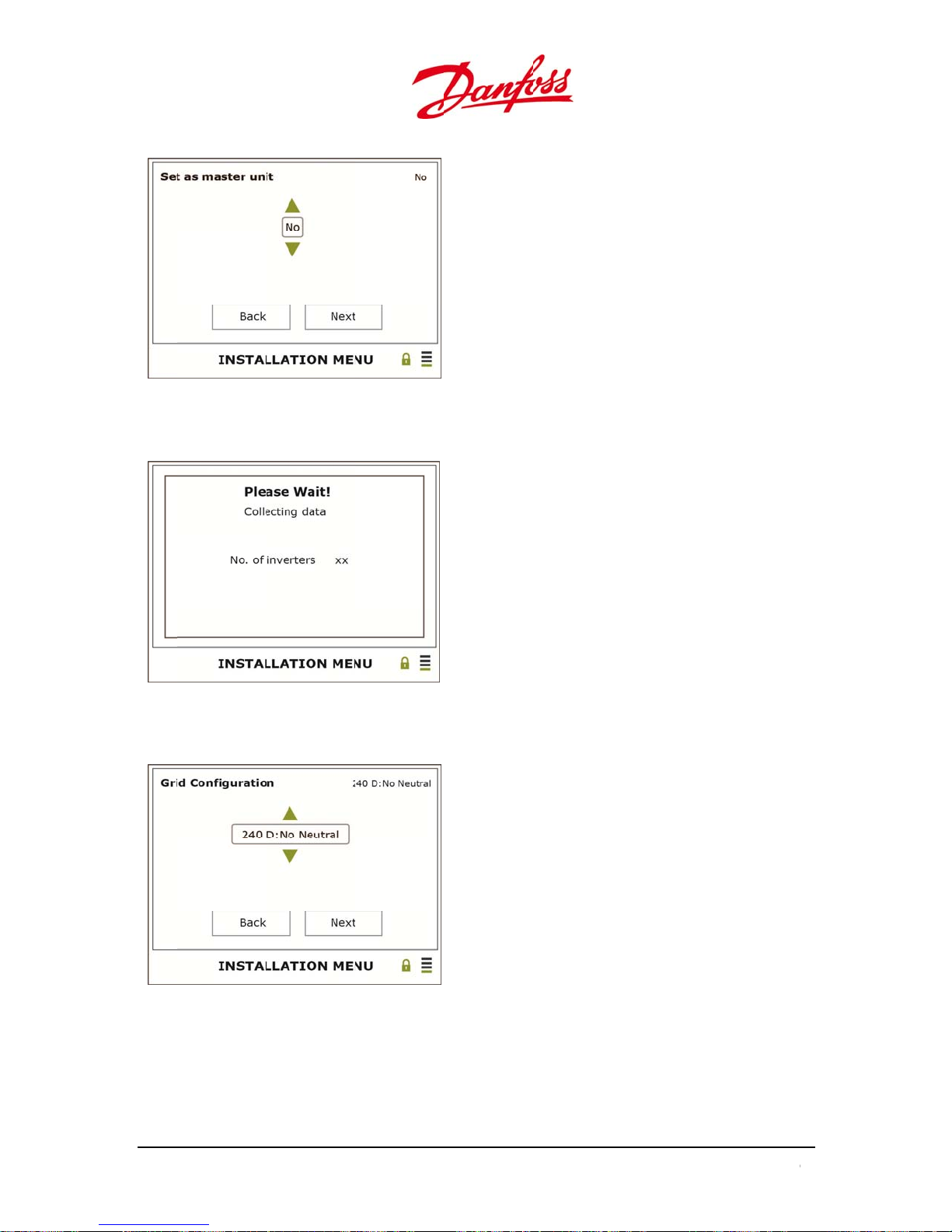
u
t
i
U
e
p
a
d
u
r
Y
n
r
–
t
r
o
r
r
a
p
2
D
r
–
t
r
o
w
c
s
o
8
o
n
t
D
e
4
:
6. Se
If the
scree
as Master
inverter is s
n will be dis
nit
t to master,
layed:
ata must be
Defa
Ente
Up –
Dow
Ente
Left
Righ
Ente
collected fr
lt – No
– Call up the
es
– No
– Confirm
Back
– Next
– Confirm
m the follo
ptions
er inverters.
The followin
g
7. Gr
d Configur
tion
Ente
– Call up the
Up o
Down – Sele
actu
l installation
120s
l/st., 240 D: C
08
: 120 WYE, 20
Ente
– Confirm
Back
Left
Righ
– Next
Ente
– Confirm
list of grid co
t the grid set
ite: 240 D: No
rner gr., 208
D: Corner gr;
figurations
ing of the
neutral, 240 D
: No Neutral,
tc.
User G
ide DLX UL series
L00410625-01
9
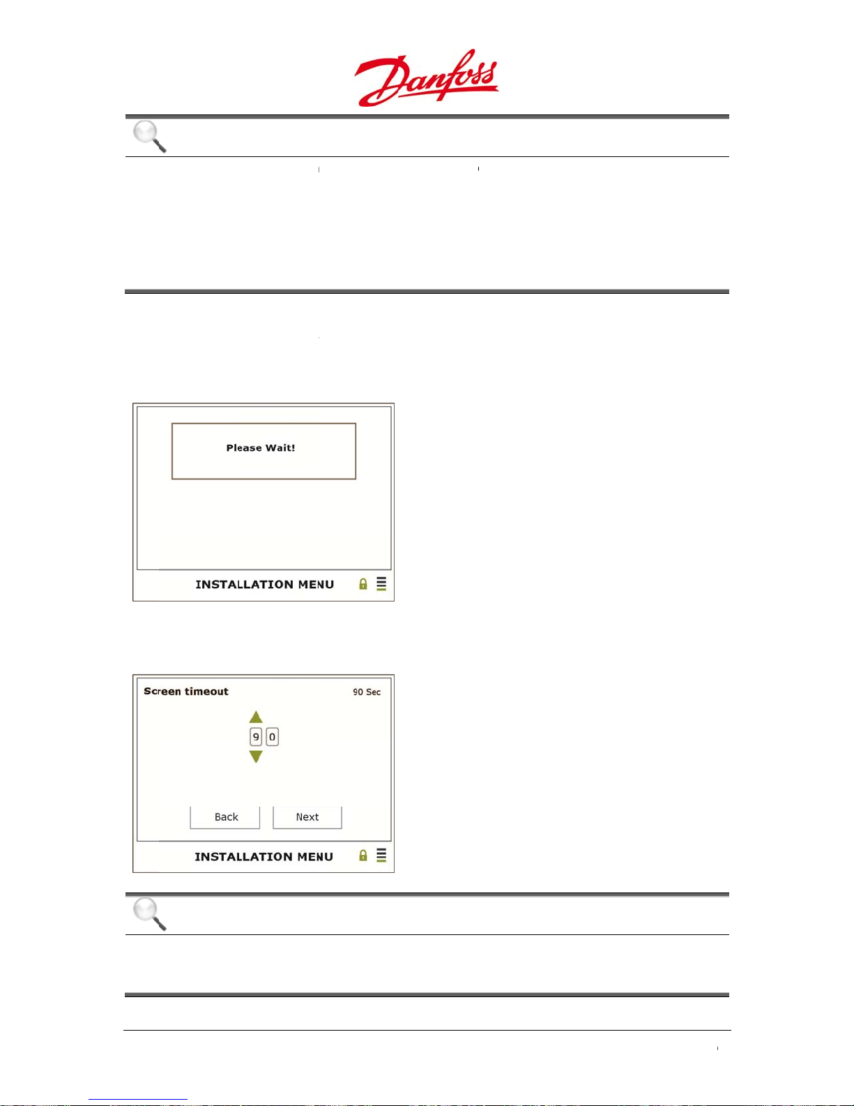
T
o
C
r
C
s
e
a
T
e
a
e
i
u
C
w
a
m
w
i
c
w
e
e
y
o
h
u
l
y
n
t
u
e
h
e
g
d
D
h
b
s
r
u
–
t
r
a
b
h
D
t
e
p
d
u
e
a
s
O
e
0
he f
Grid
NOTI
•
An in
Own
only
instal
•
he s
other
feder
llowing scr
ode Select
E
tallation ti
password)
ccessible us
lers and grid
lected grid
ise the inv
l electrical r
en is displa
on
er ensures t
ithin 5 ho
ng the Insta
operators b
onfiguratio
rter may no
gulations d
ed while inv
at the grid s
rs of feedin
ler passwor
contacting
must matc
operate or
e to incorre
rter setting
ettings can
power to t
, which may
anfoss.
that on the
e complian
ct limit valu
are being u
e changed (
e grid. Ther
only be obt
actual instal
to relevant
s.
dated:
sing the
after it is
ined for
lation site;
tate and
8. Sc
een Timeo
NOTI
The lo
Setting
ON at
t
E
est value all
the value to
ll times.
wed to be s
0 disables t
Ente
Defa
sec
Left
Righ
Ente
et is 30 sec,
e screen tim
– Call up the
lt – Screen ba
Back
– Next
– Confirm
nd the high
eout and lea
igits
cklight turns
est is 99 sec.
ves the scre
FF after 60
n backlight
50
U
ser Guide DLX UL
series L00410625-
01
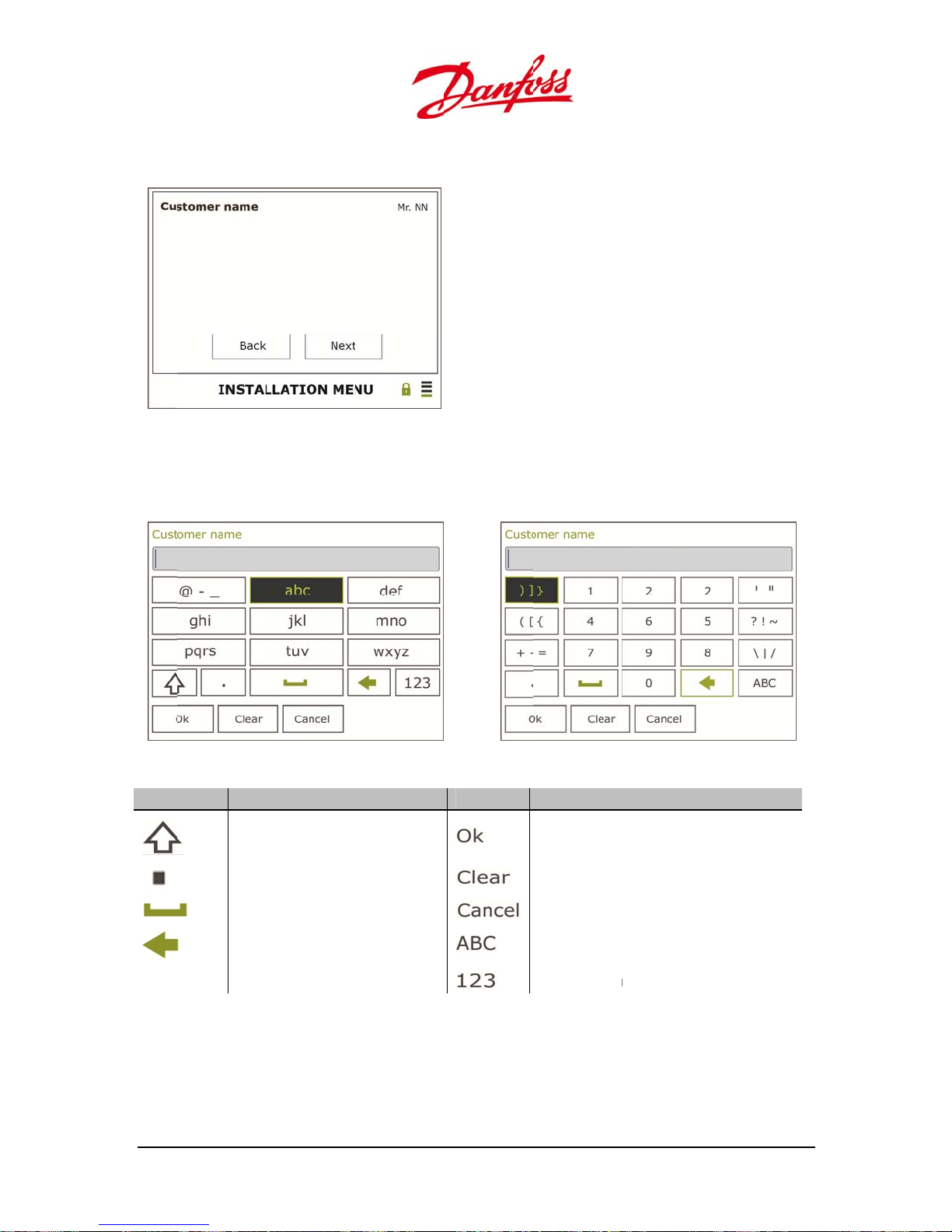
u
m
t
5
b
e
The
m
b
d
m
c
e
t
c
c
r
n
w
m
s
y
a
w
o
t
e
a
h
e
r
e
–
t
r
m
r
s
e
t
k
b
t
n
n
i
m
h
e
t
a
r
h
.
t
9. Cu
In so
Let
stomer Na
e of the su
er keyboar
e
menus the
ettings mus
Ente
The k
Left
Righ
Ente
be typed us
Nu
– Call up the
eyboard ena
Back
– Next
– Confirm
ing the func
ber keyboa
keyboard
les typing a t
ion keys:
rd
xt entry.
Table
.3: Available sy
Sym
ol Des
•
Ent
must be p
•
It is
possible to
the
text windo
•
re is a maxi
User G
ide DLX UL series
bols in the ke
ription
Upp
r- or lower-c
Poin
e
Spa
Can
el last letter
essed until t
avigate bet
, then using
um space f
L00410625-01
board
se letter
he wanted l
een the ch
Left and Rig
r 19 charact
Symbol
tter/numbe
racters by u
to navigat
rs in the tex
Descriptio
Confirm cha
Clear the typ
Go back with
Go to the Let
Go to the Nu
/symbol is s
ing the Up a
between th
window.
ges and exit
ing field
out saving ch
ter keyboard
mber keyboa
own.
rrow to set t
e characters
he menu
nges
d
e marker in
o
5
1
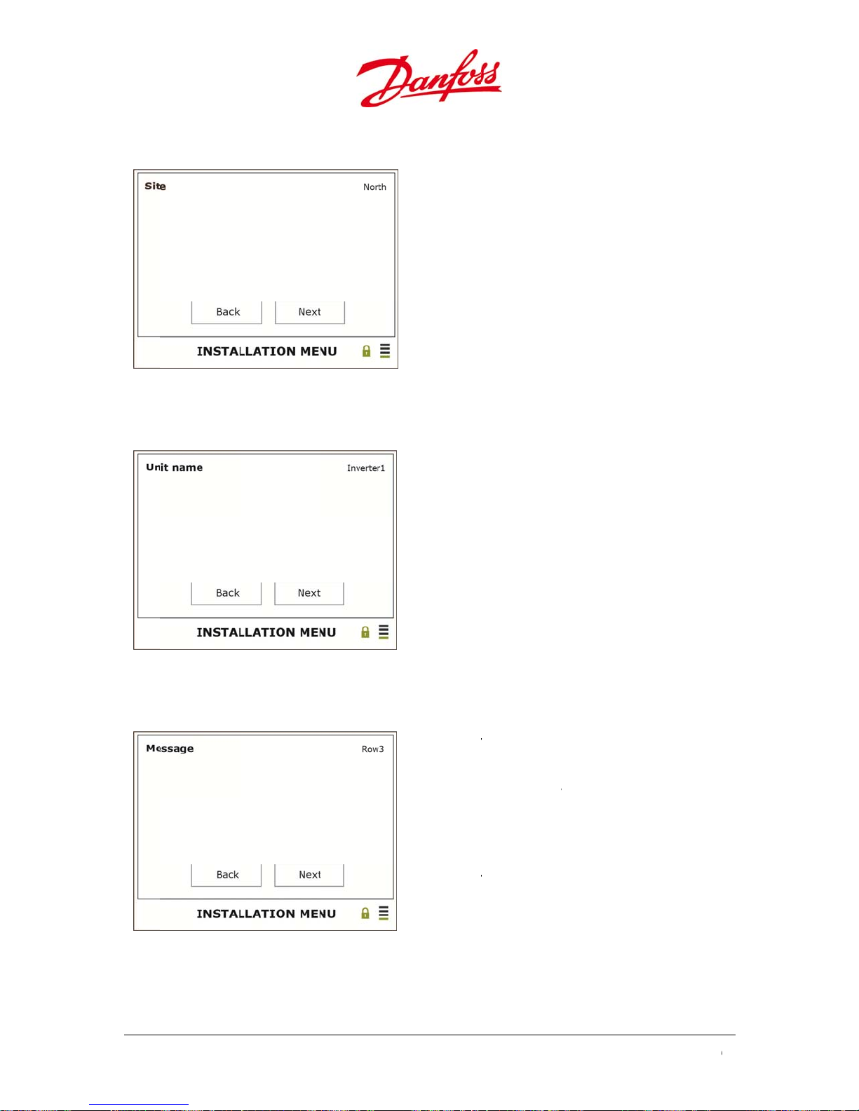
i
M
r
T
e
–
t
r
r
u
t
–
t
r
r
T
m
i
–
t
r
k
b
p
v
k
v
a
s
n
g
0
10. S
11. U
te
nit Name
Ente
– Call up the
he k
eyboard ena
Left
Back
Righ
– Next
Ente
– Confirm
Ente
The
iden
ify specific in
Left
Righ
Ente
– Call up the
nit name hel
Back
– Next
– Confirm
eyboard
les typing of
keyboard
s to distingui
erter in a larg
site name.
sh and
er plant.
12.
52
essage
Ente
his
ident
other
Left
Righ
Ente
– Call up the
essage field i
fy specific in
information.
Back
– Next
– Confirm
keyboard
s to help disti
erters in a lar
U
ser Guide DLX UL
guish and
er plant, or
series L00410625-
01

u
O
a
n
e
r
h
e
w
C
e
k
h
e
u
e
o
m
l
y
a
y
i
n
C
s
c
o
t
t
e
d
n
y
h
y
m
d
u
l
t
w
r
u
g
C
T
p
t
o
–
t
r
r
e
t
h
e
4
n
b
c
s
r
u
d
o
o
3
e
D
t
0
s
g
k
n
f
o
c
d
C
e
o
s
t
s
f
t
13.
wner Pass
ord
Ente
Defa
Chan
NOTI
his
inver
revisi
Left
Righ
Ente
– Call up the
lt – 0003.
e the passw
E
assword is n
ers on the CA
ns below v1.
Back
– Finish
– Confirm
igits
rd to 4 optio
t transmitted
N bus on GUI
2.
al digits
to other
irmware
A ‘W
War
NOTI
With se
carried
•
Look
instal
and r
•
Chec
switc
great
•
If the
are f
for fe
rning’ box is
ing Box
E
veral inverte
out correctl
t the displa
lation menu
d LEDs are l
that the co
es are ON, t
r than 7 W
Start Up pha
lly automati
ding power
displayed if
rs connecte
on all the fo
ed menu a
is still displa
t.
nection of t
hat the volta
of power.
D
e is correctl
during nor
into the gri
an error occ
it must be c
llowe
invert
d the LEDs: I
ed and/or t
e CAN cabl
ges are >18
carried out
al operatio
.
rred during
Possi
1. No
2. Wro
hecked that
rs.
t is not carri
e green LE
s are correc
VAC and 23
the inverter
, and no Gu
installation:
le errors:
ommunicatio
ng grid settin
the installati
d out corre
is not lit an
, that the A
VDC and th
are ready t
ide control i
n
s
n is been
tly if the
the yellow
and DC
re is a
use. They
necessary
•
Ch
ck the LEDs
cor
ectly perfor
•
If t
e Start Insta
inv
rter.
User G
ide DLX UL series
n the inver
ed and tha
lation - scre
L00410625-01
ers. If the ye
the grid set
n is still sho
low and red
ings are cor
n, run thro
are lit chec
ectly set.
gh the instal
that the ins
lation proce
allation is
s on the
5
3

O
6.
T
c
a
e
e
T
e
6
s
sOwn
a
e
A
r
t
.
s
c
c
e
d
d
d
e
d
f
C
a
c
e
t
N
m
a
s
o
c
d
r
l
c
n
a
n
w
d
m
b
c
s
n
u
0
w
e
e
e
o
a
h
u
e
e
s
n
u
o
c
e
n
(
a
n
l
e
e
o
a
r
0
c
e
e
a
w
s
t
e
o
n
w
f
0
e
a
r
his
with
Pleas
color
PER
hapter desc
PC connec
refer to 5.1
d LEDs
TIO
ibes how to
ed to the e
2. User Interf
operate the
bedded we
ce for a des
enus in th
server.
ription of th
LCD screen
e LCD Scree
with the fun
and the m
tion keys or
anings of th
6.1.1
her
Table
Pas
Gue
Inst
Acce
.
are three a
.1: Password ac
word Acc
t
er
ller
Rea
Rea
The
to: S
If th
Rea
the i
Dan
NOTI
Any ch
modifi
level.
s Level
cess levels t
ess levels
ss
only access t
and write ac
efault Owne
etup>Genera
password is
and write ac
nverter serial
oss to obtain
E
nge of setti
ations must
and Pa
the differe
o all values.
ess to all val
password is
l Setup>Pass
ost or forgott
ess to all lev
umber. If th
new passw
g needs a p
be done wit
swords
t submenus:
es and set lev
003. This pas
ord.
n, please co
ls and set val
password is l
rd. It will requ
ssword. On
in 1 minut
els except the
word can be
tact Danfoss t
es. The Instal
st or forgott
ire the invert
e the passw
before the
installer relat
changed by n
o obtain a ne
er password i
n, please con
r serial numb
rd has bee
ccess resets
d values.
vigating
password.
based on
act
r.
entered,
to Guest
6.1.2
.
Hom
scree
n timeout in
OFF).
If the
plant
.
54
Hom
is the stand
unit is set as
ard display,
erval, which
master, the
hich is alwa
is set during
efault men
ys shown if
installation
contains st
o buttons a
minimum 3
tus/mode in
e touched
sec, maxim
formation o
U
ser Guide DLX UL
ithin the
um 99 sec, o
the whole
series L00410625-
01
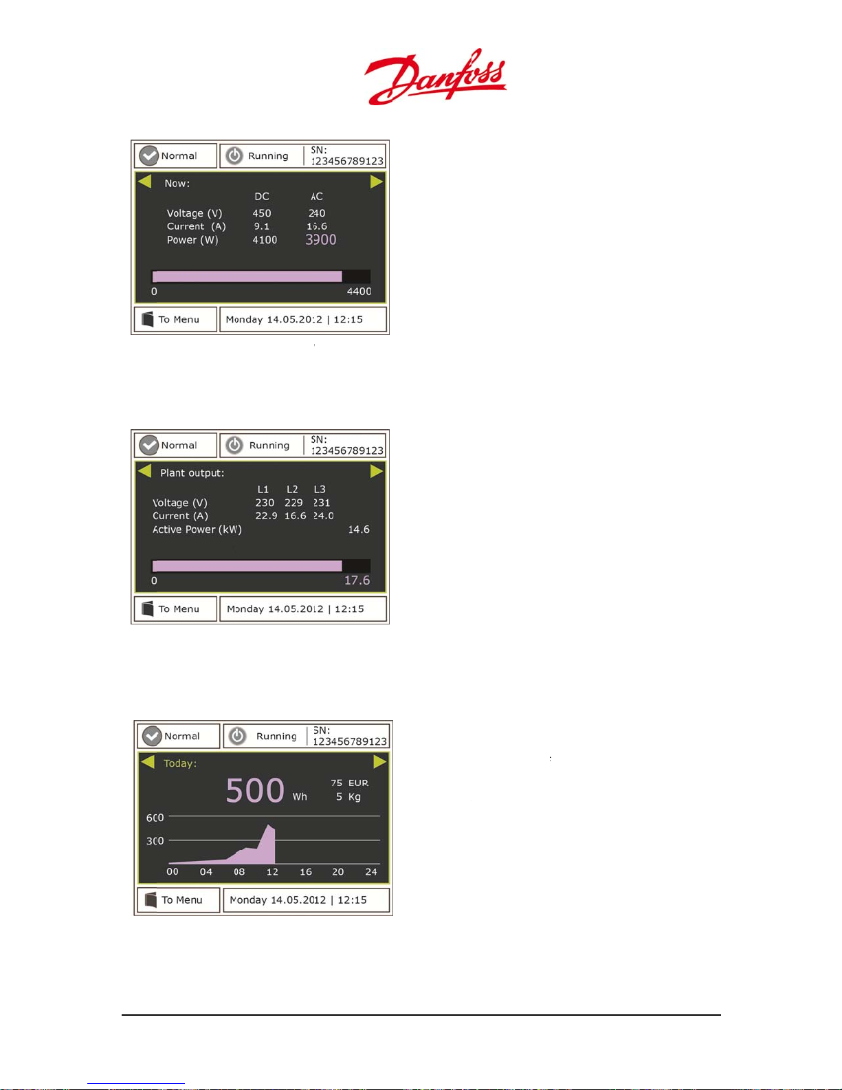
u
l
h
e
d
e
d
s
e
r
g
d
t
t
l
e
t
e
e
w
D
e
g
i
d
d
u
(
u
a
r
h
h
s
m
o
-
p
e
m
c
Singl
e Inverter
Figur
PV P
6.1: Standard
ant
isplay for a sin
le inverter
Values
voltag
instan
graph.
Plant
curr
num
sho
of PV (DC) an
and power a
aneous outp
values of PV
nt, voltage an
rically. The c
n as a bar gra
feed-in (AC)
re shown nu
t power is sh
DC) and feed
d power are s
rrent output
ph.
current,
erically. The
wn as a bar
in (AC)
hown
ower is
Figur
Use t
Figur
User G
6.2: Standard
e scroll key
6.3: Energy ha
ide DLX UL series
isplay for a larg
to observe
vest throughou
L00410625-01
er PV plan
aily, month
the day
y and yearly
Up or
Left or
total y
•
Ener
•
Peak
•
Earn
•
Avoi
values:
own – Navig
Right – Obse
arly values of
y harvest [W
power [Wp]
ng [value of t
ed CO2 emis
te in the scre
ve the daily,
:
/kWh]
e respective
ion [kg].
n.
onthly and
ountry]
5
5
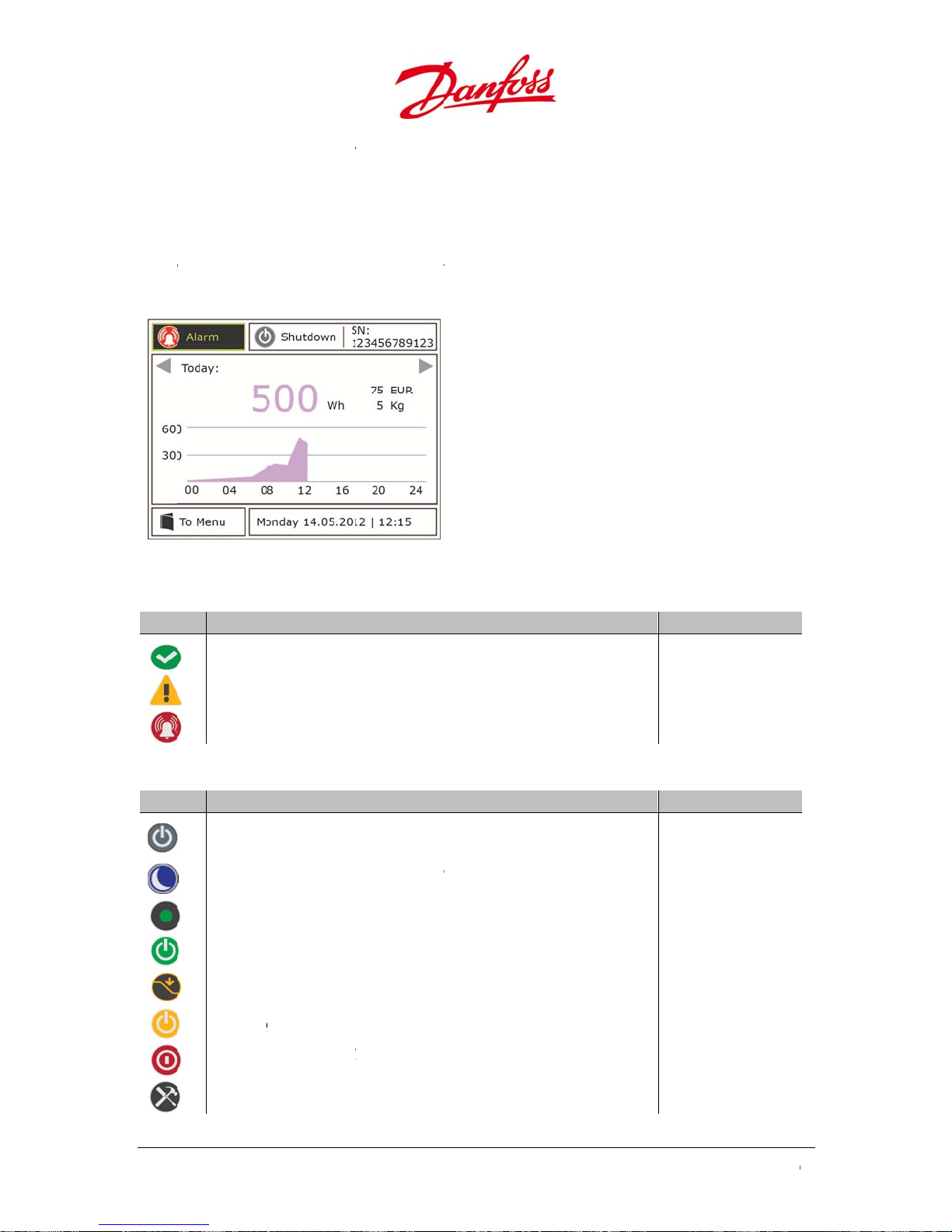
2
e
s
m
e
r
u
6
n
6
n
e
s
o
e
p
u
g
d
u
y
p
g
n
g
w
o
y
t
e
e
h
r
l
o
g
s
n
g
w
r
y
e
v
c
m
r
w
t
i
p
d
w
y
o
d
t
o
t
r
r
a
r
e
o
o
e
p
n
o
o
o
a
o
d
u
r
w
w
w
w
0
6.1.
The l
statu
The
mod
The
ight section
prod
Figur
Table
.2: Inverter stat
Sig
.1. Upp
ft section s
options. It i
iddle secti
s options.
ct label.
6.4: Upper dis
Status
r Displa
hows the sta
also a shor
n shows th
shows the s
lay area of the
s
Area
tus of the in
cut to the A
operation
rial numbe
ome screen
erter. Refer
tive Alarms.
ode. Refer t
of the inver
Up o
Ente
o Table 6.2 f
Table 6.3 f
er, which is
Down – Navi
– Confirm
r the three
r the eight d
lso to be fo
gate in the sc
LEDS
ifferent
ifferent
nd on the
een.
Table
Sig
Normal
Warnin
Alarm: i
.3: Inverter mo
Mode
Off: Inp
circuitr
Sleepin
start up
Start-U
Runnin
De-rati
overhea
Shuttin
Shutdo
conditi
Service
inverter ope
: inverter stil
nverter in shu
e
t power is n
: automatic
: initializatio
: grid feedin
g: output po
ting
Down: inve
n: inverter/s
ns
Mode: invert
ates with no
operates, bu
tdown, there
t sufficient to
hutdown. In
of input valu
er is reduce
ter in shutdo
stem failure
r can be Gui
arnings or al
there is a wa
s an alarm
start the pow
ut power is n
es and grid c
to protect th
n mode
r unstable o
ely overridde
rms
ning
r control
t sufficient t
nditions
e inverter aga
erational
inst
Green
Green
Red
LEDs
Yello
Yello
Green
Green
Green
Yello
Red
Yello
& Yellow
& Yellow
& Yellow
56
U
ser Guide DLX UL
series L00410625-
01

u
2
T
o
s
e
3
e
e
e
p
e
v
n
y
h
e
m
a
e
e
e
t
v
r
m
r
u
r
h
g
b
t
a
e
A
m
a
b
.
6.1.
he l
Figur
6.1.3
Statu
are r
.2. Low
wer section
6.5: Lower dis
Statu
.
displays th
ad-only.
r Displa
contains a s
lay area of hom
s
operating
Area
ortcut to th
screen
ode and sta
Main Menu
Up or
Enter
tus of the in
and shows t
Down – Navi
– Confirm
erter and th
he current d
ate in the scr
e PV plant.
te and time
en.
ll the values
6.1.
Activ
signs
Figure 6.6:
.1. Acti
Alarms disp
appearing i
Submenus of St
e Alarms
lays detailed
the upper l
tus
information
ft corner of
Up o
sub
Ente
about the c
he Home sc
Down – Navi
enus
– Select a su
rrent opera
een. Refer al
gate through
menu/confir
ing mode -
so to 7.2. Ta
the
nd status
le of Events.
User G
ide DLX UL series
L00410625-01
5
7
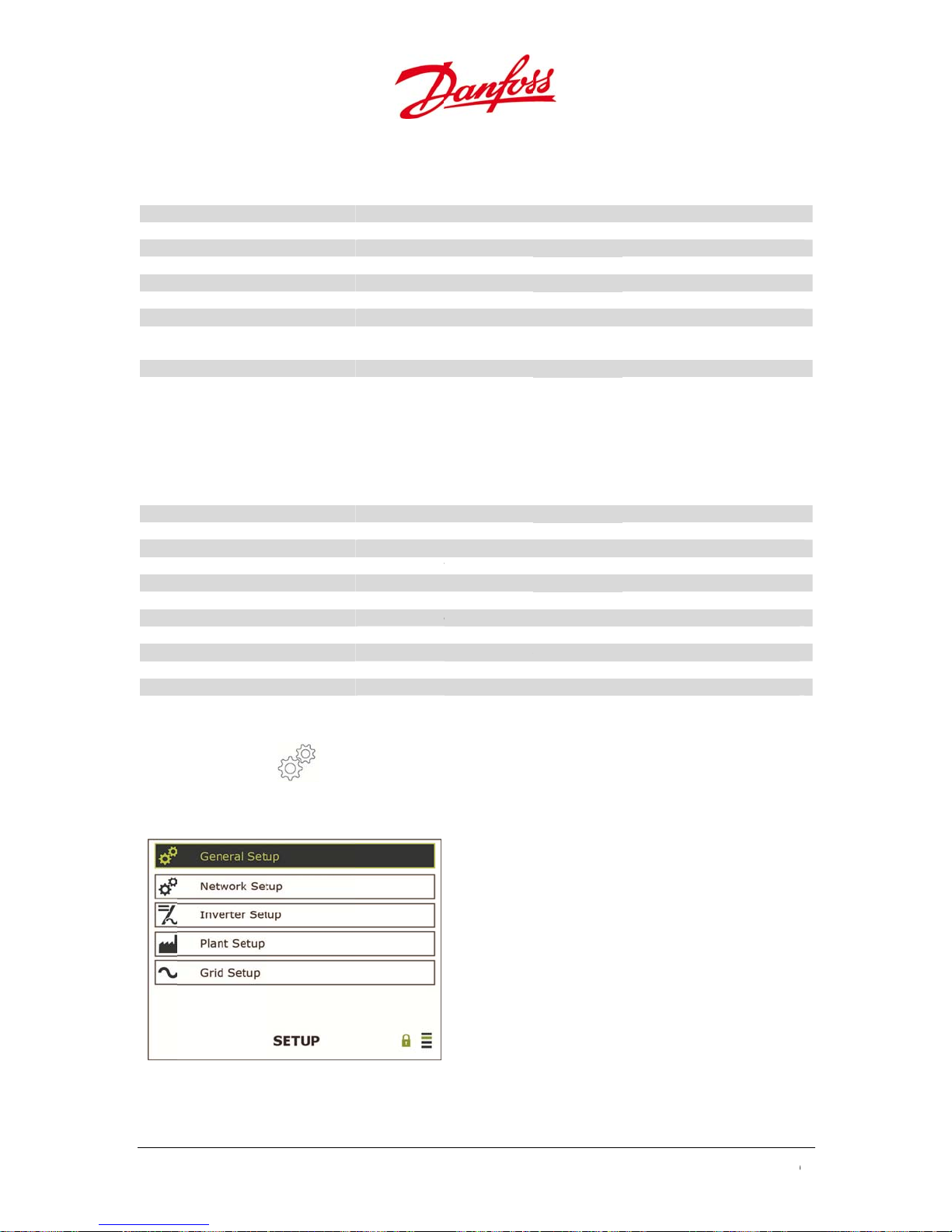
3
t
e
r
t
p
r
g
p
r
3
e
r
t
t
p
p
p
g
p
r
p
t
s
e
e
t
v
r
n
g
t
t
o
p
t
S
s
e
t
e
t
t
e
T
T
T
a
T
n
u
T
u
t
T
o
v
n
s
T
o
T
o
u
o
o
T
r
n
o
o
d
o
e
w
n
e
o
h
v
o
u
d
d
g
D
–
a
r
m
o
A
n
e
m
s
a
r
e
r
e
e
f
P
a
m
t
n
t
e
u
h
0
6.1.
Inver
Mod
Erro
Inpu
Out
Inve
Ener
Tem
Isola
Ope
6.1.
Plant
there
Mod
Erro
Num
Num
Num
Num
Inpu
Inpu
Out
Out
Out
Ener
.2. Inve
er Status dis
Parameters
ut Parameter
ter Peak Pow
y Today
erature
tion Resistanc
ating Hours
.3. Plan
Status displa
are other in
ber of inverte
ber of active i
ber of alarms
ber of warnin
Current
Power
ut Current
ut Voltage
ut Power
y produced t
ter Statu
lays the op
r
Status
ys the opera
erters conn
s
verters
s
day
rating mod
he inverter ha
he inverter ha
Current, voltag
Current, voltag
Highest power
otal energy h
emperature i
Level for a safe
equipment fail
otal inverter r
ing mode, s
cted, and th
The inverter ha
The inverter ha
otal number
Number of acti
Event alarms i
Event warning
otal current fr
otal power fr
Total feed-in c
Total feed-in v
Total feed-in p
otal energy p
, status and
s 8 different m
s 3 different sta
e and power fe
e, frequency an
achieved throu
rvest through
side the invert
insulation bet
re. The resista
nning time fro
atus and op
e inverter ha
s 8 different m
s 3 different sta
f inverters in t
e inverters in t
the plant
in the plant
m the PV mod
m the PV mod
rrent to the gri
ltage to the gri
wer to the gri
oduction throu
perating pa
des. Refer to T
tus levels. Refe
from the PV
d power fed fr
ghout the day
ut the day
r
een DC - and
ce must be mi
m Start Up
rating para
s been set a
des. Refer to T
tus levels. Refe
e plant
he plant
ules to the inv
les to the inve
d from all activ
d from all activ
from all active
ghout the day
rameters of
ble 6.3
to Table 6.2
odules to the i
m the inverter
C side to preve
imum 600 kΩ
eters of th
the master
ble 6.3
to Table 6.2
rters
ters
inverters
inverters
inverters
or the plant
he inverter.
verter
o the grid
nt injury or
PV plant, if
nit.
6.1.4
Setu
Setu
.
displays set
ings and da
Figure 6.7:
ubmenus of Se
58
a from the i
up
verter, the
Up or
Enter
rid and the
own – Navig
Select a sub
V plant.
te through t
enu/confirm
U
ser Guide DLX UL
e submenus
series L00410625-
01
u
4
r
g
g
e
w
R
i
i
e
e
4
o
O
w
w
w
8
8
a
e
p
e
n
w
p
o
C
d
h
s
a
p
f
s
p
t
6
t
d
s
k
T
a
m
m
r
c
n
i
e
c
v
r
h
h
T
d
T
d
o
T
d
o
b
n
n
d
e
e
g
N
n
y
e
v
e
h
e
P
n
u
t
t
e
u
o
e
s
W
y
e
c
C
y
n
n
S
t
d
d
A
w
b
O
e
c
i
g
[
d
b
f
h
6.1.
Gene
chan
Lan
Date
Tim
Pass
CO2
Earn
Earn
Scre
Pow
time
6.1.
Netw
the
Net
[Stat
Net
Net
DNS
Bus I
RS4
RS4
Bus I
Set
.1. Gen
al Setup dis
ed using th
uage
ord
ate
ngs Rate
ngs Currency
n Timeout
r Saving duri
.2. Net
rk Setup dis
wner passw
NOTI
All IP a
range t
ork IP-Addres
ic/DHCP]
ork Subnet M
ork Gateway
IP
D (RS-485)
5 bitrate
5 parity
D (CAN)
s Master unit
ral Setu
lays some o
Owner pas
g night
ork Setu
lays the set
rd. Refer to
E
dresses rela
at is allowe
s
the general
word.
he preferred l
Spanish, etc
Current date
Current time
Owner passwo
CO2 emissions
Feed-in tariff i
Valid currency
ON time for th
Power saving c
option turns th
night time, to s
ings for the
.2 Connectio
ed to the in
by the loca
Unique netwo
Indicates whet
Determines w
Network point
he DNS IP ad
he inverter’s i
Measurement
Error detecting
set of bits with
he inverter’s i
Several inverte
system, must h
inverters.
parameters
nguage must
ust be set duri
ust be set duri
d must have 4
onserved, bas
the respective
n the respectiv
display backli
an either be O
e GUI off 15 mi
ave power. Onl
onnected n
n between In
erter and w
l network.
k address for t
er the IP addr
at subnet the I
acting as entra
ress
entification n
f data transmi
code: A bit tha
value one. Sel
entification n
rs connected t
ave one master
f the invert
e set during in
g installation
g installation
igits. Default i
d on 0.7 kg/k
country
e country
ht
or OFF during
utes after the i
applicable for
twork, whi
erter and P
b must be c
e inverter
ss is static or d
-address belo
ce to another
mber on the R
ted in a given a
ensures an od
ction: None, O
mber on the C
gether in a po
inverter and th
r, which can
stallation: Engli
0003
h
nighttime. Ena
nverter enters
follower invert
h can all be
.
onfigured w
namically assi
gs to
etwork
-485 bus
mount of time
or even num
d, or Even
N bus
er control and
e rest must be
all be
sh [default],
ling this
FF mode, ie.
rs
hanged wit
thin the
ned
[bps]
er of bits in a
monitoring
ollower
User G
ide DLX UL series
L00410625-01
5
9

4
t
e
e
a
P
R
S
S
H
H
t
t
n
n
=
=
=
4
e
o
a
i
p
s
4
G
g
s
a
r
p
a
N
s
s
o
a
n
r
B
t
y
S
p
5
s
y
p
o
o
d
t
e
t
a
n
a
w
w
f
n
v
T
w
w
o
e
T
/
o
o
n
T
a
s
t
o
w
g
f
a
n
d
s
o
d
a
b
b
t
e
e
e
t
a
s
o
t
e
n
e
u
o
i
u
f
a
a
t
a
n
r
n
c
o
’
t
w
b
e
r
n
o
n
a
d
f
t
n
f
t
0
f
6.1.
Inver
proc
Mod
Seri
DLX
DLX
GUI
GUI
GUI
GUI
SW1
Part No.
SW1
Revision
Con
rol Board Part
rol Board Revi
Con
Mai
Mai
SW2
Part No.
SW2
Revision
1. GUI
2. DSP
3. PCB
.3. Inve
er Setup dis
ss, and is re
l
l Number
art No.
evision
oftware Part
oftware Revis
ardware Part
ardware Revi
Board Part N
Board Hardw
Graphical User I
Digital Signal P
Printed Circuit
ter Setu
lays the vari
d-only.
o.
ion
No.
ion
No.
ion
.
re Rev.
terface, which al
ocessing, which i
oard, which host
us data for
Inverter model
Unique identifi
Identifier for e
Unique versio
inverter revisio
The GUI1 softw
Revision numb
Identifier for th
Revision numb
The DSP12 soft
Revision numb
DSP-card hard
Version name
Identifier for th
Unique revisio
main board re
he DSP2 soft
Revision numb
lows interaction
s a microprocess
s all the compon
he specific i
er for each inve
ch inverter har
name for keep
n within Danfo
re part numbe
er for the GUI s
e GUI-card har
er for the GUI h
are part num
er for the DSP1
are part num
or the DSP con
e PCB3 hardwar
number for k
isions
are part numb
er for the DSP2
ith the inverter
r controlling the
nts and subsyste
verter set d
rter. Also to be
ware configur
ing track of the
s
r.
ftware
ware
ardware
er.
software
er
rol card hardw
e.
eping track of
r
software
hrough the displ
power conversio
ms of the inverte
ring the ma
found on the p
tion within Da
development
re
he developme
y.
in the inverter.
.
nufacturer
oduct label
foss
f different
t of different
6.1.
Plant
Own
Cust
Site
Inst
Serv
Res
Unit
Mes
6.1.
The
chan
acce
cont
Grid
Grid
Grid
Grid
.4. Plan
Setup displa
password.
mer Name
llation Date
ce Date
onsible
Name
age
.5. Grid
rid Setup dis
ed within
sible by usin
cting Danfo
code
nom voltage
nom frequenc
Setup
s useful inf
etup
lays the gri
hours after
g the Install
s.
rmation abo
he customer
The site name
May be used f
May be used f
Field for keepi
his text string
An extra mess
settings ba
he installati
password,
AC grid confi
Additional in
Nominal volt
Nominal freq
ut the PV pl
owner name
r setting the in
r setting the m
g a note of the
is displayed in
ge field for add
ed on the s
n using the
hich will o
uration, e.g. D
ormation abo
ge of the grid
uency of the gr
nt, which ca
tall date
st recent servi
company/pers
he master unit
itional notes
lected coun
Owner pass
ly be availa
elta Split-phas
t the valid grid
n site
id on site
be change
e date
n responsible
s list of connec
ry. The setti
ord. Therea
le to the ins
, Stinger etc.
protection stan
using the
or service
ed inverters
gs can be
ter it is only
aller by
dard
60
U
ser Guide DLX UL
series L00410625-
01

u
T
y
l
V
6
p
h
h
V
6
p
h
h
e
6
p
h
r
d
a
a
T
e
o
t
i
o
o
t
i
e
p
p
y
g
o
2
M185
6
0
0
0
M213
224
4
e
i
M59.
d
e
s
2
2
2
4
2
2
6
8
i
6
s
s
g
e
t
T
i
e
e
d
e
r
r
r
h
n
e
e
h
h
9
1
9
1
u
9
1
9
1
p
e
e
Adjustable
Field
he s
Insta
ler password
1. Vo
ltage
208
Table
.4: Adjustable v
Tri
Limits
Low
Low
Hig
Hig
240
Table
.5: Adjustable v
Tri
Limits
Low
Low
Hig
Hig
stem install
AC Delta: N
limit
and fast limi
limit
and fast lim
Delta: N
AC
limit
and fast limi
limit
and fast lim
rip Limits
r may chan
is needed t
o Neutral, 1
ltage trip limits
Trip
t
10
Neutral, 12
ltage trip limits
Trip
t
12
e the grid s
change the
0 WYE, Corn
for 208 V
Voltage
in
.5 V
AC
.5 V
AC
2
8 V
AC
8 V
2
AC
Split-phase,
for 240 V
Voltage
in
.7 V
AC
.5 V
AC
0 V
AC
0 V
2
AC
AC
2
2
120 Stinger,
AC
2
2
ttings accor
e settings.
r Grounded
Max
08 V
AC
08 V
AC
6.3 V
AC
7.1 V
AC
Max
40 V
AC
40 V
AC
1.5 V
AC
5.5 V
AC
ding to elect
T
rip Time
Min
50 ms
50 ms
50 ms
50 ms
Corner Gro
T
rip Time
Min
50 ms
50 ms
50 ms
50 ms
rical regulati
Max
50 ms
20 ms
50 ms
20 ms
nded
Max
50 ms
20 ms
50 ms
20 ms
ons. The
2. Fr
Table
Tri
Low
Hig
ral Grid Setu
Gene
Gene
Grid
code
Desc
ription
Grid
nom voltage
Grid
nom frequenc
Grid
configuration
Fee
ing phase
Volt
Volt
User G
quency
.6: Adjustable fr
Limits
limit
limit
al Grid Setu
ge limit min
ge limit max
ide DLX UL series
quency trip lim
Trip
displays gri
L00410625-01
ts
Frequency
in
35 Hz
60
. 0 Hz 6
parameter
Grid code of in
Name of the gr
Nominal volta
Nominal frequ
Grid configura
he phase the
Lower disconn
Upper disconn
Max
0.0 Hz
0.45 Hz
related to t
tallation
id protection st
e of the grid o
ncy of the grid
ion of the site:
nverter is conn
ction limit of t
ction limit of t
T
rip Time
Min
50 ms
50 ms
e selected g
andard
site
on site
.g. Delta Split-
cted to:
e grid voltage
e grid voltage
Max
80 ms
80 ms
rid.
hase, Stinger
on site
on site
tc
6
1
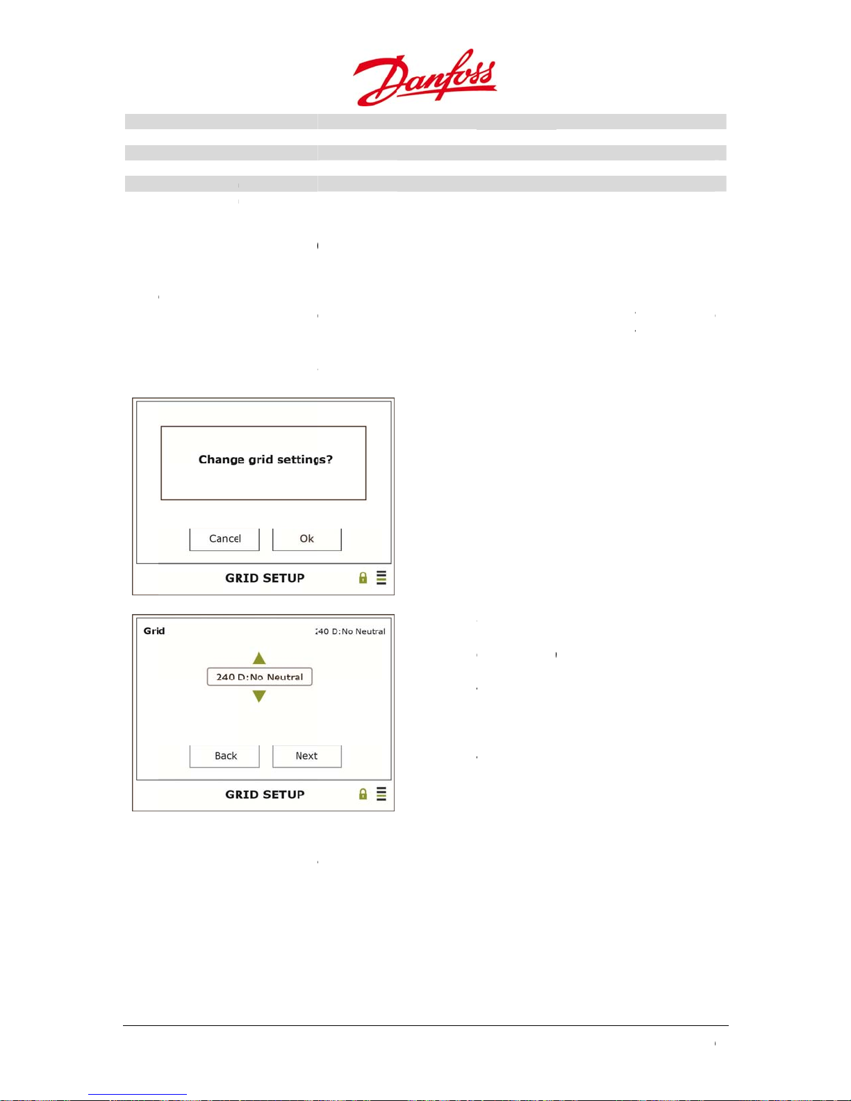
Volt
a
a
u
u
u
u
4
m
e
e
t
The
e
m
m
n
M
er
.
h
g
G
>
o
t
e
e
a
e
o
o
e
e
o
o
i
i
o
g
h
e
a
c
l
h
h
l
r
t
a
o
s
c
2
W
r
–
t
r
c
I
b
a
c
e
0
:
r
w
y
l
v
1
a
:
.
0
w
b
.
Volt
Freq
Freq
Freq
Freq
ge time limits
ge time limits
ency limits m
ency limits m
ency time li
ency time li
min
max
in
ax
its min
its max
Minimum disc
Maximum disc
Lower disconn
Upper disconn
Minimum disc
Maximum disc
nnection time
nnection time
ction limit of t
ction limit of t
nnection time
nnection time
limit
limit
e grid frequen
e grid frequen
limit
limit
cy on site
cy on site
6.1.
•
Fro
•
Ent
•
Aft
d to change
use
ins
•
.6. Cha
the Main
– Confirm
r 5 hours of
allers and gr
question “C
ging the
enu: Setup
feeding in p
he grid cod
id operators
ange grid s
rid Sett
General Gr
wer to the
settings. T
only by cont
ttings?” app
ngs
d Setup > G
rid after ins
e Installer p
acting Danf
ars in the di
OK –
Can
Up or
settin
40 D
120
Ente
Left
Righ
Ente
id Code.
allation the
ssword is o
ss.
play.
Continue
el – The oper
Down – Sele
g: 240 D: No n
: Corner gr., 2
YE, and 208 D
– Confirm
Back
– Next
– Confirm
nstaller pass
tained for s
tion is cancel
t the respecti
utral, 240 D:
8 D: No Neutr
Corner gr; etc
ord must
stem
ed
e grid
20spl/st.,
l, 208 D:
e
•
Aft
r the grid se
newly confi
the
ttings are ch
ured grid s
62
nged, the s
ttings.
reen will ret
urn to the G
id Setup scre
U
ser Guide DLX UL
en, showing
series L00410625-
01

u
m
w
5
t
d
t
t
5
t
t
t
u
m
t
m
h
e
s
r
d
p
t
A
t
e
t
g
m
d
d
m
n
b
a
t
u
w
e
e
b
e
e
t
e
s
m
n
D
–
a
a
o
b
i
o
e
a
m
h
d
o
d
d
m
n
m
e
O
h
d
n
p
e
C
t
e
6.1.5
Com
pass
Figur
6.1.
Inver
provi
Dele
Dele
Rese
Com
.
ands give t
ord.
6.8: Submenu
.1. Inve
er Comman
e storage s
e Energy Log
e Data Log
Web Admin
ands
e ability to
to Commands
ter Com
s gives the
ace.
ccount
elete stored
ands
ability to d
Deletes the en
Deletes the 15
Resets the we
and Password t
data in the i
Up or
Enter
lete events
rgy log items a
minutes averag
administrator
o admin
verter logg
own – Navig
Select a sub
saved in t
nd summarize
e power values
ccount back t
r using the
te through t
enu/confirm
e inverter
values of the i
of the inverter
default. User is
wner
e list
ata logger
verter
set to admin
o
6.1.
Plant
inver
Dele
Dele
Rese
Reb
6.1.6
Alar
abou
requi
User G
.2. Plan
Commands
er to provid
e Energy Log
e Data Log
Number of In
ild plant ener
Alar
.
Setup enabl
energy pro
re use of the
ide DLX UL series
Comma
gives the a
storage sp
verters
y log
Setup
es configura
uction, stat
Owner pass
L00410625-01
ds
ility to del
ce.
Deletes the en
Deletes the 15
Update if inver
Rebuilds the pl
currently conn
several minute
ion of an e
s and opera
ord.
te events s
rgy log items a
minutes averag
ers are added
ant energy log
cted and runn
.
ail account,
tion mode t
ved in the
nd summarize
e power values
r removed fro
ased on the e
ng in the syste
so the invert
one or mor
ata logger
values of the
of the plant
the plant
ergy logs of th
. This process
er can send i
receivers.
of the mast
lant
inverters
may take
nformation
hanges
6
3
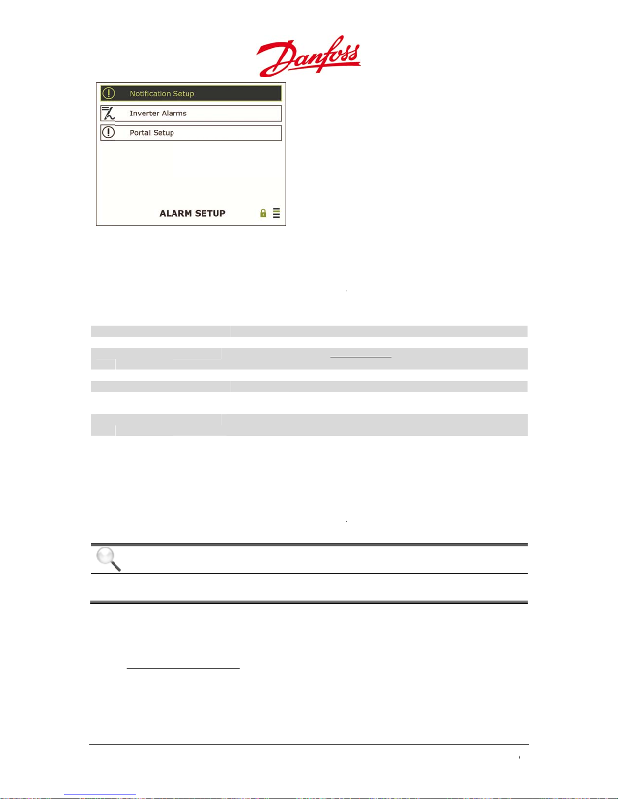
Figur
6
s
w
d
P
P
n
m
T
n
e
o
o
e
n
a
e
s
f
u
m
e
e
e
o
p
C
v
S
d
d
e
r
d
o
p
e
T
m
u
U
m
r
t
d
s
p
c
e
r
c
i
g
D
–
k
x
r
r
M
o
S
e
u
S
e
o
a
m
q
g
D
w
e
e
d
h
o
t
m
t
h
d
w
0
d
s
n
6.9: Submenu
to Alarm Setup
Up or
Enter
own – Navig
Select a sub
te through t
enu/confirm
e list
6.1.
In No
statu
User
Pass
Sen
Rece
Rece
SMT
SMT
E – M
To e
the
most
he i
.1. Noti
tification Set
on e-mail
Name
ord
er email addr
iver email 1
iver email 2
server
port 1
ail Set-up
able the inv
ails to the r
likely have t
verters sup
NOTI
If an in
same I
ication S
p paramete
ust be type
ss
rter to send
ceiver(s). M
use their in
ort unencry
E
erter is mov
P, a new SM
tup
s needed fo
in.
User name for
Digits, letters a
A valid email a
notifications
Mail address fo
Mail address fo
The IP address
be an IP addre
Sets the SMTP
0)
e-mail notifi
st companie
ternet servic
ted SMTP t
d, or conne
P server mu
the inverter
he mail server
d symbols ma
dress, e.g. xxx
r recipient 1
r recipient 2
of the SMTP se
s (ie. numeric)
ort number fo
ations an S
s have their
provider (I
affic on port
ted, to anot
st be assign
to send noti
ing up the use
@xxxxxx.xxx, re
ver for enablin
SMTP server.
TP server is
wn server,
P) mail serv
25.
her network
d.
fications ab
r password for
uired to be ab
delivery of e
efault is 25 (ini
required, w
hile normal
r.
not operate
ut mode an
he mail server.
le to send
ails. Can only
ially shown as
ich transfer
households
by the
dure
Proc
Go t
secti
the inverter
n 6.1.6.1. No
menu Alar
tification Set
•
Us
r Name an
•
Se
der email a
em
ils from the
64
password:
dress: This
inverter. It
Setup>Not
p).
sually provi
is the e-mail
ust be confi
fication Set
ded by the I
address app
ured as foll
p. Complet
P provider.
earing in the
ws: name@
the text fiel
From field
omain
U
ser Guide DLX UL
ds (Refer to
hen receivi
series L00410625-
g
01

u
c
T
6
v
e
f
f
r
d
d
d
d
d
d
6
g
k
S
w
P
c
Th
C
e
b
s
w
c
e
r
t
n
n
a
l
a
s
e
o
e
v
w
b
v
f
c
m
f
d
o
p
u
a
c
t
d
Se
t
o
i
e
f
e
e
f
e
e
p
D
d
r
s
p
n
w
k
t
d
d
o
t
s
m
e
o
n
n
o
n
n
e
p
m
r
s
a
e
b
e
a
n
l
s
o
w
o
w
b
.
w
o
F
w
d
o
b
t
m
t
m
a
t
o
•
•
Re
SM
eiver 1 and
P server:
2: The recipi
e SMTP ser
nts’ e-mail
er address.
ddresses.
6.1.
In In
the r
Noti
Noti
Inte
Sen
Sen
Sen
Sen
Sen
Sen
NOTI
•
All IP
rang
•
For G
num
•
For G
need
•
Be a
notifi
addr
.2. Inve
erter Alarms
ceiver(s) mu
ication time
ication time
val
production o
mode on ema
alarm on ema
production o
mode on ema
alarm on ema
E
addresses re
that is allo
UI revisions
ers.
UI revisions
to be speci
are that the
ation. If the
ss has been
ter Alar
he settings
st be define
email 1
il 1
il 1
email 2
il 2
il 2
lated to the i
ed by the lo
elow v1.32,
1.32 onwar
ied under
ISP provider
e-mail repor
hanged!
s
or notificati
.
Time interval (i
Time interval (
Interval betwe
Specified time
Immediately s
Immediately s
Specified time
Immediately s
Immediately s
nverter and
al networ
he server a
s: if using a
tup > Netw
can change
s suddenly
n types and
hours) for e-
n minutes) for
n the notificati
or sending inf
nds notificatio
nds notificatio
or sending inf
nds notificatio
nds notificatio
eb must b
dress must
omain nam
rk Setup.
he SMTP IP
tops, do an
time interva
ail notification
-mail notificati
ons (in minute
rmation about
to e-mail 1 if
to e-mail 1 if
rmation about
to e-mail 2 if
to e-mail 2 if
configured
e configure
, the DNS IP
ddress with
slookup to s
ls of the inve
to be send by t
on to be send
)
energy produc
peration mode
arning or alar
energy produc
peration mode
arning or alar
ithin the
with
address
ut any
ee if the IP
rter emails t
he inverter
y the inverter
ion to email 1
changes
ion to email 2
changes
6.1.
Porta
ener
blan
.3. Port
Setup displ
y data is upl
. The portal
FTP
erver IP
User
Name
Pass
ord
SMT
port 2
l Setup
ys settings f
oaded every
etup is com
Note
servi
Only an inv
es, an additi
rter config
nal cost ma
User G
ide DLX UL series
L00410625-01
r uploading
hour to the
atible with
FTP server IP a
FTP server use
FTP server pas
Sets the SMTP
Default is 25 (i
red as a mas
y be applied
data to a w
ortal. The u
anfoss CLX
dress. Only nu
name
word
ort number fo
itially shown a
ter will uplo
b portal. Fift
load is disa
portal Setup
bers are allo
SMTP server f
0)
d FTP data.
een-minute
led if the us
ed!
r email upload
or third-par
veraged
er name is le
to portal.
y FTP
6
ft
5
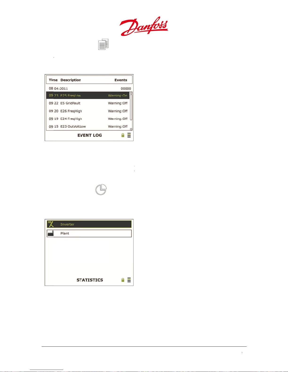
t
m
n
n
g
8
t
t
t
s
v
e
n
n
s
v
e
u
r
n
e
n
n
n
a
r
s
p
D
G
–
a
n
D
–
s
h
t
e
c
g
t
m
n
e
a
e
a
a
t
0
6.1.7
Even
the
Figur
War
War
Even
.
Log display
ost recent e
6.10: Events in
ing On mea
ing Off mea
Log
information
ent first.
the log
s that a war
s that an ev
about the i
ing event h
ent has clea
verter’s logg
Up or
Left –
Right
s occurred.
ed.
ed events. T
own – Read
o back to th
Go to next s
e events ar
he different v
previous scr
reen
listed with
lues
en
6.1.8
Statis
savin
Figur
6.1.
Inver
mon
Stati
.
tics displays
s and peak
6.11: Submen
.1. Inve
er displays a
h, this year a
tics
alues for th
power. The i
s to Statistics
ter
summary of
nd in total si
daily, mont
formation i
the most im
ce Start Up.
hly, yearly a
read-only.
Up or
Enter
ortant stati
d total ener
own – Read
Select a sub
tics of the i
y harvest, e
he different v
enu/confirm
verter from
rnings, CO
lues
oday, this
2
66
U
ser Guide DLX UL
series L00410625-
01
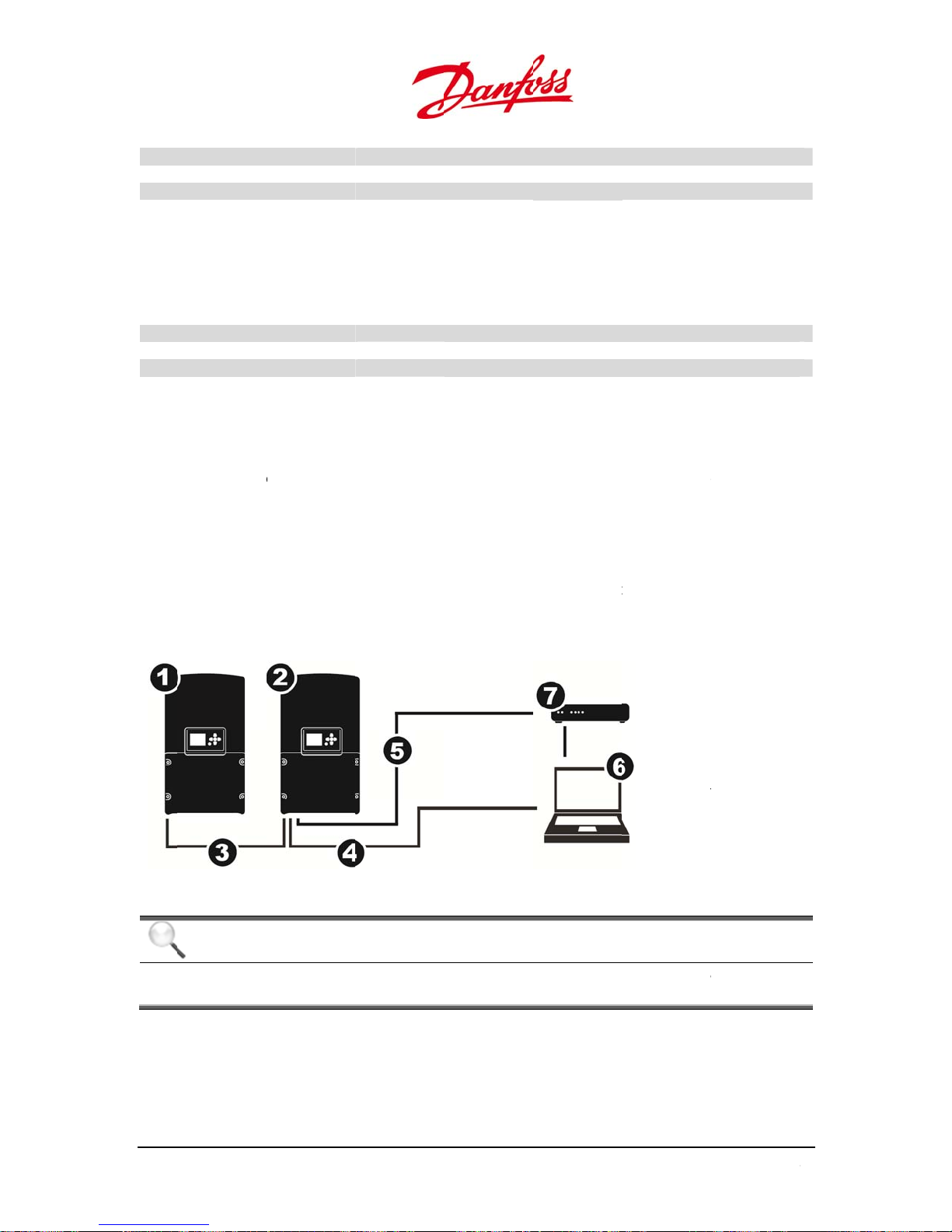
u
g
i
a
k
8
t
g
i
a
k
C
p
n
T
o
e
e
t
u
c
c
h
o
v
F
C
c
n
t
t
y
n
m
h
m
s
e
h
m
I
e
u
o
n
d
e
t
g
W
s
c
n
g
W
r
a
r
n
a
k
o
o
p
k
o
e
C
T
t
e
h
n
d
W
o
t
r
o
t
e
m
a
a
a
Ener
Earn
CO2
Pea
y
ngs
voided
Power
Inverter’s total
Cash value of t
Avoided CO2 e
Inverter’s large
energy produc
e feed-in ener
issions [kg/k
t instantaneou
ion [kWh]
y in currency/
h] compared t
s amount of p
Wh
fossil fuel
wer productio
[W]
6.2.
6.2.1
6.1.
Plant
mon
h, this year a
Ener
Earn
CO2
Pea
Power
Site
the i
.
o c
nnect the in
wher
need
.2. Plan
displays a s
y
ngs
voided
onne
erformance
verter and t
With
the networ
d.
mmary of th
nd in total si
tion be
an be moni
e computer
ut a Ne
erter directl
k card in the
e most impo
ce Start Up.
Plant’s total en
Cash value of t
Avoided CO2 e
Plant’s largest i
tween
ored remot
can be confi
work
to a comp
computer d
rtant statisti
rgy productio
e feed-in ener
issions [kg/k
nstantaneous a
nverte
ly by using
gured direct
ter a standa
es not supp
s of the PV
[kWh]
y in currency/
h] compared t
mount of pow
and P
computer.
ly or via a ne
d Ethernet c
ort Autosens
lant from to
Wh.
fossil fuel
r production [
he connecti
work.
able is requi
, a crossove
1. Foll
2. Mas
3. CAN
4. Eth
5. RS-4
6. Co
7. Dat
ay, this
]
on between
ed. In cases
r cable is
wer inverter
er inverter
bus cable
rnet cable
85 cable
puter
logger
igure 6.12: Con
NOTI
E
With se
be atta
veral inverte
hed to the
User G
ide DLX UL series
L00410625-01
ection without
rs connecte
aster invert
etwork
together vi
r only.
CAN bus, t
e Ethernet c
ble should
6
7

1
T
2
b
t
n
p
a
e
p
e
g
a
p
c
c
t
c
o
i
A
y
m
d
d
e
n
u
S
w
u
s
o
a
a
f
K
a
e
w
r
P
t
o
a
r
o
n
P
r
a
s
g
a
o
a
H
g
c
m
u
0
f
Star
r
e
I
a
c
t
e
8
g
s
b
a
v
1
C
e
u
u
e
8
e
d
d
7
p
m
h
o
i
t
t
v
t
o
5
w
0
s
e
6.2.
he c
is 19
num
Inver
The i
Setu
To st
addr
Com
The
chan
oper
1. O
2. Cli
3. Cli
4. Sel
5. Sel
En
Cli
*Wind
countr
.1. IP A
omputer an
.168.10.X, th
ers betwee
er
verter defa
>Network
rt the web c
ss into the
uter
xample belo
e the comp
ting system
en the netw
k Control P
k Local Are
ect Internet
ect Use the
er the defau
k OK and O
ws is either a re
es.
dress
the inverte
computer I
1 and 254.
lt IP address
etup and se
onnection t
eb browser
w shows the
ter’s IP add
(OS):
rk menu by
nel > Netw
Connectio
rotocol Ve
ollowing IP
lt parameter
istered tradem
IP address
address m
is 192.168.1
the inverter
the inverter
ddress line.
steps to be
ess. This pro
clicking
rk and Sha
> Properti
sion 4 (TCP/
ddress.
: IP address
rk or a tradem
ust be in th
st be 192.16
.20. To chan
IP address a
, open a we
ollowed on
cedure may
ing Center
s
Pv4) > Prop
192.168.10.
rk of Microsoft
same rang
.10.Y, wher
e the IP ad
required.
browser an
Windows®
ary on com
erties
10, subnet
orporation in t
. If the inver
X and Y are
ress, naviga
type the in
computer
uters with
ask 255.25
e United States
er IP addres
different
e to:
erter IP
o Guidely
ther
.255.0.
and other
6.2.2
If a L
to an
auto
68
With
.
N or WAN n
RJ45 port,
atically assi
Netw
twork is av
here the D
n a dynami
rk
ilable, the in
CP (Dynami
IP address
verter can b
Host Config
o the comp
hard wired
uration Prot
ter and the
by a CAT 5 n
col) server
nverter.
U
ser Guide DLX UL
etwork cabl
ill
series L00410625-
01
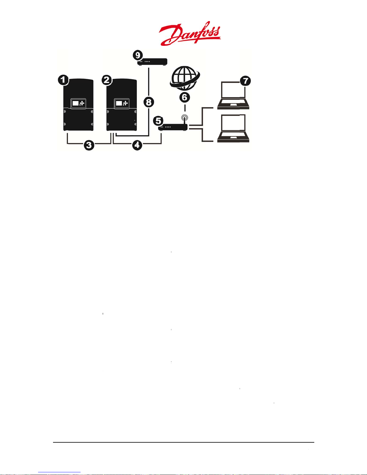
u
T
o
e
2
r
t(DH
e
2
r
t
dcom
e
d
n
The
c
r
u
1
v
o
e
e
e
G
o
e
e
e
G
s
r
u
g
w
A
o
D
p
0
c
P
p
e
e
T
d
e
P
W
n
e
d
e
n
f
t
e
a
s
e
s
e
k
e
h
o
e
A
e
g
a
g
o
o
e
o
s
N
e
r
m
4
a
y
g
e
s
g
m
1. Foll
2. Ma
3. CA
4. Eth
5. Rou
6. Wo
7. Co
8. RS-
9. Dat
wer inverter
ter inverter
bus cable
rnet cable
ter/Switch
ld Wide Web
puter
85 cable
logger
o c
of th
6.2.
Inve
1. Go
2. Se
3. Pr
6.2.
Inve
1. Go
2. Se
ad
3. Pr
Figure 6.
nnect the in
LAN RJ45 p
.1. With
ter
to Setup>N
the IP addr
CP) IP addr
ss OK. The
.2. With
ter
to Setup>N
the IP addr
ress must b
puter’s IP a
ss OK. The
3: Connection
erter to a L
rts on the r
DHCP –
twork Setu
ss to 000.0
ss automati
UI will restar
ut DHC
twork Setu
ss to a desir
an unused
ddress.
UI will restar
ith network an
N or WAN n
uter.
ynamic I
.
0.000.000.
ally to the i
t to configur
– Static I
.
d, unique a
IP address in
t to configur
World Wide W
twork, use
Addres
ith this setti
verter.
the new n
P Addres
dress for th
the networ
the new n
b
standard C
ng the rout
twork settin
inverter (St
and in the s
twork settin
T5 or better
r assigns a d
s.
tic). The inv
ame range a
s.
cable to any
namic
rter’s IP
the
6.2.3
In or
withi
1.
se
2. Po
ro
User G
Acce
.
er to make t
the netwo
inverter m
tion.
t Forwardin
ter is for We
ide DLX UL series
s from t
he inverter(s
k settings.
st be assign
must be set
b traffic (HT
L00410625-01
he Inter
) accessible
d a static IP
up within th
P), and mus
et
rom the inte
address in t
e local netw
be forward
rnet, further
e local netw
rk router. P
d to the inv
parameters
ork. Refer to
rt number 8
rter’s static I
ust be set
the previous
0 of the
P address.
6
9
Thewe
hextuse
I
T
n
a
The
m
Typ
f
This
r
C
x
s
r
s
m
d
r
e
T
o
w
y
t
m
r
m
a
e
t
n
a
h
h
o
o
e
r
y
e
r
c
r
h
c
b
e
n
d
s
n
u
n
e
u
a
r
n
t
p
s
s
o
e
d
0
e
p
d
o
c
o
h
.
e
o
d
o
h
d
x
a
b
o
g
w
o
e
h
c
o
p
d
d
y
i
n
e
o
s
n
v
n
e
k
S
f
s
a
o
o
0
c
external IP
b services, o
ddress of t
by asking t
e router can
e relevant I
be found at
ternet Servi
http://www.
e Provider (I
hatismyip.c
SP).
m or similar
6.3.
3. W
NOTI
If the e
addres
inverte
service
hostna
an IP a
In orde
must b
his wil
details
If the o
has a d
DNS se
en this is co
ernal IP add
d) in the co
nterna
E
ternal netw
is unlikely t
owner to s
for comme
e (such as:
dress that r
to have the
capable of
l most likely
f the user a
ner’s route
namic exter
tings will be
pleted it s
ess of the lo
puter’s we
l Webs
rk is assign
remain con
t up an acco
cial and priv
ourname.se
gularly chan
dynamic DN
eporting its
be present i
count with
does not re
nal IP addre
required.
ould be pos
al network
browser.
rver
d a dynamic
stant over a
nt with a c
te users, w
viceprovider
ges.
S service op
IP address t
the router s
he dynamic
ort its IP ad
s, then peri
ible to reac
r the web a
IP address fr
long time p
mpany that
ich allows t
org) that poi
rating corre
the dynami
ettings secti
DNS service
ress to the
dically a Gui
the DLX UL
dress (if a d
om the ISP, t
riod. It is po
provides dy
e user to ha
nts to a com
ctly, the ow
DNS servic
n which as
provider.
ynamic DN
e update o
webserver b
namic DNS
his IP
sible for the
amic DNS
e a
puter with
er’s router
provider.
s for the
service and
the dynami
y typing the
ervice is
he i
oper
•
•
Fro
pas
•
•
De
the
verter has a
tion, warnin
webpage is
the intern
sword.
e the invert
ault adminis
can be cha
internet.
n internal, o
g/alarms an
best viewed
l webserver
r’s IP addres
rator accou
ged by the
board webs
energy pro
in Firefox 6.
some invert
in the com
t is: User: a
ser, and sh
rver providi
uction of th
or Internet E
r settings c
uter’s web
min, Passw
uld be chan
ng detailed
e inverter/pl
plorer 8.0 a
n be chang
rowser.
rd: admin.
ed if the we
nformation
ant.
d later versi
d via userna
b server is c
bout the
ns.
me and
nnected to
70
U
ser Guide DLX UL
series L00410625-
01

u
H
spow
o
rove
e
i
s
o
n
t
a
.
a
o
n
h
t
r
C
s
t
n
y
e
t
r
e
e
o
n
h
h
p
n
r
o
6.3.1
The
serve
•
Sy
•
PV
dro
•
Pr
•
Mo
Hom
.
ome screen
r.
tem status
er producti
plant: More
p-down me
duction sta
e detailed v
r the graphs
s the standa
hows the st
n and input
detailed inf
u under Pla
us shows th
lues from t
rd display, w
Figure 6.14: S
tus and ope
values on D
rmation for
to the righ
e energy yiel
e productio
hich is alway
andard displa
ating mode
and AC sid
pecific inver
.
d for the cur
data can b
s shown wh
of the invert
are listed t
ters in a pla
rent day, mo
viewed by
n opening t
er or the PV
the right.
t can be fou
nth and yea
overing the
e web
lant. Curren
d in the
.
mouse curs
t
r
User G
ide DLX UL series
L00410625-01
7
1
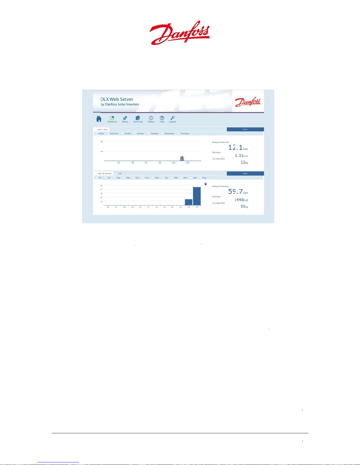
a
rove
e
The
T
d
t
>
€
>
n
P
a
s
s
n
a
.
.
m
a
c
a
M
n
w
h
o
s
s
r
o
n
h
v
n
d
o
o
M
i
W
a
t
h
s
t
n
l
n
o
e
f
r
w
o
t
e
e
n
.
o
m
n
p
o
n
t
o
c
t
n
m
s
f
0
8
8
6.3.2
Statis
the l
•
PV
dro
•
Mo
For G
•
Th
ava
•
fun
he
<dp
<en>
<pw
<va>
</dp
dp: D
en: E
pw:
va: E
Stati
.
tics gives a g
st 12 month
plant: More
p-down me
e detailed v
r the graphs
UI revision 1
energy log
ilable).
energy dat
tionality m
ata may be i
ime=”YYYYWWWW</e
wwww</p
€€€</va>
atapoint – t
ergy for the
eak power f
rnings/savin
i
77.78 Euro
tics
raphical ove
.
detailed inf
u under Pla
lues from t
32 and abo
ay be dow
downloade
y not work
ported int
M-DD HH:
>
>
e date and t
interval in
r the interv
gs for the in
view over t
Figure 6.1
rmation for
to the righ
e productio
e:
loaded by c
is determi
n certain m
a spreadsh
M:SS”>
me stamp o
h (watt-hou
l in watts
erval with t
e energy pr
5: Statistics
pecific inver
.
data can b
icking on th
ed by the u
bile devices
et program,
the entry
s)
o decimal p
duction fro
ters in a pla
viewed by
‘down’ arr
it selected i
with the da
ints, in the
the curren
t can be fou
lacing the
w (will be di
the dropdo
a format as
hosen curre
week and
d in the
ouse cursor
played if
wn box. This
ollows:
ncy, eg. ‘777
’
72
U
ser Guide DLX UL
series L00410625-
01

u
p
n
t
o
aPo
t
Typ
d
e
2
p
d
i
e
g
m
e
s
r
e
h
m
n
m
p
e
Typ
a
Typthe
The
r
d
oFor
t
r
r
s
r
.
r
m
e
C
t
t
e
1
a
(
a
v
n
F
o
m
c
d
w
v
f
n
e
e
d
a
g
g
2
r
w
t
c
m
m
0
a
d
a
)
a
p
h
n
T
e
a
e
T
m
,
A
.
o
e
a
6.3.3
Setu
•
Pla
seri
•
Ge
set
•
Ala
N
Al
•
Ne
an
•
Us
cha
Setu
.
shows the
t Informat
al number, r
eral Settin
ings can be
rm Setup sh
tification S
rm Setup:
rtal Setup:
work show
e the IP add
gateway. R
r Account s
nge user na
1
. Guest:
. Owner:
ifferent setti
on shows i
vision and
s shows dat
odified.
ows informa
tup:
IP
se
an
be
N
the parame
ess (configu
fer to 6.2.1.1
ows the cu
es and pas
Access level
Access level
gs and info
Figure 6
portant cha
art no. infor
and time,
ion related
e username
ddress of th
e time for s
messages (
inverter m
ver address
optionally
uploaded e
te: only an i
third-party
ers related t
ed with nu
. IP Address.
rent user ac
words. The
1: Read only
2: Read and
mation of e
16: Setup
acteristics o
ation are al
O2 - rating a
o notificatio
and IP addr
e inverter an
nding email
440 min = 1
y upload en
either IP ad
username
ery hour.
verter confi
TP services,
the sendin
bers like 19
ounts and p
ifferent leve
access to all
rite access
ery inverter
every inver
l read-only.
d rate and
ns and alar
ss/host na
d mail addre
messages (
day).
rgy data to
ress or DNS)
nd passwor
ured as a m
an addition
and receivi
.168.10.20
ovides the a
ls are:
values.
to all values
in the PV pla
er in the PV
urrency of t
s from the i
e of the SM
ss of the rec
– 23 h) and
n FTP-serve
in the FTP S
if needed.
aster will upl
l cost may b
ng of email
, network su
bility to setu
and set level
nt.
lant. Model
e earning.
verter/plant
P server, the
iver(s).
the interval
r. Specify th
rver IP field,
he data will
oad FTP dat
e applied.
essages.
bnet mask
p and/or
s except the
ll
f
.
User G
ide DLX UL series
L00410625-01
7
3
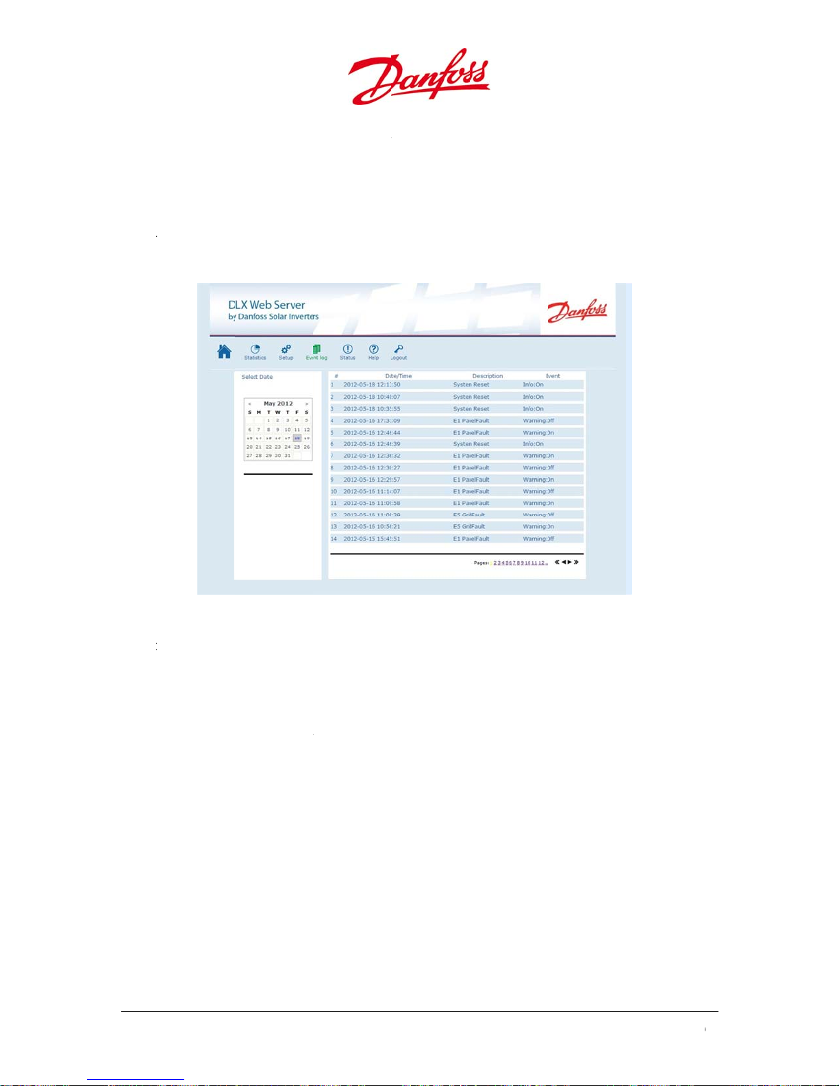
3
t
t
c
e
The
The
h
t
n
e
a
c
v
.
t
w
s
d
v
y
u
w
t
7
n
c
m
b
b
w
w
o
d
n
o
n
a
g
t
a
u
n
t
i
0
l
. Admin:
installer rela
Access level
ted values s
3: Read and
ch as netwo
rite access
rk settings a
to all levels
d user acco
nd set value
nts.
s.
6.3.4
Even
with
•
Re
bot
•
Ev
to t
For G
•
“do
•
if t
Even
.
Log shows i
he most rec
ent events c
tom of the s
nts from pre
he left.
UI revision 1
most recen
wn”-arrow (
latest event
e followers a
Log
formation a
nt event fir
n be viewe
reen.
ious month
32 and abo
events in th
ill be displa
s from the fo
lso have the
bout events
t.
Figure 6.1
by navigati
s and years
e:
e event log
ed if availa
llowers may
same or ne
hat the inve
: Event Log
g directly t
an be viewe
ay be dow
le).
e displayed
er GUI revisi
rter has log
the differen
by specific
loaded as a
and downlo
n as the m
ed. The eve
t pages in th
dates using
ext file by cl
aded. This is
ster unit.
ts are listed
e list on the
he calendar
cking the
only availab
e
74
U
ser Guide DLX UL
series L00410625-
01
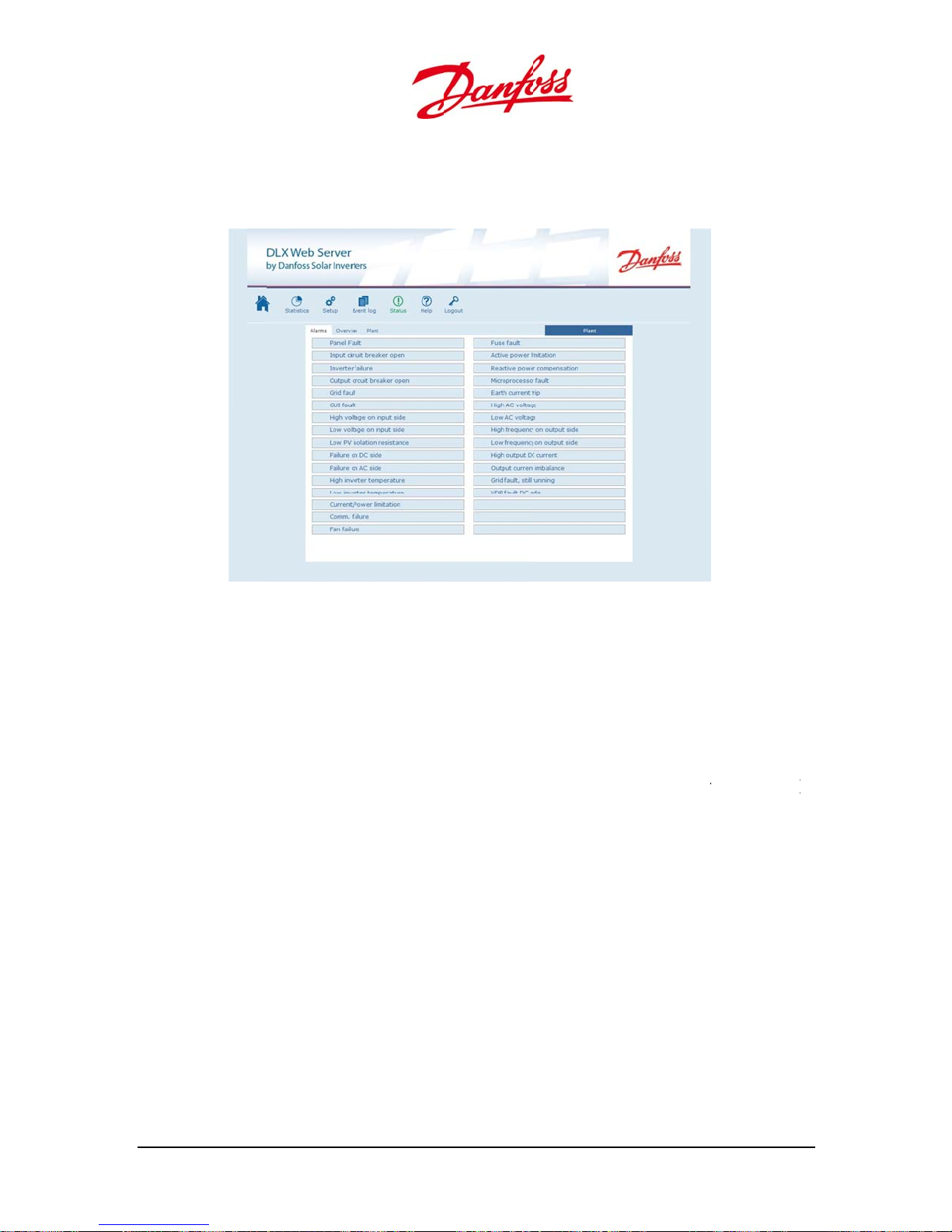
u
s
n
h
The
l
e
a
d
To r
y
e
n
a
m
y
s
n
n
n
e
r
o
g
n
m
e
a
m
v
t
p
n
l
s
v
i
v
,
a
a
a
s
2
r
i
s
)
)
6.3.5
Statu
tech
•
Ala
hig
fau
•
Ov
par
an
•
Pla
pro
Statu
.
displays an
ical charact
rms tab ide
lighted.
Extended St
ts.
rview provi
meters fro
total energ
t (available
vides a snap
efresh the i
s
warnings a
ristics and e
tifies any sp
tus lines are
des input pa
the inverte
production
in a unit con
hot of the c
formation, c
d alarms in
ergy yield.
Figure 6.
cific warnin
used by Da
rameters fro
/plant to th
with peak v
figured as a
nnected in
ick the ‘Plan
the plant, an
18: Status
or alarm in
foss service
the PV pa
grid, as wel
lues from th
aster when
erters, statu
’ tab.
d gives an o
the plant, w
ersonnel to
els to the in
as earnings
e inverter/pl
selecting ‘Pl
and energy
erview of th
th any activ
help diagno
erter/plant,
avoided CO
nt.
nt’ in the d
production
e plant’s
ted items
e possible
the output
emission
op down list
nformation.
User G
ide DLX UL series
L00410625-01
7
5

T
T
c
k
n
C
Th Th Th Th Th Th
t
T
T
n
s
W
A
D
r
B
a
a
n
o
L
a
e
m
n
n
a
e
s
s
H
r
y
F
o
a
c
o
s
o
h
f
s
n
b
e
u
h
I
f
t
e
o
e
r
m
n
o
t
g
:
e
e
g
m
e
o
(
>
e
y
o
a
s
p
s
s
o
o
e
c
L
T
s
o
s
n
h
:
r
d
s
i
e
n
L
e
0
b
.
7.
7.1.
his
chec
the i
probl
em, please c
If the
If all
hese items a
ROU
hapter cont
ing the inst
formation i
heck
inverter doe
at both the
at the irradi
at the oper
at there are
at all conne
at the valu
LES
ins useful in
llation is car
7.2. Table of
ntact the s
ist by
s not feed p
AC and DC d
tion is suffi
tion mode
no warning
ction points
s of the PV v
re OK, and t
OOT
ormation if
ied out corr
Events for p
stem install
ailure
wer to the g
isconnect ci
ient to gene
f the LEDs is
or alarms in
in the syste
ltage, curre
ere is still n
NG
he inverter
ctly, and th
ssible soluti
r.
rid, try to sol
cuit breaker
rate power (
normal (Ref
the display (
are properl
t and powe
power fed t
alfunction
display inf
ns. If this d
ve the probl
s)/disconne
7 W).
r to 5.1.2.2.
Refer to 7.2.
tightened.
r match tho
the grid, c
during ope
rmation, an
es not help
m by check
t(s) are ON.
EDs).
able of Even
e in the disp
ntact your d
ation. Start
then check
olve the
ing:
ts).
lay.
istributor.
y
7.2.
he i
scree
n. Detailed i
Refer
Mes
ages that c
W =
A =
larm (Red LE
The
desc
able o
verter auto
to 6.3.4. Eve
arning: inv
isplay Mes
iption as di
Event
atically ide
formation a
t Log.
n appear in
rter continu
D)
age code n
played in t
tifies opera
out warnin
the display
s to operat
mber (E01,
e Event Lo
ional issues
s and alarm
at highest
E02, etc..) i
of the web
nd displays
can be fou
ossible capa
the code s
server view
the messag
d in the Eve
city (Yellow
own in the
s on the
t Log menu
ED)
vent
76
U
ser Guide DLX UL
series L00410625-
01
u
7
p
e
2
r
p
f
h
7
8
u
o
e
/
a
E
0
p
e
e
e
p
n
i
o
y
h
e
n
e
r
r
n
0
r
T
y
T
y
t
e
e
h
h
e
G
T
s
n
p
c
v
d
r
T
u
c
h
.
G
m
o
v
A
a
A
u
r
h
t
t
m
>
y
y
W
n
h
h
m
3
s
a
i
t
P
u
t
e
u
e
n
e
y
y
g
t
,
e
Table
Dis
Pan
.1: Description
lay Messag
l fault (W/A –
f messages app
E01)
aring in the dis
Descriptio
PV module fa
lay during inve
lure
ter failure
Action
- Contact
the supplier*
Inpu
t circuit break
– E0
)
Inve
ter failure (W
Out
ut circuit bre
(A –
E04)
Grid
fault (W/A –
ault (W/A – E
GUI
Hig
voltage on in
– E0
)
er open (A
A – E03)
ker open
05)
6)
put side (A
DC switch is
Inverter failur
AC circuit bre
No detection
not able to s
with the grid
setting the gr
Display is not
DC voltage t
V
is exceed
DC
pen
e
aker(s) is ope
of the grid,
nchronize
or fault when
id-settings
responding
reshold of 60
d
-
-
If alread
- Contact
-
-
If alread
- Verify if
and op
- Measur
present
-
Check t
that the
-
Check t
have be
Setup>
-
second
Wait 30
on
If still u
-
the sup
-
Contact
urn on
urn on
urn off
the DC switc
y on, contact
the supplier
the AC circuit
y on, contact
the AC circuit
rational
that the grid
at the AC ter
at the DC swi
DC power is
at the countr
en successfull
rid Setup
the AC side.
and then tur
seconds for t
responsive, t
lier
the supplier
*
he supplier
breaker(s)*
he supplier
breaker is on
voltage is
inals
tch is on and
7W
settings
set in
ait for 3
on again.
e GUI to turn
en contact
Low
voltage on in
)
– E0
Low
PV isolation r
E09)
(W –
re on DC side
Fail
E10)
ut side (A
sistance
(W/A –
DC voltage is
operate the i
PV isolation r
below the pe
Inverter failur
side
too low to
verter
sistance is
mitted level
e on the DC
- Fault is
PV volta
-
If the in
during
supplie
-
he gro
incorre
- Check t
setup (4
System
- If the ju
contact
- Failure
are also
-
If the in
off the
side. W
on the
- If the fa
supplie
-
leared auto
ge exceeds 2
erter remain
aylight, cont
nding setup
tly
e jumper for
.3.4.7 Jumper
rounding Set
per is correc
the supplier
n the DC sid
shown
erter is in Sh
C side and th
it for 30 seco
C side and th
lt persists, co
atically when
0V
in this fault
ct the
s configured
he groundin
osition for
p)
ly positioned
. Other W/A
tdown, turn
n the DC
ds, then turn
n the DC sid
ntact the
,
User G
ide DLX UL series
L00410625-01
7
7
Dis
p
u
h
A
p
e
A
m
f
e
v
8
c
e
p
m
a
7
a
/
e
a
n
r
t
i
m
s
D
o
v
A
a
A
u
r
h
a
a
i
n
e
i
T
e
h
i
i
n
e
i
v
A
a
A
u
r
m
m
u
e
n
e
n
e
r
e
o
e
a
e
r
e
u
e
n
e
o
o
0
e
n
e
lay Messag
Fail
re on AC side
E11)
Hig
inverter tem
(W/
– E12)
(W/A –
erature
Descriptio
Inverter failur
side
Maximum pe
internal inver
temperature
e on the AC
missible
er
s exceeded
Action
- Failure
are also
If the in
-
off the
side. W
on the
- If the fa
supplie
- Check t
temper
specific
Data)
- Check if
the min
complia
Guide a
from dir
-
Clean v
Ventilat
n the AC side
shown
erter is in Sh
C side and th
it for 30 seco
C side and th
lt persists, co
at the ambie
ture is within
tion (Refer to
the ventilatio
mum distanc
nt with those
d the inverte
ect sunlight
ntilation (Ref
on)
. Other W/A
tdown, turn
n the DC
ds, then turn
n the DC sid
ntact the
t
the
10 Technical
n is sufficient,
s are
in this User
is shielded
r to 8.2.8
Low
inverter
erature(W/A
tem
Curr
nt / power li
(W/
– E14)
Co
munication f
E15)
ailure (W/A –
Fan
Fus
fault (A – E1
– E13)
itation
ilure (A –
E16)
)
Low internal i
temperature
PV power exc
rating
Internal com
failure
Internal air di
missing
One or more
blown
nverter
eeds inverter
unication
tribution is
C fuses are
- Contact
-
he inv
when t
permiss
- Check if
the min
complia
Guide a
from dir
-
Clean v
Ventilat
- If the in
off the
side. W
on the
- If the fa
supplie
- Contact
replace
- Contact
replace
the supplier
rter will try t
e temperatur
ble range ag
the ventilatio
mum distanc
nt with those
d the inverte
ect sunlight
ntilation (Ref
on)
erter is in Sh
C side and th
it for 30 seco
C side and th
lt persists, co
the supplier f
ent fan
the distribut
ent fuses
start up agai
is within the
in
n is sufficient,
s are
in this User
is shielded
r to 8.2.8
tdown, turn
n the DC
ds, then turn
n the DC sid
ntact the
r a
r for
Acti
e power limit
– E1
)
Rea
tive power
com
pensation (W
78
tion (W/A
A – E19)
- Contact
- Contact
-
the supplier*
the supplier*
U
ser Guide DLX UL
series L00410625-
01
u
p
o
u
h
h
h
6
p
7
e
u
A
A
n
u
e
n
T
v
s
T
o
s
T
y
o
T
y
o
T
p
e
t
e
)
t
s
v
A
a
A
u
r
T
e
h
c
r
T
e
h
c
r
T
e
u
i
h
c
T
e
u
i
h
c
r
T
e
t
u
r
u
e
n
e
r
p
c
i
c
r
p
c
i
c
e
n
c
i
c
e
n
c
i
c
e
e
d
d
d
m
d
Dis
Micr
E20)
lay Messag
processor fa
lt (W/A –
Descriptio
Action
- If the in
off the
side. W
on the
- If the fa
supplie
erter is in Sh
C side and th
it for 30 seco
C side and th
lt persists, co
tdown, turn
n the DC
ds, then turn
n the DC sid
ntact the
Gro
nd current tri
Hig
AC voltage (
Low
AC voltage (
frequency o
Hig
side
(W/A – E24)
(A – E21)
– E22)
– E23)
output
oo high AC
inverter stop
power
oo low AC v
inverter stop
power
he frequenc
voltage is ab
limit
oltage, the
feeding
ltage, the
feeding
of the grid
ve the upper
- Contact
-
he inv
voltage
range
-
Check t
been su
Setup
-
If the fai
supplie
-
he inv
voltage
range
-
Check t
been su
Setup
If the fai
-
supplie
-
he inv
the freq
permiss
- Check t
been su
Setup
-
If the fai
installer
the supplier*
rter will resta
is within the
at the grid se
cessfully set
lure persists,
rter will resta
is within the
at the grid se
cessfully set
lure persists,
rter tries to r
uency is withi
ble range
at the grid se
cessfully set
lure persists,
t when the
ermissible
ttings have
n Setup > Gri
ontact the
t when the
ermissible
ttings have
n Setup > Gri
ontact the
start when
the
ttings have
n Setup > Gri
ontact syste
Low
frequency on
side
(W/A – E25)
output DC c
Hig
– E2
)
Out
ut current im
– E2
)
User G
ide DLX UL series
output
rrent (W/A
alance (W
L00410625-01
he frequenc
voltage is bel
limit
oo high pro
current in th
Imbalance in
current betw
(3 phase only
of the grid
w the lower
ortion of DC
grid feeding
he output
en the phase
-
- Check t
-
-
- If the fa
-
s
he inv
the freq
permiss
been su
Setup
If the fai
supplie
he inv
the faul
supplie
Contact
rter tries to r
uency is withi
ble range
at the grid se
cessfully set
lure persists,
rter tries to r
is cleared
lt still occurs,
the supplier*
start when
the
ttings have
n Setup > Gri
ontact the
start when
contact the
7
9

Dis
p
e
e
n
(
u
e
n
o
T
o
.
e
o
0
lay Messag
Grid
fault, still run
E28)
ing (W –
Descriptio
Fault ride-thr
ugh
Action
- Contact
the supplier*
VDR
* Res
fault DC side
rved for fut
W – E29)
re use
he varistors
are damaged
n the DC sid
-
Contact
the supplier f
r new parts
80
U
ser Guide DLX UL
series L00410625-
01
u
M
T
c
v
D
S
y
p
i
i
R
D
t
T
a
r
e
G
p
c
T
e
T
e
t
N
v
d
r
t
a
C
e
n
m
t
N
w
k
d
b
o
y
n
m
n
f
n
e
e
r
p
b
c
n
e
m
o
t
s
o
o
d
v
o
e
e
n
t
s
o
r
p
w
n
w
o
p
e
t
D
e
o
s
p
t
s
8.
8.1.
his
over
the
AIN
hapter expl
iew of impo
LX UL invert
witch-
ENA
ins how to s
tant regular
rs. Finally, it
OFF
CE
itch OFF a
maintenanc
is explained
d discharge
procedure
how to rem
the inverter
to ensure tr
ve and retu
afely. It also
uble-free o
n the invert
provides an
eration of
rs.
Alwa
or re
AC-s
•
DC-s
•
•
•
s turn OFF a
airs:
DAN
Never
side be
de
urn OFF th
de
urn OFF th
Disconnect
Let the DC c
WAR
Lethal
charge
service
nd disconne
ER
erform wor
ause of dea
AC circuit
DC switch.
he connect
apacitor ban
ING
oltages ma
capacitor b
or maintena
ct the invert
on the inve
ly voltages
reaker(s).
rs.
k discharge.
be present i
ank. It must
ce work on
r in the foll
ter without
resent at th
nside the in
e discharge
the inverter.
wing order
isconnectin
e terminals.
erter after s
d for 1 hour
rior to main
g both the
itch OFF, b
before perf
enance wor
C and AC
cause of a
rming
k
8.2.
The
Perfo
inver
User G
egula
LX UL inver
rming regul
er.
ide DLX UL series
NOTI
Only p
Mainte
perfor
warran
Syste
ers are desig
r maintenan
E
rmit qualifie
ance work i
ed by quali
y.
L00410625-01
Inspe
ned and ma
ce will ensur
d persons to
volving re
ied persons
tions
ufactured t
high effici
perform the
oval of the i
nly, due to
operate tro
ncy and a lo
work inside
verter’s lo
he requirem
uble-free for
ger service
the inverter!
er cover mu
ents of the
several year
life for the
t be
roduct
.
8
1

t
a
u
w
The
C
a
T
u
m
e
n
r
h
o
s
f
n
s
u
,
G
o
e
s
d
o
G
c
d
m
n
n
D
p
n
/
m
o
n
o
b
k
d
g
t
s
r
u
o
s
w
e
n
a
z
a
f
t
a
o
e
D
h
d
n
k
n
“
x
e
e
l
n
e
R
o
r
0
8.2.1
Main
8.2.2
Regu
Repl
8.2.3
Regu
not d
8.2.4
Freq
circui
•
Al
rep
•
Mod
.
ain the PV
Cabl
.
larly check al
ce frayed co
Elect
.
larly check t
eteriorated
Fuse
.
ently blown
t or ground
ays determi
lacement/re
replacemen
les
odules as re
s
l cables insi
ductors im
ical Co
at the termi
r corroded.
/Circuit
fuses or trip
ault.
e the reaso
etting.
resetting
t
ommende
e and outsid
ediately!
nection
als and plu
o not forge
Breaker
ed circuit b
for blown f
ust be perf
from the m
e for signs o
s are firmly
the combin
eakers are a
ses/tripped
rmed by qu
nufacturer.
thermal an
ightened, a
er box!
clear warnin
circuit brea
lified perso
mechanica
d that the i
g sign of ov
ers prior to
s only!
damage.
sulation is
rload, short
8.2.5
If a D
Table
Repl
•
ur
DC F
.
fuse blows
of Events).
DAN
The ph
produc
holder
expose
cement Pr
n OFF both t
DAN
Always
cover d
ses / Gr
the followi
ER
tovoltaic m
hazardous
after switch
to light!
cedure
e AC circuit
ER
disconnect
ue to the ris
und Fu
g message
dules (pan
voltages, wh
OFF. Do not
breaker(s) a
oth the DC
of shock ha
e
ill appear in
ls) deliver p
ich is still pr
replace the
d DC switc
nd AC sides
ards.
the display:
wer when e
sent at the t
C fuses wh
.
before open
“Fuse fault” (
posed to lig
erminal bloc
n the PV m
ing the inve
efer to 7.2.
ht and
ks and fuse
dules are
ter’s lower
82
U
ser Guide DLX UL
series L00410625-
01
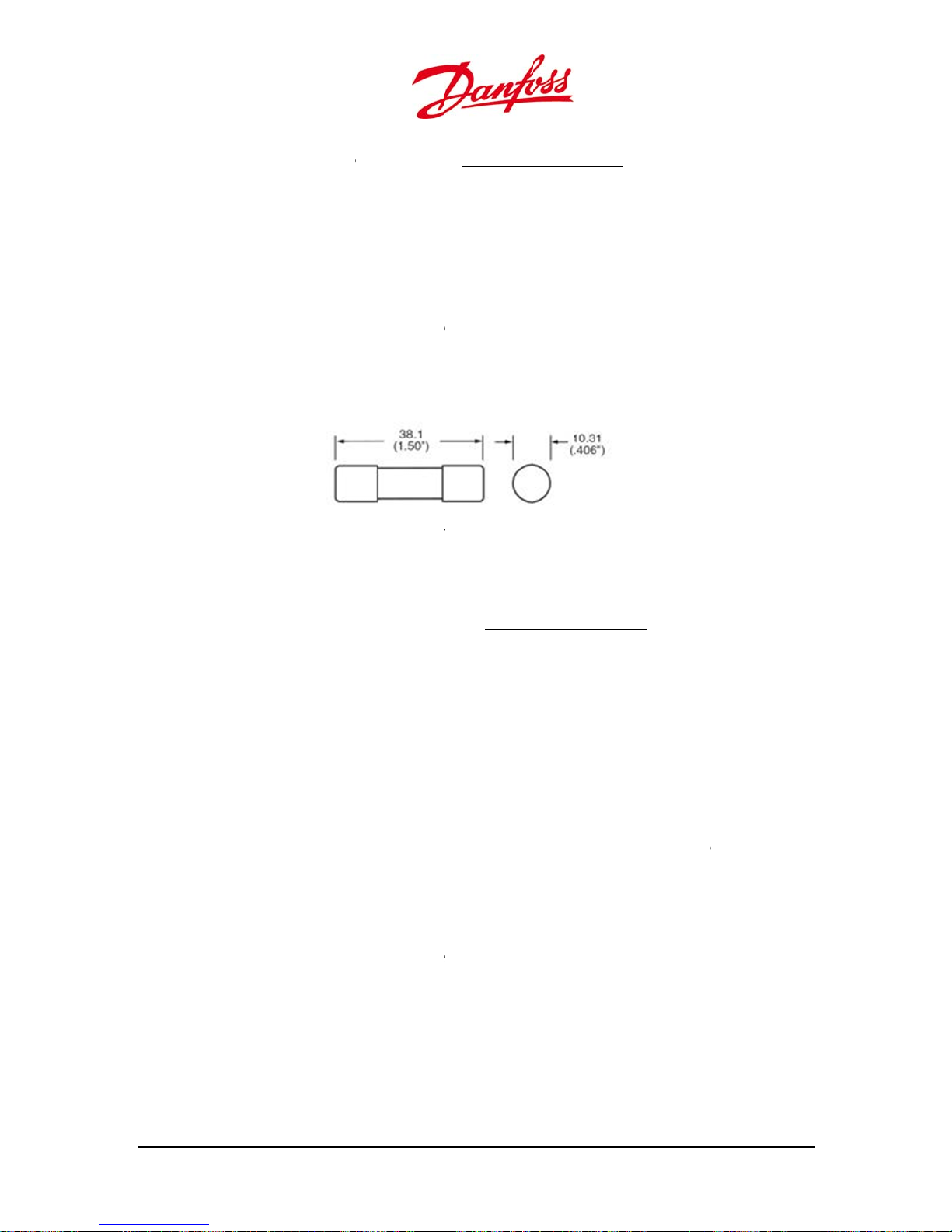
u
m
e
w
a
e
o
tmea
h
w
k
e
t• Turn
T
e
a
n
y
T
h
p
T
s
e
e
r
y
M
e
a
c
i
n
o
t
e
h
m
c
a
e
s
e
w
1
f
t
v
e
c
t
2
s
o
o
c
t
u
e
u
m
a
o
o
e
m
f
D
h
y
e
d
e
s
r
t
e
a
i
e
r
t
o
r
n
s
i
e
o
e
t
g
o
e
c
r
s
h
f
m
y
r
a
a
e
d
n
F
a
o
h
.
a
•
Re
•
Ch
•
Al
•
DC
Fuses: Meas
me
rev
•
Gr
gro
und termina
vol
•
If t
•
Al
ove the inv
ck that the t
ays check th
surable cur
rsed polarit
und Fuse:
age measur
surements
e voltage an
ays exchang
rter’s lower
rminals are
e cause of th
ure the volt
ent do not r
.
easure one
l block, and t
ments shou
re different,
d current m
e the fuses
over (Refer
voltage free.
e defective f
ge and curr
move the f
tring at a ti
hen the neg
ld be equal t
there is a gr
asurements
ith the sam
o 2.4.5. Inve
se prior to r
nt: If the vol
se holder. R
e: The volta
tive termin
the open c
und fault. R
are correct,
type and ra
ter Enclosur
eplacement.
age is close
check wirin
ge between
l and the gr
ircuit voltag
peat for ea
emove and
ing.
).
o or 0 VDC o
for dead sh
the positive
und termin
(V
) divid
OC
h string.
eplace the
there is a
orts or
nd the
l block. Bot
d by 2. If the
efect fuse(s)
•
Ma
fus
•
Fas
8.2.6
o pr
oper
8.2.7
The i
ever
8.2.8
he
com
his i
e sure that t
holder.
en the inver
on the AC
DC D
.
vent weldi
ted at least
Inver
.
terior of th
3 – 4 years.
Venti
.
eatsink on t
onents and
accomplish
Figure 8.
he replaced
er lower co
ircuit break
sconne
g of the con
nce every 1
er
inverter mu
lation
e backside
ust be clea
ed by using
: Dimensions of
use(s) is co
er firmly (Re
r(s) and the
t Switc
acts, thereb
months, pr
t be checke
f the invert
n to ensure
ne of the fo
the DC fuses/gr
pletely inse
er to 2.4.5. I
C switch.
extending
ferably at n
by the syst
r conducts h
ufficient co
llowing:
und fuse
ted in the fu
verter Enclo
ervice life, t
ght or when
m installer
eat away fro
ling, thereb
se holder, a
ure).
e DC switch
the AC is O
or humidity
the electr
preventing
d insert the
(es) must be
F.
nd dust
nic
yield losses.
User G
ide DLX UL series
L00410625-01
8
3

T
a
e
m
m
n
h
t
a
t
s
e
o
o
h
t
n
e
l
e
c
n
o
l
R
e
r
r
o
t
e
p
d
c
ft
m
i
e
e
s
m
e
f
n
n
o
o
r
m
2
v
e
c
s
0
e
2
•
Va
uum cleaner
•
So
t brush
•
Co
pressed air
Figur
8.2: Heatsink c
eaning
8.2.9
he f
conv
and
•
A
Eve
•
If t
cer
ag
Fan
.
n circulates
rsion capaci
ust be perf
essage is sh
ts.
e fan fails, t
ain tempera
inst overhea
the air insid
ty. The repla
rmed by Da
wn in the di
e inverter c
ture thresho
ting.
the inverte
ement of th
foss autho
Figure 8.3: P
splay when
ntinues to f
d, at which
, which distr
e fan requir
ized servic
sition of the fan
he fan need
ed the maxi
oint it starts
butes heat a
s removal o
persons o
replaceme
um amoun
to reduce p
nd thereby
the inverter
ly!
t. Refer to 7.
t of power a
wer to prot
aintains th
upper cover
. Table of
ailable until
ct itself
a
8.2.1
Varis
expo
84
Varis
0.
ors have a fi
ed to transi
ors (VD
ite life expe
nts. They th
)
ctancy, and
refore need
egrade and
regular insp
lose their pr
ections (eve
tective fun
y six month
U
ser Guide DLX UL
tion when
).
series L00410625-
01

u
a
m
1
m
E
p139• Thecom
t
1
y
p139• Thecom
t
u
f
S
o
m
r
b
o
S
w
e
y
m
o
b
o
l
u
i
o
s
w
d
o
C
t
t
s
a
a
t
c
s
d
s
a
a
v
e
f
o
i
d
t
e
g
o
s
c
a
i
t
h
a
h
R
e
T
u
e
Repl
and
cement req
ust be per
ires remova
ormed by q
of the inver
alified per
er lower co
ons only!
er and the u
e of the VD
service tool
,
8.2.
•
A
of
•
Re
•
No
0.1. DC
essage is sh
vents.
lace the da
B0570
two varisto
partment a
e the positi
ide
wn in the d
aged varist
s on the DC
ove the net
ns of the var
splay when
r with DC V
ide are loca
ork conne
istors if they
DC varistor
ristor Kit ord
ed on the le
tions.
are in need
needs repla
red from D
t side of the
f replaceme
ement. Refe
nfoss, part n
inverter low
nt.
r to 7.2. Tabl
umber
r
8.2.
•
No
the
•
Re
•
No
User G
0.2. AC
arnings ar
need to be
lace the da
B0570.
three varist
partment a
e the positi
ide DLX UL series
ide
given regar
checked reg
aged varist
rs on the A
ove the AC
ns of the var
L00410625-01
Figure 8.4: Vari
ing the con
ularly (at lea
r with AC Va
side are loc
erminal are
istors if they
tors on the DC s
ition of the
t once a yea
ristor Ki
ted in the ri
.
are in need
ord
de
varistors on
r) or after lig
red from D
ht side of t
f replaceme
the AC side.
htning strike
nfoss, part n
e inverter lo
nt.
herefore,
s.
mber
wer
8
5
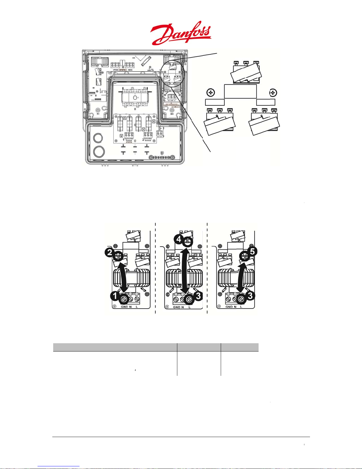
8
a
w
w
w
a
e
The
V
s
e
m
v
o
t
F
m
)
t
e
V
d
a
s
e
k
i
n
a
Ω
Ω0 Ω
a
h
p
p
m
∞
∞ ∞
t
a
f
u
0
f
s
Figure 8.5: Vari
tors on the AC s
de
k of the AC
Chec
ure the ohm
Meas
the b
Table
Me
Bet
Bet
Bet
low diagra
.1: Check if the
surements
een GND (1
een L (3) an
een L (3) an
aristors
(resistance)
s:
aristors are da
and the lef
d the middl
d the right
between th
igure 8.6: Chec
aged
VDR (2)
VDR (4)
DR(5)
terminal a
ing the AC varis
Undam
0
0
d the bent
tors
ged Da
in on each v
aged
Ω
Ω
Ω
ristor as per
Repl
•
Us
cement Pr
the service
service tool
cedure
ool delivere
is designed
86
in the pack
s a fork, and
ging with t
can open u
e new varis
all terminal
ors ordered
clamps sim
U
ser Guide DLX UL
rom Danfos
ltaneously.
series L00410625-
.
01

u
e
m
e
R
T
n
m
c
m
l
l
n
g
t
e
b
C
a
N
r
h
o
e
h
e
g
r
n
F
t
e
w
w
o
n
e
e
n
g
t
w
s
c
u
o
t
o
s
r
v
o
e
e
o
t
e
t
e
r
i
a
t
d
t
v
e
•
•
•
Op
Co
Us
n the termi
ply with Fi
the service
Figure 8.7: Se
al clamps a
ure 8.4 and
ool to open
vice tool to ope
d remove th
igure 8.5 to
he clamps
the varistor te
e damaged
et the positi
hen insertin
minal clamps
aristor(s).
n of the var
g the new v
istors right.
ristor(s).
8.3.
8.3.1
•
•
•
•
•
he i
.
Re
Dis
Re
Pul
Pul
eplac
verter can
NOTI
Remov
only!
WAR
Always
inverte
shock
Dism
ove the inv
onnect bot
ove the scr
up the fixin
the inverter
Devic
e replaced
E
l of the inve
ING
disconnect t
is charged
azard if the i
unting
rter lower c
the DC and
ws J and K i
plate betw
up and slid
s
ithout disas
rter’s lower
he power so
ith lethal v
nverter is no
ver (Refer t
AC terminal
side the Stri
en the Strin
it out of the
embling th
over must b
rces prior t
ltages, and r
disconnect
2.4.5.2 Fron
.
ngbox.
gbox and th
mounting b
Stringbox.
performed
removal of
emoval of th
d.
Covers).
inverter.
acket.
by qualifie
he lower co
e lower cov
persons
er! The
r poses a
User G
ide DLX UL series
L00410625-01
8
7

Figur
d
e
e
t
e
i
a
c
w
e
e
v
o
t
e
m
n
e
o
a
a
e
r
b
S
S
0
)
8.8: Dismount
ng of the invert
r
8.3.2
•
Sli
Inv
•
Ch
are
•
Gui
•
Fas
Repl
.
e the new in
rter.
ck that the
aligned (3).
de the fixing
en the scre
cement
erter carefu
onnection h
plate I into t
s J and K wi
lly onto the
les on the i
he slot betw
h a torque
ounting br
verter (E, F
en the inve
f 1.48 ft-lbf /
cket (1 – 2
nd G below)
ter and the
2.0 Nm.
elow). Refer
and on the
tringbox (4)
to 4.1.2
tringbox (H
.
Figur
8.9: Procedure
for replacing th
88
inverter
U
ser Guide DLX UL
series L00410625-
01

u
l
h
The
hnee
This
o
R
8.4.
n
a
o
o
e
s
t
o
l
d
s
s
c
t
n
n
u
e
a
n
a
g
r
f
o
i
o
v
o
e
p
a
c
n
o
t
a
e
o
d
s
c
p
t
t
o
.
i
e
D
t
m
t
m
Se
e
c
a
t
w
o
e
n
t
e
p
t
s
e
u
o
s
o
t
e
d
a
a
Y
e
t
f
f
e
c
t
r
p
n
h
e
s
e
u
e
n
f
f
a
t
h
e
e
r
o
It is a
so possible
•
If t
e replaced i
rep
laced device
•
device num
•
If t
e replaced i
ds to be set
is done in S
log
Whe
replacing a
to st
te and feder
resp
nsibility and
envir
n-sequenc
eturn
nmental le
o add new i
verter is a f
and put it in
ber is autom
verter is th
p as master
etup>Netw
is performe
nd Di
inverter, it
l regulation
therefore a
islation and
verters or re
llower, the
o operation
tically main
master and
.
rk Setup>
.
posal
an either b
s. Danfoss is
peals to end
to seek safe
place existin
aster invert
.
tained.
aster funct
t as Master
returned to
ommitted t
users who a
nd responsi
g ones in a l
r will autom
ionality is de
nit. Select
the distribu
its policy o
re disposing
ble means o
rger PV syst
tically ident
sired, an exi
s, and an a
or or dispos
environme
inverters to
disposal.
m:
ify the
ting inverte
tomatic
d according
tal
ollow local
8.4.1
For r
In ca
inver
Prior
•
Lo
•
Pul
•
Pac
•
Ad
•
Ret
8.4.2
In ca
or di
Recy
regul
recyc
Retu
.
turn to Dan
e of return
er supplier.
to Return
sen the lock
the inverter
k the inverte
a fault rep
rn to the gi
Disp
.
e of return a
posed in th
ling and dis
tions appli
lable.
n
oss the inver
f the produc
ng screws a
up and out
r securely in
rt if relevant
en address
sal
s a result of
respective c
osal of the
able in the s
er should al
as a result
tached to th
f the bracke
the packagi
n the respec
nd of servic
ountry. Ship
LX UL inver
ate of dispo
ays be in it
f inverter fai
fixing clip
t.
g.
ive state.
life, the inv
ing to the d
er must be
al. All mater
original or
lure, please
n the moun
rter can be
istributor is
one accordi
ial used for t
quivalent p
ontact your
ing bracket.
eturned to t
aid by send
g to the rul
e inverter p
ckaging.
Danfoss
he distribut
r.
s and
ackaging is
r
User G
ide DLX UL series
L00410625-01
8
9
W
T
n
u
o
n
o
W
t
W
w
T
w
a
o
a
a
e
e
e
e
.
c
e
e
y
r
w
C
T
n
i
o
s
l
a
r
e
m
d
r
n
d
a
Y
w
h
o
p
i
n
r
n
u
e
t
y
v
h
e
r
m
c
e
n
t
a
a
m
s
e
o
e
o
l
s
d
T
c
a
e
h
r
o
n
e
h
e
n
G
r
h
t
a
g
o
d
w
s
i
e
0
o
u
u
9.
9.1.
he i
man
Danf
the i
territ
The s
must
ARR
verters are
facturing d
ss’s web sit
verter. If an
ry.
arran
andard war
be installed
ANT
ompatible
fects from t
(www.Danf
questions,
ty Serv
anty applies
ithin 6 mo
ith all releva
e date of pu
ss.com) for
lease conta
ce
for 10 years.
ths after th
nt standard
chase. Pleas
ore detaile
t your invert
o maintain
date of pur
and are gua
e refer to th
informatio
er supplier o
the full warr
hase.
ranteed to b
Warranty
about the
r the Danfos
anty period,
e free of
ocuments
arranty of
office in yo
the inverter
n
r
9.2.
9.2.1
The
he
with
Danf
•
Un
•
Un
•
Inv
•
Rel
•
Inv
•
Inv
etc
Refer
NOTI
o mai
mainta
applica
arran
arranty is v
arranty doe
n identifiab
Dam
.
ss takes no
uthorized p
uthorized
rter installe
vant safety
rter operati
rter expose
to the Warr
E
tain the wa
ned accordi
ble local reg
ty Discl
id by misus
not cover n
e and accep
ge
esponsibilit
rsons remo
odifications
, commissio
egulations a
g beyond t
to external
nty docum
ranties the i
g to the ins
lations.
aimer
or when un
ormal wear
ed serial nu
for damage
ing the inve
made to the
ned, operat
nd instructi
e limit valu
abnormal c
nt for detai
verter must
ructions det
uthorized r
nd tear of t
ber.
to the inve
rter upper c
inverter.
d or maintai
ns in this Us
s given in 10
nditions suc
s of benefits
be installed,
iled in this
pairs are pe
e inverter. T
ter due to:
ver.
ned incorrec
r Guide bein
. Technical D
h as lightnin
and exclusi
operated an
uide and all
formed on t
e warranty
tly.
g ignored.
ta.
, storms, fir
ns that may
d
the
he inverter.
s only valid
, vandalism,
apply to yo
.
90
U
ser Guide DLX UL
series L00410625-
01
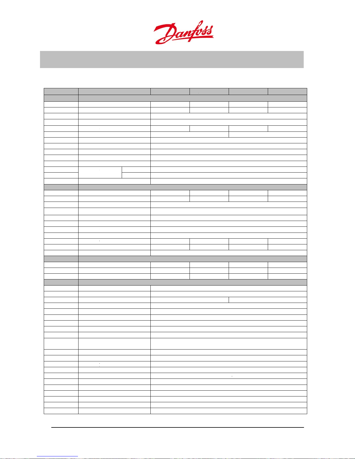
u
T
I
,
p
N
r
t
p
t
g
p
n
c
m
q
u
p
m
D
m
a
v
T
v
T
v
t
u
y
m
o
g
n
n
m
e
h
n
a
a
y
c
p
a
h
)
u
a
w
C
t
n
r
a
v
y
a
n
A
2
020
.
6
9
999
a
X
1
3
b
X
4
%
W
0
m
c
0
0
%
V
D
D
W
a
B
9
s
A
4
4
m
m
m
m
s
s
p
.
±
V
n
g
A
±
10.
ECH
ICAL
DAT
10.1.
|S|
P
V
ac,r
V
ac, min
I
acmax
Cosphi
fr
f
, f
min
max
V
dc,r
V
mppmin Vm
nverte
; V
AC volta
ac
max
ac,r
pmax
Parame
AC
Rated ap
Rated act
Rated ou
Max out
AC curre
Power Fa
Night-ti
Mains fre
Grid freq
Inrush cu
Max out
current
Measure
DC
Nominal
Max reco
Normal o
MPP volt
MPP effic
Max. DC
urn on
urn off
Max inpu
Max. inp
Min. on g
Efficienc
Maximu
CEC effici
EU efficie
Other
Dimensi
Mountin
Weight
Sealing g
Acoustic
Operatio
Nom. te
Storage t
Relative
Protectio
power
Overvolt
Overvolt
Max utilit
Cable ac
Ethernet
RS-485
CAN
PV conne
AC/grid c
Reverse
Ground f
datas
er
arent power
ive power
put voltage
e range (P-N. P-P
ut current
t distortion (THD
tor (cos φ)
e power loss
uency
ency range
rrent
ut fault Val
dur
ents accuracy
C power
mended PV po
perating range D
ge-nominal pow
iency
oltage
oltage
oltage
operating curre
t short circuit cu
rid power
efficiency
ency
ncy
ns
recommendatio
ade
oise level
al temperature r
perature range
mperature
umidity
against excessi
ge category AC
ge category DC
backfeed to PV
es ( conduit knoc
ction
onnection
olarity protectio
ult monitoring
eet
DLX
10
%)
e
tion
er 2
er
t
rent 1
n
nge
e PV
rray
kouts)
.0 UL DL
2
00 VA
00 W
208/240
0/8.8 A
2.59%
AC voltage
2
100 W
25 W
.5 A
1.5 A
7.2 %
6.8 %
6.3 %
720 x 35
22kg / 49l
2 x 3/4” +
2.9 UL
2900 VA
2900 W
208/2
V
+ 10 %, - 12
14.0/12.0 A
< 1
60 H
59.3 – 6
100 mA (rms),
3.14
13
: ± 2.5V, Frequen
3000 W
3750 W
230 - 5
230 - 5
99.9
600
230 V
220 V
13.5 A
16.5 A
7
97.2 %
96.8 %
96.5 %
x 154 mm / 28.3
Wall br
s
NEMA
< 37d
-25 °C....55 °C / -1
-25 °C....40 °C / -1
-25 °C....80 °C / -1
4 to 9
Ye
Class
Class
0.0
2 x1”base / 1 x 3/
1 x RJ
Screw ter
Screw ter
Screw ter
Screw ter
Ye
Ye
DLX 3.8 UL
3800 VA
3800 W
0 V
)
single or split
18.5/16.0 A
1
z
.5Hz
2 A (peak)
A
s
y: ± 0.1 %, Time:
4000 W
5000 W
0 V
0 V
C
C
18.0 A
22.0 A
97.2 %
97.0 %
96.7 %
5 x 13.90 x 6.50 i
cket
3R
(A)
3 °F ....+131 °F
3 °F ....+104 °F
3 °F ....+176 °F
%
B
B
” + 1x1” sides an
45
inals
inals
inals
inals
24k
DLX 4.4 UL
hase
3
36%
30 ms
ches)
/ 55lbs
d back
4400 VA
4400 W
21.5/18.5.
4600 W
5750 W
21.0 A
25.0 A
97.3 %
97.0 %
96.9 %
User G
ide DLX UL series
L00410625-01
9
1

D
d
T
y
a
a
r
m
n
n
n
a
p
a
v
d
f
o
n
u
i
h
vsw
7
e
e
C
e
0
E
s
d
m
n
g
g
c
s
e
d
d
d
v
1
t
a
E
r
g
o
r
e
3
0
t
C
Integral
PV groun
opolog
Performa
Input fe
Cooling c
Function
Safety (p
Islanding
Indirect c
Voltage
surveilla
Insulatio
DC conte
surveilla
Function
EM com
UL mark
Other st
Protecti
C switch
ing
nce monitoring
tures
oncept
l safety
otective class)
detection/ loss o
ntact protectio
agnitude & freq
ce
resistance surve
nt of AC current
ce
l safety
atibility
ing
ndards
e class
mains
ency
llance
Field configurabl
Grap
ical colour displa
Re
erse polarity pr
itch, integral D
EN 61
000-6-2, EN 61
Yes
UL 1
41, IEEE 1547, I
I
High fr
positiv
Ye
for ungrounde
quency transfor
y with 6 touch se
indication, Build-
otection, grou
fuses for strin
and negative
Conve
Clas
Active Frequ
Yes, (Start class
Inclu
Inclu
Inclu
00-6-3, FCC le
C 61000-3-2/1
, positive & nega
er, galvanic isol
nse buttons, 3x L
in Web Server
d fault monito
inputs, field c
rounded PV st
tion
I
ncy Shift
I, grounded)
ed
ed
ed
el B
, IEC 61000-3-
ive grounded
tion
Ds for visual sta
ing, integral D
nfigurable for
ings
/12
us
92
U
ser Guide DLX UL
series L00410625-
01

u
F
1
r
r
r
e
r
t
e
e
e
e
e
t
r
r
e
e
1
r
r
r
e
r
t
e
e
e
e
e
t
r
r
e
e
d
p
e
e
p
e
e
L
412
2
518
0
2608598
L
81226
5
1
212608598
L
E
z
z
E
z
z
X
4
2
0
1
0
0
8
0
8
X
8
6
4
124
0
8
0
8
4
0
0
8
6
4
4
10.2.
Table
VALUE
Vac Ove
high trip
Vac Ove
high trip
Vac Ove
low trip l
Vac Ove
low trip
Vac Und
high trip
Vac Und
high trip
Vac Und
low trip l
Vac Und
low trip
Vac Ove
trip level
Vac Ove
trip time
Vac Und
trip level
Vac Und
trip time
Table
VALUE
Vac Ove
high trip
Vac Ove
high trip
Vac Ove
low trip l
Vac Ove
low trip
Vac Und
high trip
Vac Und
high trip
Vac Und
low trip l
Vac Und
low trip
Vac Ove
trip level
Vac Ove
trip time
Vac Und
trip level
Vac Und
trip time
ield A
0.1: 208Vac Tri
voltage
level
voltage
time
voltage
vel
voltage
ime
rvoltage
level
rvoltage
time
rvoltage
vel
rvoltage
ime
frequency
frequency
r frequency
r frequency
0.2: 240Vac Tri
voltage
level
voltage
time
voltage
vel
voltage
ime
rvoltage
level
rvoltage
time
rvoltage
vel
rvoltage
ime
frequency
frequency
r frequency
r frequency
justab
Details
DEFAU
Details
DEFAU
le Trip
T SETTING
2
7.1 V
0 ms
2
6.3 V
9
0 ms
5.5 V
1
.95 s
1
6.5 V
1
0 ms
.45 Hz
0 ms
.35 Hz
0 ms
T SETTING
2
5.5 V
0 ms
1.5 V
9
0 ms
2
3.7 V
1
.95 s
1
2.5 V
0 ms
.45 Hz
0 ms
.35 Hz
0 ms
evels
MIN. LEV
208.0 V
50 ms
208.0 V
50 ms
185.5 V
50 ms
106.5 V
50 ms
60.00 H
50 ms
59.35 H
50 ms
MIN. LEV
240.0 V
50 ms
240.0 V
50 ms
213.7 V
50 ms
122.5 V
50 ms
60.00 H
50 ms
59.35 H
50 ms
L MA
6
6
L MA
6
6
. LEVEL
2
7.1 V
1
20 ms
2
26.3 V
9
50 ms
2
8.0 V
.95 s
2
8.0 V
1
20 ms
.45 Hz
0 ms
.00 Hz
0 ms
. LEVEL
2
5.5 V
1
20 ms
2
1.5 V
9
50 ms
2
0.0 V
.95 s
0.0 V
1
20 ms
.45 Hz
0 ms
.00 Hz
0 ms
ACCURACY
±2.5V
±30 ms
±2.5V
±30 ms
±2.5V
±30 ms
±2.5V
±30 ms
±0.1%
±30 ms
±0.1%
±30 ms
ACCURACY
±2.5V
±30 ms
±2.5V
±30 ms
±2.5V
±30 ms
±2.5V
±30 ms
±0.1%
±30 ms
±0.1%
±30 ms
User G
ide DLX UL series
L00410625-01
9
3

CERTIFICATE OF COMPLIANCE
Certificate Number
20121008-E357295
Report Reference
E357295-20121004
Issue Date
2012-OCTOBER-08
William R. Carney, Director, North American Certification Programs
UL LLC
Any information and documentation involving UL Mark services are provided on behalf of UL LLC (UL) or any authorized licensee of UL. For questions, please
contact a local UL Customer Service Representative at www.ul.com/contactus
Issued to:
DANFOSS L L C
4401 N BELL SCHOOL RD
LOVES PARK, IL 61111 USA
This is to certify that
representative samples of
STATIC INVERTERS, CONVERTERS AND
ACCESSORIES FOR USE IN INDEPENDENT POWER
SYSTEMS
DLX 2.0 UL, DLX 2.9 UL, DLX 3.8 UL, DLX 4.4 UL
Have been investigated by UL in accordance with the
Standard(s) indicated on this Certificate.
Standard(s) for Safety:
UL 1741, Inverters, Converters, Controllers and
Interconnection System Equipment for Use with Distributed
Energy Resources.
CSA-C22.2 No. 107.1, General Use Power Supplies.
Additional Information:
See the UL Online Certifications Directory at
www.ul.com/database for additional information
Only those products bearing the UL Listing Mark for the US and Canada should be considered as
being covered by UL's Listing and Follow-Up Service meeting the appropriate requirements for US
and Canada.
The UL Listing Mark for the US and Canada generally includes: the UL in a circle symbol with “C” and
“US” identifiers: the word “LISTED”; a control number (may be alphanumeric) assigned by UL;
and the product category name (product identifier) as indicated in the appropriate UL Directory.
Look for the UL Listing Mark on the product.
Page 1 of 1

Danfoss can accept no responsibility for possible errors in catalogues, brochures and other printed material. Danfoss reserves the right to alter its products without notice. This also applies to products
already on order provided that such alterations can be made without subsequential changes being necessary in specifications already agreed.
All trademarks in this material are property of the respective companies. Danfoss and the Danfoss logotype are trademarks of Danfoss A/S. All rights reserved.
Rev. date 2012-07-02 Lit. No. L00410625-01_22
Danfoss Solar Inverters
4401 N. Bell School Rd.
Loves Park, IL 61111
United States
Tel: +1 (815) 639-8600
Fax: +1 (815) 639-8000
www.danfoss.us/solar
Danfoss Solar Inverters A/S
Ulsnaes 1
DK-6300 Graasten
Denmark
Tel: +45 7488 1300
Fax: +45 7488 1301
E-mail: solar-inverters@danfoss.com
www.danfoss.com/solar
 Loading...