

Approval mark
Datasheets
DLE5.7CN Energy-optimized
LBP/MBP R290 115-127V 60Hz
General
Code number 102H3682
Code number (pre-assembled CSIR start equipment) 102H3683
Approvals UL984
Compressors on pallet 100
Compressors on pallet (with CSIR start equipment) 80
Application
Application LBP/MBP
Frequency Hz 50 60
Evaporating temperature °F – -31 to 45
Voltage range V – 95 - 135
Max. condensing temperature continuous (short) °F – 131 (149)
Max. winding temperature continuous (short) °F – 257 (275)
Cooling requirements
Frequency Hz 50 60
Application
90°F – – – S* F2–
100°F – – – S* F
110°F – – – F
Remarks on application: For evaporation temperatures higher than 32 °F do not run
compressor at condensing temperatures higher 122 °F in steady state operation.
* Run capacitor 15 µF compulsory with static cooling (S).
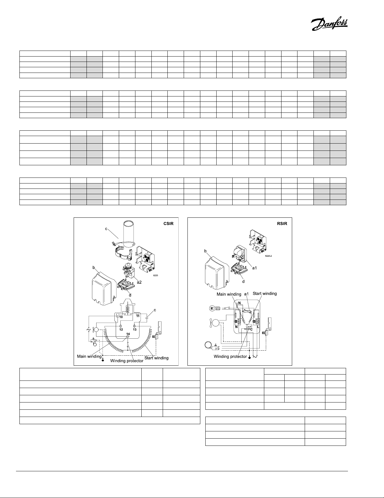
Motor
Motor type CSIR/RSIR/RSCR
LRA (rated after 4 sec. UL984), HST | LST A 21.1 17.6
Cut in Current, HST | LST A 21.1 25.4
Resistance, main | start winding (77°F) Ω 2.7 6.4
LBP MBP HBP LBP MBP HBP
2
2F2
Application
DLE5.7CN
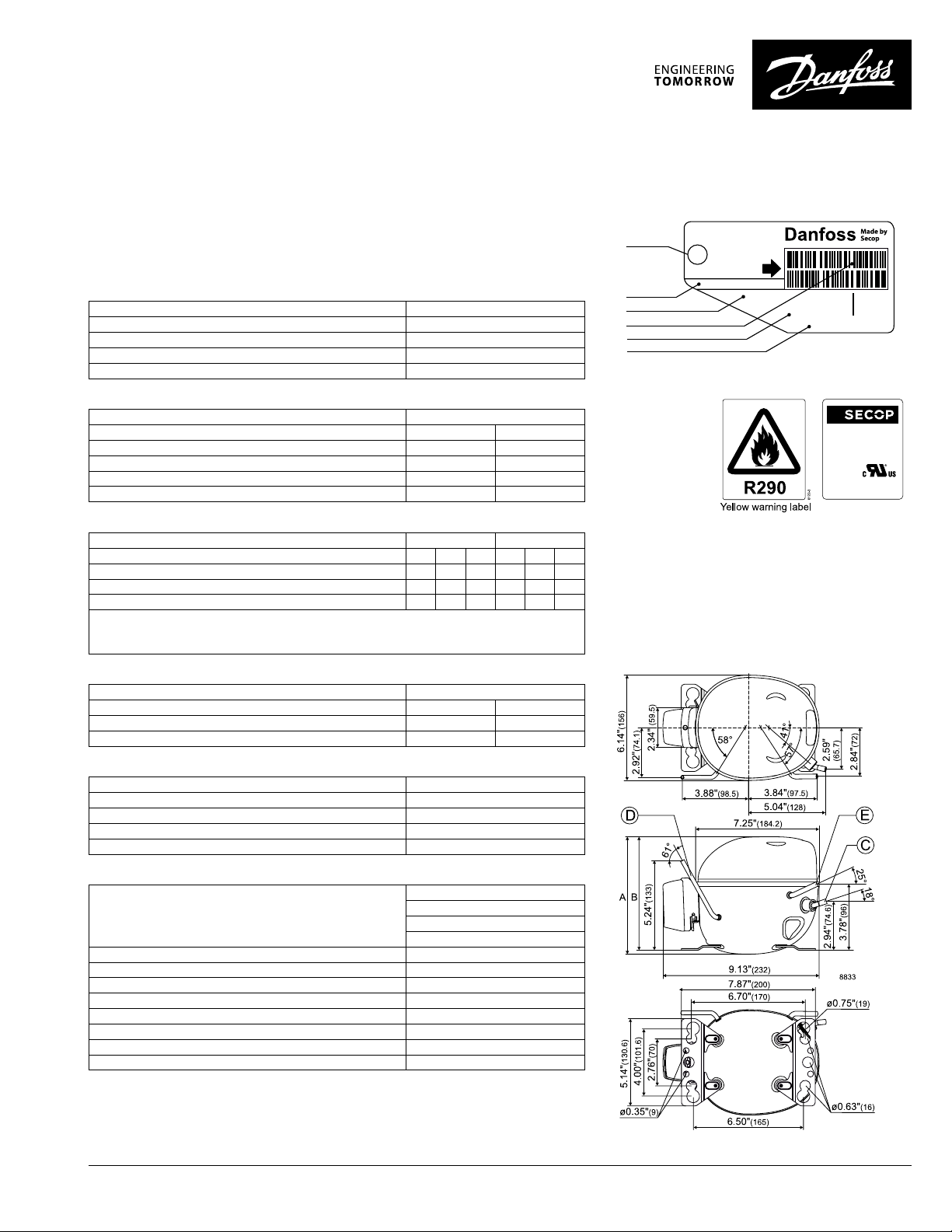
SUCTION
Red stripe
Approvals
Barcode on white background
Green background
Country of origin or manufacturer
S = Static cooling normally sufcient
O = Oil cooling
F
= Fan cooling 1.5 m/s
1
–
(compressor compartment temperature
–
equal to ambient temperature)
F2 = Fan cooling 3.0 m/s necessary
SG = Suction gas cooling normally sufcent
– = not applicable in this area
R290
serial number
3682
Made by Secop
DLE5.7CN
115-127V-60Hz
1PH
THERMALLY
PROTECTED
102H
Design
Displacement cu.in 0.35
Oil quantity (type) .oz. 7.8 (polyolester)
Maximum refrigerant charge oz. 5.3
Free gas volume in compressor .oz. 49.5
Weight without electrical equipment lbs. 18.1
Dimensions
Height inch A 6.90
B 6.64
B1 –
B2 –
Suction connector location, I.D. in. | angle C 0.320-0.327 | 18°
material | comment Copper | Rubber plug
Process connector location, I.D. in. | angle D 0.252-0.259 | 60°
material | comment Copper | Rubber plug
Discharge connector location, I.D. in. | angle E 0.252-0.259 | 25°
material | comment Copper | Rubber plug
Oil cooler connector location, I.D. in. | angle F –
material | comment –
DEHC.ED.100A1.22
© Danfoss | DCS (CC) | 2015.10 | 1
ASHRAE LBP 115V, 60Hz, fan cooling F
Evap. temp. in °F -49 -40 -30 -20 -13 -10 0 10 14 20 30 32 40 41 45 50 59
2
Capacity in BTU/h 681 914 1100 1187 1507 1882 2050 2321 2830 2941 3419 3483 3746
Power cons. in W 179 206 225 233 260 286 296 311 334 338 355 357 364
Current cons. in A 2.60 2.74 2.85 2.90 3.08 3.27 3.34 3.45 3.63 3.67 3.80 3.82 3.88
EER in BTU/Wh 3.81 4.44 4.90 5.10 5.80 6.59 6.93 7.47 8.48 8.70 9.64 9.77 10.3
ASHRAE MBP/HBP 115V, 60Hz, fan cooling F
Evap. temp. in °F -49 -40 -30 -20 -13 -10 0 10 14 20 30 32 40 41 45 50 59
2
Capacity in BTU/h 609 817 983 1060 1345 1680 1828 2069 2521 2619 3041 3097 3329
Power cons. in W 177 204 222 230 257 283 293 307 330 334 350 352 359
Current cons. in A 2.60 2.74 2.85 2.90 3.08 3.27 3.34 3.45 3.63 3.67 3.80 3.82 3.88
EER in BTU/Wh 3.44 4.01 4.42 4.60 5.24 5.94 6.25 6.73 7.64 7.84 8.68 8.79 9.26
EN 12900 LBP 115V, 60Hz, fan cooling F
Evap. temp. in °F -49 -40 -30 -20 -13 -10 0 10 14 20 30 32 40 41 45 50 59
2
Capacity in W 207 269 321 345 435 541 588 665 809 841 976 994 1068
Power cons. in W 181 202 218 224 246 267 275 287 306 309 322 324 330
Current cons. in A 2.58 2.68 2.75 2.79 2.92 3.05 3.11 3.18 3.31 3.33 3.42 3.43 3.47
COP in W/W 1.14 1.33 1.47 1.54 1.77 2.03 2.14 2.32 2.65 2.72 3.03 3.07 3.24
EN 12900 MBP 115V, 60Hz, fan cooling F
Evap. temp. in °F -49 -40 -30 -20 -13 -10 0 10 14 20 30 32 40 41 45 50 59
2
Capacity in W 200 268 322 348 442 552 601 680 829 862 1002 1021 1098
Power cons. in W 179 206 225 233 260 286 296 311 334 338 355 357 364
Current cons. in A 2.60 2.74 2.85 2.90 3.08 3.27 3.34 3.45 3.63 3.67 3.80 3.82 3.88
COP in W/W 1.12 1.30 1.44 1.49 1.70 1.93 2.03 2.19 2.48 2.55 2.83 2.86 3.02
Accessories for DLE5.7CN Figure Code number Test conditions
)
ePTC starting device 1/4 in. spade connectors a1 103N0058 *
Condensing temperature 104°F 113°F
Starting relay 1/4 in. spade connectors a2 117U7011 Ambient temperature 90°F 90°F
Start. capacitor 240 µF 1/4 in. spade connectors c 117U5023 Suction gas temperature 68°F 68°F
Cover b 103N0492 Liquid temperature no subcooling
EN 12900
LBP MBP
ASHRAE
LBP MBP
130°F 130°F
90°F 90°F
90°F 95°F
90°F 115°F
Cord relief d 103N1010
)
Remarks: RSIR and RSCR option available in 4th quarter 2015 Mounting accessories Code number
*
Bolt joint for one comp. Ø: 3/4 in. 118-1949
Bolt joint for one comp. Ø: 5/8 in. 118-1946
Snap-on for one comp. Ø: 5/8 in. 118-1947
2 | © Danfoss | DCS (CC) | 2015.10
DEHC.ED.100A1.22
ASHRAE LBP 115V, 60Hz, RC 15 µF, ePTC consumption incl., fan cooling F
Danf
already on order pro
All trademarks in this material are property of the respec
Evap. temp. in °F -49 -40 -30 -20 -13 -10 0 10 14 20 30 32 40 41 45 50 59
2
Capacity in BTU/h 686 921 1111 1199 1524 1905 2074 2347 2858 2969 3445 3508 3769
Power cons. in W 170 195 212 219 244 268 278 291 312 316 332 333 340
Current cons. in A 2.47 2.59 2.69 2.74 2.90 3.07 3.13 3.24 3.40 3.43 3.56 3.57 3.63
EER in BTU/Wh 4.03 4.74 5.24 5.46 6.24 7.10 7.47 8.06 9.15 9.38 10.4 10.5 11.1
ASHRAE MBP/HBP 115V, 60Hz, RC 15 µF, ePTC consumption incl., fan cooling F
Evap. temp. in °F -49 -40 -30 -20 -13 -10 0 10 14 20 30 32 40 41 45 50 59
2
Capacity in BTU/h 613 824 993 1071 1361 1699 1850 2092 2545 2643 3064 3119 3350
Power cons. in W 168 193 210 217 242 265 275 288 309 313 327 329 336
Current cons. in A 2.47 2.59 2.69 2.74 2.9 3.07 3.13 3.24 3.40 3.43 3.56 3.57 3.63
EER in BTU/Wh 3.64 4.28 4.73 4.93 5.63 6.40 6.74 7.27 8.24 8.45 9.36 9.48 9.97
EN 12900 LBP 115V, 60Hz, RC 15 µF, ePTC consumption incl., fan cooling F
Evap. temp. in °F -49 -40 -30 -20 -13 -10 0 10 14 20 30 32 40 41 45 50 59
2
Capacity in W 209 272 324 348 440 547 595 672 817 849 983 1001 1074
Power cons. in W 172 191 205 211 231 251 258 269 286 289 301 303 308
Current cons. in A 2.45 2.53 2.60 2.63 2.74 2.86 2.91 2.98 3.10 3.12 3.20 3.21 3.24
COP in W/W 1.21 1.42 1.58 1.65 1.90 2.18 2.30 2.50 2.86 2.93 3.26 3.31 3.49
EN 12900 MBP 115V, 60Hz, RC 15 µF, ePTC consumption incl., fan cooling F
Evap. temp. in °F -49 -40 -30 -20 -13 -10 0 10 14 20 30 32 40 41 45 50 59
2
Capacity in W 201 270 326 351 447 558 608 688 838 870 1009 1028 1104
Power cons. in W 170 195 212 219 244 268 278 291 312 316 332 333 340
Current cons. in A 2.47 2.59 2.69 2.74 2.90 3.07 3.13 3.24 3.40 3.43 3.56 3.57 3.63
COP in W/W 1.18 1.39 1.54 1.60 1.83 2.08 2.19 2.36 2.68 2.75 3.05 3.08 3.25
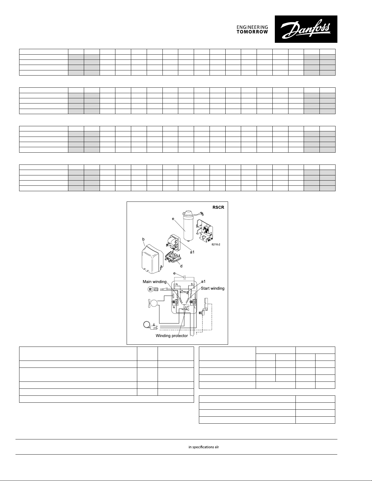
Accessories for DLE5.7CN Figure Code number Test conditions
ePTC starting device 1/4 in. spade connectors a1 103N0058 *
Run capacitor 15 µF 1/4 in. spade connectors
(optional) Suction gas temperature 68°F 68°F
Cover b 103N0492 Liquid temperature no subcooling
Cord relief d 103N1010
)
Remarks: RSIR and RSCR option available in 4th quarter 2015 Mounting accessories Code number
*
oss can accept no responsibility for possible errors in catalogues, brochures and other printed material. Danfoss reserves the right to alter its products without notice. This also applies to products
vided that such alterations can be made without subsequential changes being necessary eady agreed.
3 | © Danfoss | DCS (CC) | 2015.10
)
Condensing temperature 104°F 113°F
Ambient temperature 90°F 90°F
e 117-7118 *
)
Bolt joint for one comp. Ø: 3/4 in. 118-1949
Bolt joint for one comp. Ø: 5/8 in. 118-1946
Snap-on for one comp. Ø: 5/8 in. 118-1947
tive companies. Danfoss and the Danfoss logotype are trademarks of Danfoss A/S. All rights reserved.
EN 12900
LBP MBP
ASHRAE
LBP MBP
130°F 130°F
90°F 90°F
90°F 95°F
90°F 115°F
DEHC.ED.100A1.22
 Loading...