

Page 1
Application guidelines
DC Compressors
DL19H / DL22H / DL30H
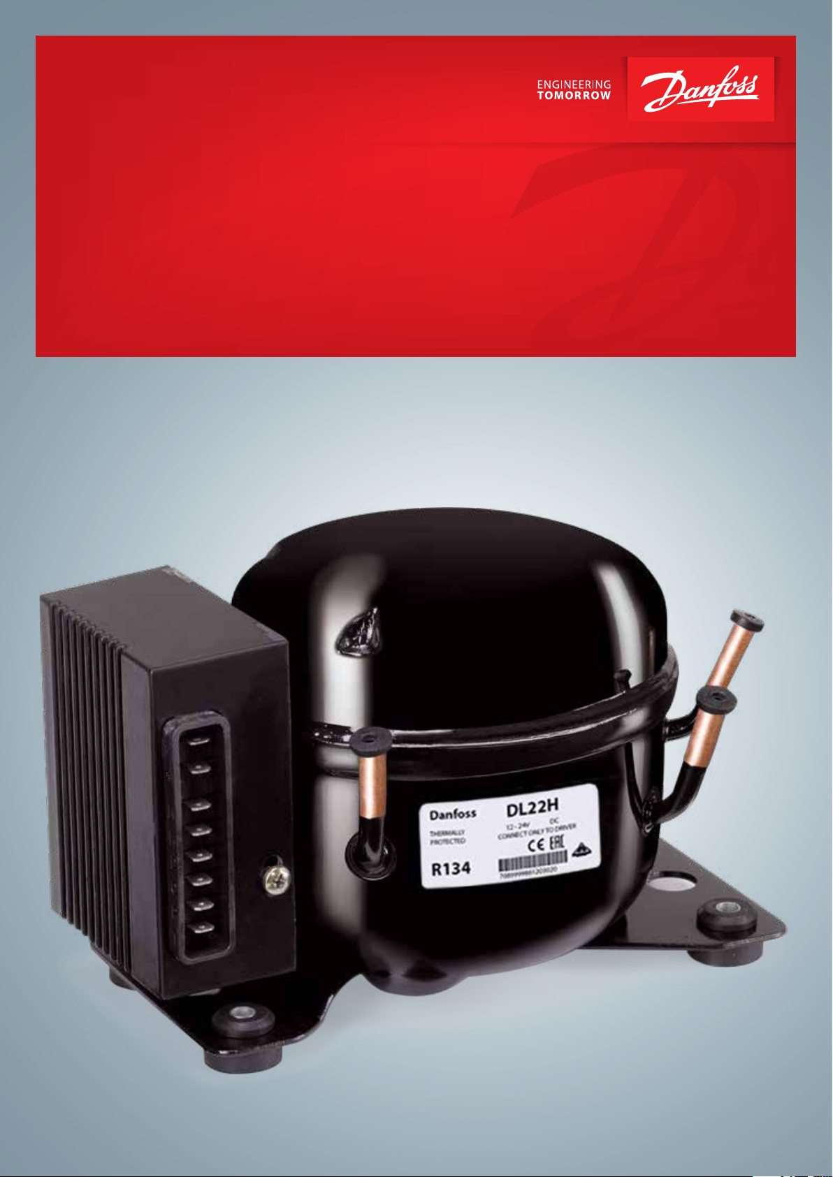
Compressors for mobile applications
12 - 24V Direct Current Compressor
www.danfoss.com
Page 2

Page 3

Application Guidelines
Content
DL compressors ...................................................................................................................................4
Compressor Overview .............................................................................................................................................................................4
Technical specification ............................................................................................................................................................................4
Performance data ................................................................................................................................5
Operating envelope ............................................................................................................................6
Electronic Driver controlled through resistance ...............................................................................7
General rules and wiring connections ...............................................................................................................................................7
Voltage drop in the power leads ..........................................................................................................................................................7
Terminal lay out wiring Diagram..........................................................................................................................................................7
Operating voltage .....................................................................................................................................................................................8
Battery protection system ......................................................................................................................................................................8
Temperature Switch .................................................................................................................................................................................8
Speed determination ..............................................................................................................................................................................9
Protections and alarms ............................................................................................................................................................................9
Ordering and packaging .................................................................................................................. 10
3BC346145660120en-000101
Page 4
202
16.5
Application Guidelines
DL compressors
Compressor Overview
Technical specification
Many vehicles for transportation of goods or
recreation, such as trucks, caravans, boats, cars,
etc. are often equipped with cooling appliances.
These compressors are designed to operate
silently, efficiently and reliably even up to angles
of tilt of 30º, working with refrigerant R134a.
The compressors for such mobile applications
must be designed to operate from a low voltage
DC power supply. These compressors must also
be compact in their dimensions, highly reliable
and yield high performances.
The DL series of compressors are not designed for
off-road applications. Special approval is required
by Danfoss Commercial Compressors for this type
of application. The maximum tilt angle allowed in
DL compressors (stopped or running) is 30º.
DL19H, DL22H and DL30H are the answer to the
users’ needs requiring comfort and reliability in
their travelling, either on holidays, at work or in
any other circumstance where Direct current is
DL19H, DL22H and DL30H can be powered at any
voltage within the 12 to 24V DC range, and are
designed for capillary tube expansion.
required for cooling.
Refrigerant R134a *
Oil type / charge ISO VG 15 ESTER / 120cm
Expansion capilary tube
Application LBP/ MBP / HBP
Evaporation temperature range -35ºC to +10ºC.
Condensation temperature range up to 65ºC (Pull-down peak: 70ºC).
Ambient temperature range -10 to 43ºC **
voltage range DC 9.6 - 17 / 21.3 - 31.5 VDC
Motor speed range 2000 - 3500 rpm
Consumption of the electronic driver when the compressor is stopped 0.5W
Comp. dispalcement DL19H/DL22H/DL30H 1.9cm3 / 2.2cm3 / 3cm
Weight DL19H/DL22H/DL30H+ Electronic unit 3.9kg / 4.2kg /4.2 kg + 0.2 kg
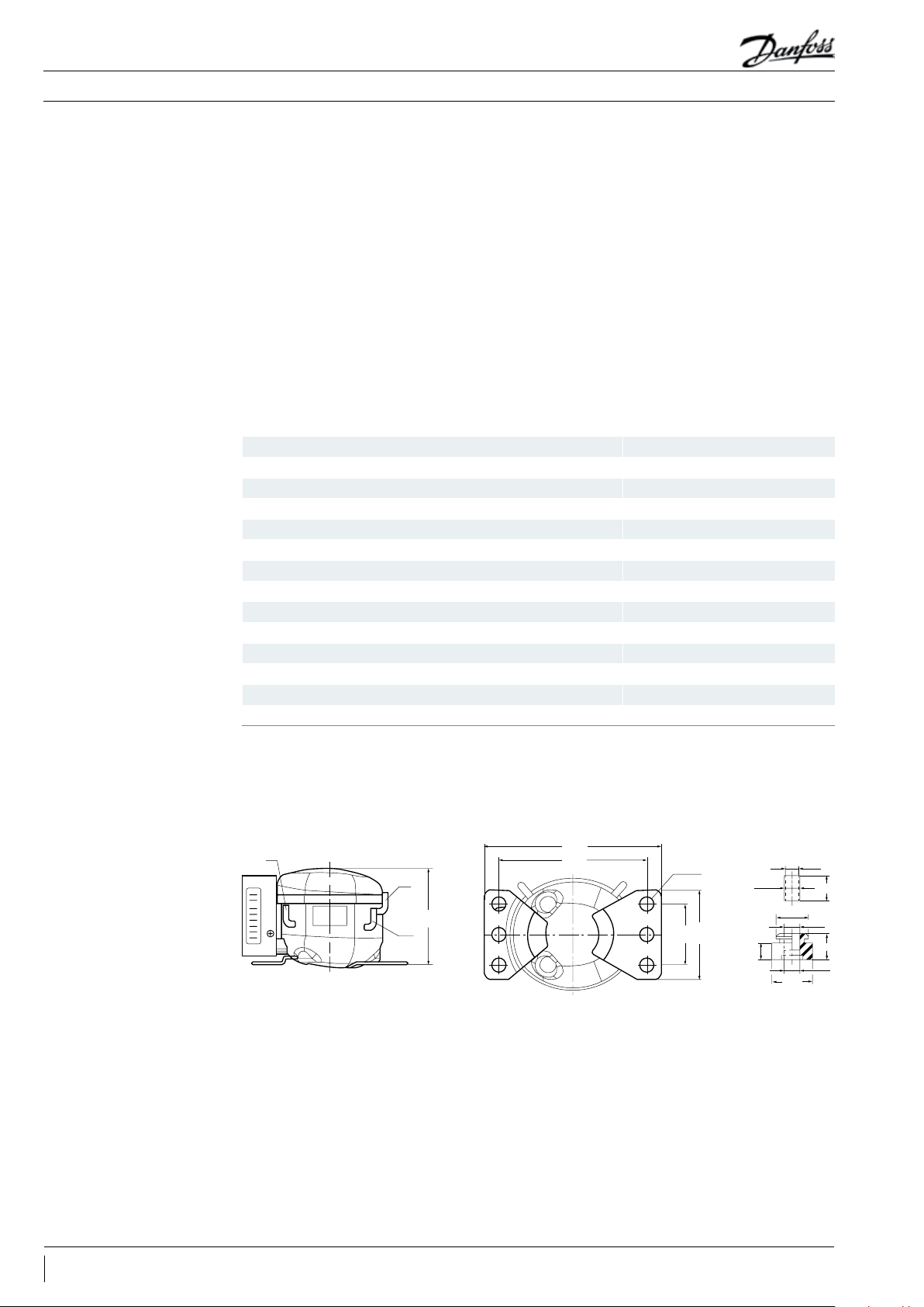
Suction connector I.D. 6.2 mm (1)
Service connector I.D. 6.2 mm (2)
Discharge connector I.D. 4.9 mm (3)
* Compatible refriger. R1234yf
** In case of ambi ent temperature lower than 0 ºC. an oil heate r will be needed.
3
3
Fixings and Silent blocks (Mounting Accessories) Standard
6 holes Ø16
1
1. Suction 6.2 mm
2. Service 6 .2 mm
3. Discharge 4.9 mm
4. 6 holes Ø16 (170 X 70 net)
170
4
3
129
2
70
102
(170 X 70 net)
Ø10.2
Ø21
11
Ø26
Ø8.6
Ø10.5
17
Ø9.8
4 BC346145660120en-000101
Page 5

Application Guidelines
Performance data
Table 1: Cooling Capacity [W] ASHRAE
Type / Code rpm
2000 10 16 26 29 37 52 70 91 114 141 154 171
DL19H /
123F1905
DL22H /
123 F190 6
DL30H /
123 F1907
2500 13 22 35 40 50 69 91 115 144 174 190 209
3000 15 25 38 44 57 79 103 135 168 208 227 253
3500 16 30 50 57 73 100 131 167 208 252 273 301
2000 14 22 34 38 49 66 87 110 138 169 183 201
2500 17 27 40 45 57 78 104 133 165 202 220 243
3000 22 33 48 54 68 93 123 158 196 241 262 289
3500 28 41 59 66 83 113 148 190 236 288 314 348
2000 21 30 45 49 64 88 116 149 187 229 103 276
2500 24 37 56 63 79 108 144 184 230 283 306 340
3500 34 53 79 89 110 147 188 235 287 344 369 407
-35 -30 -25 -23. 3 -20 -15 -10 -5 0 5 7. 2 10
Table 2: Power consumption [W] ASHRAE
Type / Code rpm
DL19H /
123F1905
DL22H /
123 F190 6
DL30H /
123 F1907
2000 0.58 0.75 0.99 1.08 1.26 1.56 1.88 2.22 2.56 2.91 3.07 3.27
2500 0.56 0.80 1.07 1.16 1.35 1.65 1.95 2.25 2.56 2.87 3.01 3.18
3500 0.54 0.83 1.12 1.21 1.4 1. 68 1.95 2.22 2.48 2.74 2.85 2.99
2000 0.66 0.85 1.08 1.16 1.33 1.6 0 1.89 2.18 2.49 2.80 2.95 3 .13
2500 0.67 0.86 1.10 1.19 1.37 1.66 1.96 2.25 2. 55 2.84 2.97 3.13
3500 0.80 0.94 1.15 1.23 1. 39 1.65 1.93 2.21 2.50 2.78 2.97 3.07
2000 0.78 0.93 1.14 1. 22 1.38 1.64 1.90 2.17 2.43 2.69 2.80 2.94
2500 0.74 0.93 1.17 1.26 1.43 1.71 1.99 2.26 2.53 2.79 2.9 3.04
3500 0.77 0.96 1.17 1.24 1.39 1.62 1.87 2.12 2.39 2.66 2.79 2.95
-35 -30 -25 -23. 3 -20 -15 -10 -5 0 5 7. 2 10
Cooling Capacity [W] ASHRAE ºC
Power consumption [W] ASHRAE ºC
Table 3: COP [W/W] ASHRAE
Type / Code rpm
DL19H /
123F1905
DL22H /
123 F190 6
DL30H /
123 F1907
2000 0.58 0.75 0.99 1.08 1.26 1.56 1. 88 2.22 2.56 2.91 3.07 3.27
2500 0.56 0.80 1.07 1.16 1. 35 1.65 1.95 2.25 2.56 2.87 3.01 3.18
3500 0.54 0.83 1.12 1.21 1.4 1. 68 1.95 2.22 2.48 2.74 2.85 2.99
2000 0.66 0.85 1.08 1.16 1.33 1.6 0 1.89 2.18 2.49 2.80 2.95 3 .13
2500 0.67 0.86 1.10 1.19 1.37 1.66 1.96 2.25 2. 55 2.84 2.97 3.13
3500 0.80 0.94 1.15 1.23 1. 39 1.65 1.93 2.21 2.50 2.78 2.97 3.07
2000 0.78 0.93 1.14 1. 22 1.38 1.64 1.90 2.17 2.43 2.69 2.80 2.94
2500 0.74 0.93 1.17 1.26 1.43 1.71 1.99 2.26 2.53 2.79 2.9 3.04
3500 0.77 0.96 1.17 1.24 1.39 1.62 1.87 2.12 2.39 2.66 2.79 2.95
COP [W/W] ASHRAE ºC
-35 -30 -25 -23. 3 -20 -15 -10 -5 0 5 7. 2 10
5BC346145660120en-000101
Page 6

Application Guidelines
Operating envelope
6 BC346145660120en-000101
Page 7

Application Guidelines
Electronic Driver controlled through resistance
General rules and wiring connections
Voltage drop in the power leads
DL series must always be powered through the
dedicated electronic driver, which is supplied
with the compressor as a separate device.
• Never connect the compressor’s hermetic pins
(fusite) to the terminals of a battery or any
other dc or ac source directly.
• Do not try to fit an electronic driver different
than the electronic driver supplied with the
compressor. the compressor will not operate
and irreversible damage may occur.
the power input terminals of the electronic
driver
• “-“ Power input terminal of the electronic driver
should be connected to the chassis of the
vehicle as well as the appliance frame
• A fuse must be placed between the “+” pole
of the battery or dc power supply and the “+”
power input terminal of the electronic driver:
- 12V systems: 12A fuse
- 24V systems: 7.5A fuse
• Always respect the polarity of the battery with
To avoid excessive voltage drop in the leads, their length and cross section must be related to the
voltage supply as indicated in Table below.
Table 4
Cross section Rated Operating Range
2
mm
2.5 2.5 5
4 4 8
6 6 12
10 10 20
12V 24V
Length (m)
Terminal lay out Wiring Diagram
The electronic driver features a terminal board where all connections are made. The terminal lay out is
described in the wiring diagram.
34
2
+
–
+
6
–
+
5
–
–
+
F+
F–
D
1
C
7
8
P
T
Legend
1 Electronic driver
2 Battery
3 Fuse
4 Main switch
5 External Fan*
6 LED
7 Thermostat
8 Resistor (speed selection)
9 Resistor (battery protection )
9
* The positive side of the fan is connected to the (F +) end of the controller, and the negative terminal of the controller is connected to the
(F-) terminal of the controller. A terminal of the controller (F +) and (F-) can be connected with a 12V DC fan The When the input voltage of
the controller exceeds 12V, the output value between the terminals (F +) and (F-) is always kept at 12V.
Regardless of whether the input voltage system is 12V or 24V, the fan must be a 12V DC fan. B, the controller can continue to output 0.5A
fan drive capability.
7BC346145660120en-000101
Page 8

Application Guidelines
Electronic Driver controlled through resistance
Operating voltage
Battery protection system
DL series are designed to operate in a wide range of DC voltages, supplied either by a battery or by
any other kind of filtered DC power supply.
DC voltage supply allowed: 9.6V to 31.5V. Controller itself detect if is connected to 12V or 24V.
Table 5: Operating Voltage Setting Table
External
resistance
KΩ V V V V V V
0 9.6 10.9 17.0 21.3 22.7 31.5
1.6 9.7 11.0 17.0 21.5 22.9 31.5
2.4 9.9 11.1 17.0 21.8 23.2 31.5
3.6 10.0 11.3 17.0 22.0 23.4 31.5
4.7 10.1 11.4 17.0 22.3 23.7 31.5
6.2 10.2 11.5 17.0 22.5 23.9 31.5
8.2 10.4 11.7 17.0 22.8 24.2 31.5
11 10.5 11.8 17.0 23.0 24.5 31.5
14 10.6 11.9 17.0 23.3 24.7 31.5
18 10.8 12.0 17.0 23.6 25.0 31.5
24 10.9 12.2 17.0 23.8 25.2 31.5
33 11.0 12.3 17.0 24.1 25.5 31.5
47 11.1 12.4 17.0 24.3 25.7 31.5
82 11.3 12.5 17.0 24.6 26.0 31.5
220 9.6 10.9 17.0 21.3 22.7 31.5
12V Stop
value
12V Boot
value
12V High pressure
stop value
24V Stop
value
24V Boot
value
24V High pressure
stop value
There is a protection system for the battery that prevents the compressor from operating if the
available voltage becomes too low. The electronic driver will start and stop the compressor as needed
by detection of the voltage between the input terminals (+) and (-) to protect the different power
supply batteries.
Temperature Switch
The recommended standard battery protection values are listed in table 6. Other voltage can be set by
adjusting the controller terminal (C) and (P) connection resistance (9), the specific value of Table 5.
Table 6: Limits of battery protection parameters
12V Cut-out 12V Cut-in 24V Cut-out 24V Cut-in
V V V V
10.4 11.7 22.8 24.2
The temperature switch (7) e.g. mechanical or electronic thermostat is connected to C and T pins and
determine compressor ON and OFF operation.
8 BC346145660120en-000101
Page 9

Application Guidelines
Electronic Driver controlled through resistance
Speed determination
Protections and alarms
If there is no resistor between C an T pins compressor running speed will be 2000rpm. Table 3 shows
the compressor running speed according to the resistance value connected between pins C and T.
Table 7
Compressor speed C/T Resistance C/T Current
rpm Ω mA
2000 0 5
2100 51 4.8
2200 100 4.6
2300 150 4.4
2400 200 4.2
2500 277 4
2600 330 3.8
2700 400 3.6
2800 490 3.4
2900 586 3.2
3000 692 3
3100 816 2.8
3200 963 2.6
3300 1137 2.4
3400 1331 2.2
3500 1523 2
DL series are electronically protected against a number of possible malfunctions and failures. As
shown in Terminal lay out Wiring Diagram:
• The controller terminal (+) and (D) can be connected between a 10mA LED (6) for the display fault,
LED anode connected to the controller (+) side, the cathode connected to the controller (D) end.
• When the failure occurs, LED every 3 seconds for the cycle, continuous flash in each cycle, according
to different failures flash different times, each flashing for 0.4 seconds, continuous flashing for 3.2
minutes. The number of specific codes and blinks is shown in Table 8.
Table 8: Alarm codification
No. of blinks Fault type
1 Voltage fault - The input voltage is outside the set range
2 Fan current fault - fan current output current greater than 1A
3 Compressor start fault - compressor motor stall or system pressure too large
4 Compressor minimum speed fault - The compressor is overloaded or the motor speed is too small.
5 Controller temperature fault - controller housing temperature too high (> 85 ° C)
6 Controller hardware failure - The controller has detected an abnormal parameter
9BC346145660120en-000101
Page 10

Application Guidelines
Ordering and packaging
Compressors are packed in industrial pack on polyester trays (25pcs each) on the pallet.Packaging and Ordering
Model
DL19H including electronic driver 25 6 150 1135 830 123F1905
DL22H including electronic driver 25 6 150 1135 830 123F1906
DL30H including electronic driver 25 6 150 1135 830 123F1907
Qty/Level Nb of levels Qty/Pallet Length Wight
Industrial pack Pallet dimensions (mm)
code
10 BC346145660120en-000101
Page 11

Page 12

Danfoss Commercial Compressors
Danfoss Inverter Scrolls
is a worldwide manufacturer of compressors and condensing units for refrigeration and HVAC applications. With a wide range
of high quality and innovative products we help your company to find the best possible energy efficient solution that respects
the environment and reduces total life cycle costs.
We have 40 years of experience within the development of hermetic compressors which has brought us amongst the global
leaders in our business, and positioned us as distinct variable speed technology specialists. Today we operate from engineering
and manufacturing facilities spanning across three continents.
Danfoss Turbocor Compressors
Danfoss Scrolls
Danfoss Optyma Condensing Units
Danfoss Maneurop Reciprocating Compressors
Danfoss Light Commercial Refrigeration
Compressors
Our products can be found in a variety of applications such as rooftops, chillers, residential air conditioners,
heatpumps, coldrooms, supermarkets, milk tank cooling and industrial cooling processes.
http://cc.danfoss.com
Danfoss Commercial Compressors, BP 331, 01603 Trévoux Cedex, France | +334 74 00 28 29
BC346145660120en-000101 © Danfoss | DCS (CC) | 2020.06
 Loading...