

Page 1

Installation instruc-
tions
DHP-S&DP
VMIFJ102
Page 2

If these instructions are not followed during installation and service, Danfoss A/Sliability according to the applicable warranty is not
binding. Danfoss A/S retains the right to make changes to components and specifications without prior notice.
© 2010 Copyright Danfoss A/S.
The Swedish language is used for the original instructions. Other
languages are a translation of original instructions.
(Directive 2006/42/EG)
Page 3

Contents
1 About the instructions..................................................................... 3
1.1
Introduction..................................................................................... 3
1.2 Symbols............................................................................................. 3
1.3 Terminology..................................................................................... 3
2 Important information..................................................................... 4
2.1 Refrigerant
........................................................................................ 4
2.2 Noise and vibrations..................................................................... 5
3 Heat pump information................................................................... 9
3.1 Dimensions and components................................................... 9
3.2 Pipe connections......................................................................... 10
3.3 Required service space.............................................................. 10
3.4 Technical data............................................................................... 11
4 Drilling holes for brine pipes....................................................... 13
5 Unpacking and installation.......................................................... 14
5.1 Setting up....................................................................................... 14
5.2 Removing the front cover......................................................... 14
6 Piping installation........................................................................... 16
6.1 Safety valve.................................................................................... 16
6.2 Heating system supply pipe and return pipe.................... 16
6.3 System suggestion...................................................................... 17
7 Electrical Installation...................................................................... 18
7.1 Electrical connection.................................................................. 18
7.2 Connecting pump hot gas....................................................... 18
7.3 Connecting sensor for outside temperature..................... 19
7.4 Connecting hot water sensor.................................................. 19
7.5 Connecting sensor for system supply temperature........ 19
7.6 Connecting exchange valve for hot water......................... 19
7.7 Connecting room sensor (option)......................................... 19
7.8 Connecting pressure and flow sensor (option)................ 19
7.9 Connecting start and stop auxiliary heater........................ 19
7.10 Connecting control signal for auxiliary heater............... 19
7.11 Conversion table for sensors................................................. 19
8 Test operation................................................................................... 21
8.1 Installation checklist................................................................... 21
8.2 Manual test.................................................................................... 22
9 Start up................................................................................................ 25
9.1 Adaptation to the heating system......................................... 25
10 Installing the front cover............................................................ 26
11 Menu information......................................................................... 27
11.1 SERVICE menu............................................................................ 28
11.2 Important parameters............................................................. 36
12 References....................................................................................... 41
VMIFJ102 – 1
Page 4

Page 5

1 About the instructions
1.1 Introduction
The installation instructions start by describing heat pump data. The installation instructions later give instructions
in a logical order covering unpacking, installation procedure, and checking the installation.
References to chapters and sections within the instructions are in italics, e.g.: About the instructions.
References to menu options in the heat pump’s control system are in upper case, e.g.: INFORMATION ->OPERAT. ->
AUTO.
All figures in the instructions are numbered to help installers and service technicians refer to them easily.
1.2 Symbols
The instructions contain different warning symbols, which, together with text, indicate to the user that there are risks
involved with actions to be taken.
The symbols are displayed to the left of the text and three different symbols are used to indicate the degree of danger:
DANGER! Hazardous electrical voltage!Indicates an immediate danger that leads to fatal or serious injury if
necessary measures are not taken.
Warning! Risk of personal injury!Indicates a possible danger that can lead to fatal or serious injury if necessary
measures are not taken.
Caution! Risk of installation damage. Indicates a possible hazard that can lead to item damage if necessary
measures are not taken.
A fourth symbol is used to give practical information or tips on how to perform a procedure.
Note! Information regarding making the handling of the installation easier or a possible operational technical
disadvantage.
1.3 Terminology
The instructions contain terms throughout that designate components and functions. The table lists the most common terms that are used in the instructions.
Table 1. Terminology
Term Meaning
Heating system The circuit that generates heat to the property or to the water heater.
Supply line The heating system’s supply line with flow direction from the heat pump to radiators/
under floor heating or water heater.
Return line The heating system’s return line with flow direction from radiators/under floor heating or
water heater to the heat pump.
Circulation pump Circulation pump for heating system.
Refrigerant circuit The energy carrying circuit between the outdoor air and heating system.
Refrigerant The gas/liquid that circulates in the refrigerant circuit.
Installation instructions VMIFJ102 – 3
Page 6
4 – Installation instructions
VMIFJ102
2 Important information
Caution! The heat pump must be located in a frost-free environment!
Caution! The installation may only be commissioned if the heating system is filled and bled. Otherwise
the circulation pump can be damaged.
Caution! If the electrician wishes to test his connections before the above is carried out, this should only
done when it has been checked that the heat pump, the electric boiler, the compressor and the heat
shields are disconnected.
Caution! When filling the coolant system the coolant pump must be operating but one must ensure that
the compressor and the heat transfer pump cannot start.
The system can be considered maintenance free but certain checks are necessary.
Before changing the control computer’s settings, first find out what these changes mean.
Contact your installer for any service work.
This appliance can be used by children aged from 8 years and above and persons with reduced
physical, sensory or mental capabilities or lack of experience and knowledge if they have been given
supervision or instruction concerning use of the appliance in a safe way and understand the hazards
involved. Cleaning and user maintenance shall not be made by children without supervision.
Note! Children are not permitted to play with the apparatus.
2.1 Refrigerant
The heat pump’s cooling system (refrigerant circuit) is filled with R410A refrigerant.
Caution! Work on the refrigerant circuit must only be carried out by a certified engineer!
Caution! Fire risk R4
10A is not combustible or explosive in normal conditions.
Toxicity
In normal use and normal conditions the refrigerant has low toxicity. However, although the toxicity of the refrig‐
erant is low, it can cause injury (or be highly dangerous) in abnormal circumstances or where deliberately abused.
The refrigerant vapour is many times heavier than air and in enclosed spaces, below the level of the door for
example, and in the event of leakage, large concentrations can occur with the risk of suffocation because of lack
of oxygen. Spaces in which heavy vapour can collect below the level of the air must therefore be well ventilated.
Note! This appliance is intended to be used by expert or trained users in shops, in light industry and on
farms or commercial use by lay persons.
Only spare parts approved by us may be used in this appliance.
Caution! The power supply must be disconnected during service and before changing parts in the
appliance.
Page 7

Warning! Risk of personal injury! Refrigerant exposed to a naked flame creates a poisonous irritating gas.
This gas can be detected by its odour even at concentrations below its permitted levels. Evacuate the area
until it has been sufficiently ventilated.
Warning! Risk of personal injury! Anyone with symptoms of poisoning from the vapour must immediately
move or be moved into the fresh air.
Work on the refrigerant circuit
When repairing the refrigerant circuit, the refrigerant must not be released from the heat pump – it must be destroyed
at a special plant. Draining and refilling must only be carried out using new refrigerant (for the amount of refrigerant
see manufacturer’s plate) through the service valves. Filling with refrigerant other than R410A voids all guarantees from Thermia Värme AB, unless this new refrigerant has been approved in writing as an alternative refrigerant
together with other corrective action.
Scrapping
When the heat pump is to be scrapped the refrigerant must be extracted for disposal. The local regulations for
treatment of refrigerant must be followed. See the relevant Swedish Environmental Protection Agency refrigerant
statutes.
2.2 Noise and vibrations
2.2.1 Flexible hoses
All pipes should be routed in such a way that vibrations cannot be transmitted from the heat pump through the
piping and out into the building. This also applies to the expansion pipe. We recommend that flexible hoses are used
for all pipe connections to avoid the transmission of vibrations. Flexible hoses are available to purchase as accessories.
The figures below show how appropriate and inappropriate installations look using this type of hose.
Installation instructions VMIFJ102 – 5
Page 8

To avoid noise caused by pipe mounting, a rubber-coated pipe clamp should be used to prevent the transmission
of vibrations. However, installation should not be too rigid and the pipe clamp must not be too tight.
Figure 1. Do not twist the flexible hoses as they are installed. At threaded connections, use a counterhold spanner
Figure 2. Cut the hose to the correct length to avoid excess bowing-out or stretching at bends
Figure 3. Cut the hose to the correct length to avoid excess bowing-out or stretching and offset the ends so that the hose
is installed completely straight.
Figure 4. Use fixed pipe bends to avoid excess stress on bends next to connections
2.2.2 Preventative measures
Some of the following points can also be used when troubleshooting.
•
Do not install heat pumps on walls adjoining bedrooms.
6 – Installation instructions VMIFJ102
Page 9

•
Ensure that all pipes are elastically suspended, with mountings as illustrated or similar. This is so that the rubber
(or similar material) compresses 1 to 2 mm under vibration. It is not recommended to suspend the pipes from
too many points, as the force at each mounting is then not sufficient.
Figure 5. Elastic pipe suspension.
•
If the heat pump is located indoors and the ceiling in the area is unsuitable to suspend the aforementioned pipe
mountings, set up (or construct) special stands on the floor from which the pipes can be suspended.
•
Ensure that pipe lines do not lie against walls that they run along and that foam insulation is wrapped around
the entire pipe, not just on top of it.
•
Pipes inside the heat pump must not be against each other (if they are, clamp and secure suitable rubber, pulling
the pipes apart by hand only helps temporarily).
•
If the heat pump is on an unstable surface, position rubber feet designed for its weight underneath.
•
If necessary, use rubber straps to secure flexible hoses in position, so that they do not lie against each other or
create vibration bridges.
•
Ensure that electrical wiring is not put under strain, if it is it creates vibration bridges.
•
If possible, install the heat pump in a location that is sound insulated from areas that are frequented by residents.
Soundproofing measures to carry out afterwards:
•
Go through the aforementioned points and improve if possible.
•
Hood for compressor (most effective for high frequencies).
•
Improve the acoustic environment of the heat pump by installing acoustic panels on the walls and ceiling.
•
In some instances, it is recommended that the heat pump is moved to another area.
2.2.3 Electrical connection
Caution! Electrical installation may only be carried out by an authorized electrician and must follow
applicable local and national regulations.
Caution! The electrical installation must be carried out using permanently routed cables. It must be possible
to isolate the power supply using an all-pole circuit breaker with a minimum contact gap of 3 mm.
For information regarding maximum load for externally connected devices, see electrical installation instructions.
Installation instructions VMIFJ102 – 7
Page 10

Electrical current!
DANGER! The terminal blocks are live and can be highly dangerous due to the risk of electric shock. The
power supply must be isolated before electrical installation is started. The heat pump is internally connected
at the factory.
8 – Installation instructions VMIFJ102
Page 11

3 Heat pump information
3.1 Dimensions and components
Figure 6. Measurements
Figure 7. Components
Symbol explanation
1 Coolant out (from heat pump)
2 Heat return (return line)
3 Return line hot-gas exchanger
4 Supply line hot-gas exchanger
5 Heat supply (supply line)
6 Coolant in (to heat pump)
7 Lead-in for communication cable
8 Lead-in for incoming supply and sensor
9 Supply line sensor
10 Condenser with draining for primary side
11 Evaporator
12 Return sensor
13 Compressor
14 De-superheater
15 Drying filter
16 Expansion valve
17 Heat transfer fluid pump
18 Coolant pump
Installation instructions VMIFJ102 – 9
14
19
15
12
16
13
17
10
149,5
239
811,5
1054,5
1194
1250
106
175,5
81,5
74,5
165,5
455
596
690
1488 (±10)
40 ±10
11
18
9
7
4
3
5
8
2
6
1
Page 12
3.2 Pipe connections
Table 2. Connection diameter
Size Brine Heat De-superheater
DHP-S Eco 22 35 28 28
DHP-S Eco 26 35 28 28
DHP-S Eco 33 42 35 28
DHP-S Eco 42 42 35 28
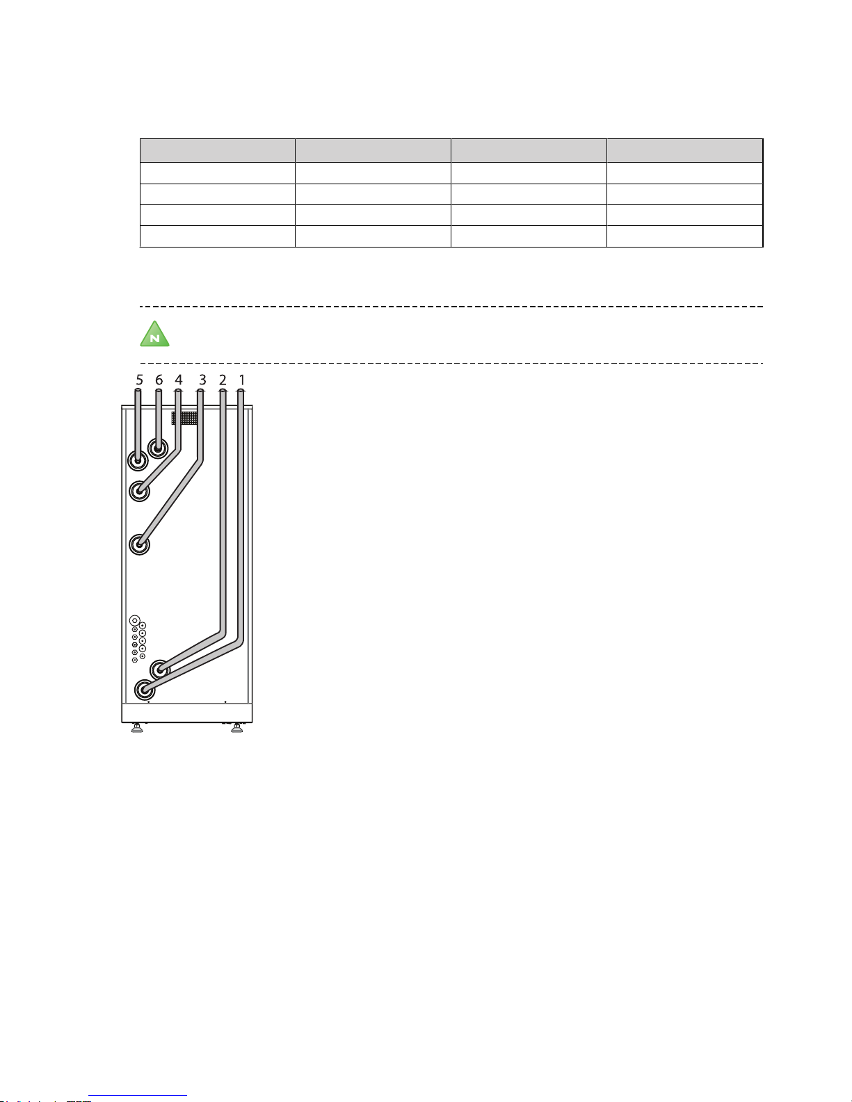
When installing in confined spaces, pipe routing on the rear of the heat pump can be facilitated by connecting the
pipes before the pump is put in position. The following figure shows an example of how the pipes can be routed.
Note! Remember not to tighten the pipes in the heat pump’s panel casing as this transfers vibrations causing
noise problems.
Symbol explanation
1 Coolant out (from the heat pump)
2 Heat return (return line)
3 Return line hot-gas exchanger
4 Supply line hot-gas exchanger
5 Heat supply (supply line)
6 Coolant in (to the heat pump)
3.3 Required service space
To facilitate the installation and subsequent testing and maintenance there must be sufficient free
10 – Installation instructions VMIFJ102
Page 13

space around the heat pump in accordance with the following dimensions:
300
50
500
300
600
Figure 9. Service space
3.4 Technical data
Table 3. Technical data
The rmia Heat Pum ps re serv es th e rig ht t o make chan ges w ithou t fur the r not ice. 13092 3_R_EN G
The meas urements are perf ormed on a limited n umber of heat pumps whic h
can cause v ariations in t he results. Toler ances in the measur ing methods ca n
also cause vari ations.
1) B0/W35, A ccording to EN14511 incl. circ.pump.
2) Nomina l flow heating ci rcuit ∆10K , cooling ci rcuit ∆3K.
3) Anti -freeze in cooling ci rcuit: Ethanol -water.
4) At nomin al flow.
5) Please n ote that not all co oling circuit t emperatures a nd heating
temper atures can be com bined.
6) Min. inc oming cooling c ircuit temper ature 0°C.
7)
Sound power level measured according to EN 12102 and EN ISO 3741 at B0W35
8) Always c heck local rules a nd regulations b efore using ant ifreeze.
DHP-S Eco 22 26 33 42
Refrigerant Type R410A R410A R410A R410A
Amount kg 3.8 3.9 4.5 4.6
Test pressure MPa 4.5 4.5 4.5 4.5
Design pressure MPa 4.3 4.3 4.3 4.3
Compressor Type Scroll Scroll Scroll Scroll
Oil POE POE POE POE
Electrical data
3-N
Main supply Volt 400 400 400 400
Rated power, compressor
Rated power, circulationpumps
kW
kW
9,91
0.5
12,40
0.5
14,83
0.6
19,12
0.6
Start current A 21.7 23.8 32.2 37.1
Fuse A 20 25 32 32
Performance COP
1
Heating capacity
1
Electrical power
1
kW
kW
4.40
21.9
5.0
4.40
25.4
5.8
4.37
33.5
7.7
4.31
41.4
9.6
Nominal flow
2
Cooling circuit
3
l/s 1.4 1.5 2.1 2.4
Heating circuit l/s 0.5 0.6 0.8 0.9
External available
pressure drop
4
Cooling circuit kPa 81 75 73 63
Heating circuit kPa 75 70 66 50
Internal pressure drop Condenser
Evaporator
kPa
kPa
2.3
23.8
6.6
27.0
5.0
33.0
16.0
37.0
Maximum system pressure Brine
Heat transfer fluid
bar
bar
6
6
6
6
6
6
6
6
Min/max temperature
5
Cooling circuit °C 20/-10 20/-10 20/-10 20/-10
Heating circuit
6
°C 65/20 65/20 65/20 65/20
Pressure switches Low pressure
Operating
MPa
MPa
0.35
4.0
0.35
4.0
0.35
4.0
0.35
4.0
High pressure MPa 4.3 4.3 4.3 4.3
Sound power level
7
dB (A) 55 55,2 56,4 56
Anti freeze media Ethanol+water solution -17°C ± 2
8
Weight kg 225 241 262 271
Page 14

R410A
T brine °C T water °C
20 65
0 65
-5 60
-10 54
-10 20
5 20
20 30
0
10
20
30
40
50
60
70
-15 -10 -5 0 5 10 15 20 25
Twater °C
Tbrine °C
Min/Max Operation Temperature R410A
Page 15

4 Drilling holes for brine pipes
Caution! Ensure that the holes for the insert pipes are positioned so that there is room for the other
installations.
Caution! The brine pipes shall have separate lead-ins. If the wall lead-ins are below the highest ground water
level watertight lead-ins must be used.
The brine pipes must be insulated from the heat pump, through the walls and outside the house all the way to the
collector so as to avoid condensation and prevent heat loss.
If the brine pipes are to be routed above ground, drill holes in the walls for them.
If the brine pipes are to be routed below ground see the instructions below.
1
1
2
3
3
4
Figure 10. Making holes
Symbol explanation
1 Insert pipe
2 Brine pipe
3 Mortar
4 Sealant
1. Drill holes in the wall for the insert pipes (1) for the brine pipes. Follow the dimension and connection diagrams.
If there is any risk of groundwater infiltration at brine pipe lead-ins, watertight grommets must be used.
2. Position the insert pipes (1) in the holes sloping downwards. The inclination must be at least 1cm every 30cm.
Cut them at an angle (as illustrated) so that rain water cannot get into the pipes.
3. Insert the brine pipes (2) into the insert pipes in the installation room.
4. Fill in the holes around the lines with mortar (3).
5. Ensure that the brine pipes (2) are centred in the insert pipes (1) so that the insulation is distributed equally
on all sides.
6. Seal the insert pipes (1) with a suitable sealant (foam) (4).
Installation instructions VMIFJ102 – 13
Page 16

5 Unpacking and installation
The heat pump is packed in boxes and wrapped in cardboard and delivered on a wood pallet.
1. Check that the delivery is complete and undamaged.
Caution! When moving the heat pump, do not use the protruding pipe connections to lift the heat pump.
The packaging should not be used to lift the heat pump either.
5.1 Setting up
1. Move the heat pump to the installation site.
2.
Cut off the straps and remove the packaging.
3. Lift the heat pump from the pallet.
4. Install a condensation drain if required.
1
Figure 11. Make sure that the heat pump is level
using a spirit level
Symbol explanation
1 Adjustable feet
5. Adjust using the adjustable legs (1) so that the heat pump stands upright and level on the floor.
5.2 Removing the front cover
Remove the front cover plate as follows:
1.
Unscrew the screws (1).
2. Slide the front cover (2) upwards and carefully lift it off upwards and forwards.
3. Place the front cover next to the heat pump.
14 – Installation instructions VMIFJ102
Page 17

2
1
Figure 12. Remove the front
cover
Symbol explanation
1 Screws
2 Front panel
Installation instructions VMIFJ102 – 15
Page 18

6 Piping installation
Caution! To prevent leaks ensure that there are no stresses in the connecting lines!
Note! Ensure that the pipe installation is carried out in accordance with the dimensions and connection
diagrams.
Note! Pipe installation must be carried out by an authorized installer.
Caution! It is important that the heating system is bled after installation.
Caution! Bleed valves must be installed where necessary.
6.1 Safety valve
Note! The heat pump must be connected to the expansion tank and the safety valve according to applicable
regulations. The connection between the reservoir and the safety valve must be routed in a continuous
incline. A continuous upwards slope means that the pipe must not slope downwards from the horizontal at
any point.
Caution! The brine circuit must be filled with the correct amount of fluid otherwise the installation may
become damaged. Ensure that system has the necessary pressure, however, not above maximum pressure
of 6 bar.
Caution! Heating systems with closed expansion tanks must also be supplied with approved pressure gauges
and safety valves.
6.2 Heating system supply pipe and return pipe
1. Install a filter (max mesh size 0.7 mm) in the heating system’s return pipe to protect the unit against foreign
particles.
2. Install the supply line with all the accompanying components.
3. Install the return line with all the accompanying components.
4. Insulate the supply and return lines.
16 – Installation instructions
VMIFJ102
Page 19

6.3 System suggestion
50
72
36
51
117
83
80
77
86
97
8684
111
80
92
1
90
34
91
53
55
82
81
19
115
112
84 83 82 31
82
83
88
19
75
Figure 13. System suggestion
Symbol explanation
1 Heat pump 82 Adjustment valve
19 Water heater 83 Non-return valve
31 Circulation pump (VVC) 84 Pressure gauge
34 Circulation pump, (hot gas) 86 Safety valve
36 Circulation pump (system) 88 Valve pipe (cold water)
50 Outdoor sensor 90 Dirt strainer (hp)
51 System supply line sensor 91 Dirt strainer (hot gas)
53 Hot water sensor start 92 Dirt strainer (heat transfer fluid)
55 Hot water sensor top (Installed in the heater that is hottest) 97 Flexible hose
75 Mixer valve 111 Venting and expansion tank (heat transfer fluid)
77 Reversing valve 112 Expansion vessel (closed)
80 Shut-off valve 115 Immersion heater
81 Filler valve 117 Auxiliary heat
A heat pump can produce both heat and hot water. With an external auxiliary heater (oil boiler, electric boiler, district
boiler or similar) heat production is supported but not hot water production. The exchange valve for heating and
hot water is located ahead of the external auxiliary heater, which allows the production of heating and hot water at
the same time. The heat pump control computer also controls an additional shunt located after the external addition.
The SERVICE menu selects AUX. HEATER, EXT.AUX.HEATER. Default setting is:
•
EXT.AUX.HEATER = ON
•
REV.V. HOT WATER = INT
When an oil boiler is used as addition, the after burning time is activated to 60 minutes.
The SERVICE menu selects AUX. HEATER, EXT.AUX.HEATER, TURN OFF DELAY, 60M
Installation instructions
VMIFJ102 – 17
Page 20

7 Electrical Installation
7.1 Electrical connection
Caution! Electrical installation may only be carried out by an authorized electrician and must follow
applicable local and national regulations.
Caution! The electrical installation must be carried out using permanently routed cables. It must be possible
to isolate the power supply using an all-pole circuit breaker with a minimum contact gap of 3 mm.
DANGER! The terminal blocks are live and can be highly dangerous due to the risk of electric shock. The
power supply must be isolated before electrical installation is started. The heat pump is internally connected
at the factory.
1. Remove the front cover from the heat pump.
2. Pull the power supply cable through the opening in the rear of the heat pump to the terminal blocks.
3. Connect the supply cable to the designated terminal blocks.
See separate manual for wiring diagram.
DANGER! Electrical current! The power cable may only be connected to the terminal block intended for this
purpose. No other terminal blocks may be used!
Electrical cabinet layout
K2
K1
F10
F11
X1
F0
F3
F4
1
E1
1
F1
Figure 14. Electrical cabinet
Symbol explanation
K1 Contactor compressor
K2 Contactor brine pump
F10 Over current relay compressor.
F11 Over current relay brine pump
F1 Fuse brine pump
F0 Control fuse regulation, overheating
protection compressor
F3 Control fuse heat addition
F4 Control fuse Oil and Electricity
X1 Terminal blocks for incoming supply
and temperature sensor as well as ter-
minal blocks for external components
1 Space for extra board
7.2 Connecting pump hot gas
1. Connect the hot gas pump to the designated terminal blocks. The voltage is 230 VAC. The pump is designed
to be placed outside the heat pump casing and must be connected with flexible hoses.
This pump runs in parallel with the compressor.
See separate manual wiring diagram.
18 – Installation instructions VMIFJ102
Page 21

7.3 Connecting sensor for outside temperature
Position the outdoor sensor on the north or north west facing side of the house, away from direct sunlight. The
outdoor sensor should not be placed on reflective panel walls. The sensor must be positioned at least 1 m from
openings in the walls that emit hot air.
If the sensor cable is connected through a pipe, the pipe must be sealed so that the sensor is not affected by outgoing
indoor air.
1. Route the outdoor sensor’s connecting cable through the opening in the rear of the heat pump up to the
connecting block.
2. Connect the sensor to the designated terminal block.
See separate manual for wiring diagram.
Caution! The outdoor sensor uses protected extra low voltage. Follow the specific installation instructions
for the outdoor sensor!
7.4 Connecting hot water sensor
Connect the hot water sensor to the designated terminal blocks. The sensor should be positioned a third way up
from the bottom in the water heater which is hottest.
See separate manual for wiring diagram.
7.5 Connecting sensor for system supply temperature
The system supply sensor must always be installed on the system’s supply pipe after the auxiliary heater. The sensor
must be positioned so that the heated water has been able to mix properly.
See separate manual for wiring diagram.
7.6 Connecting exchange valve for hot water
See separate manual for wiring diagram and exchange valve.
7.7 Connecting room sensor (option)
Remove the front cover from the heat pump.
1. Route the room sensor’s connecting cable through the opening in the rear piece up to the connecting block.
2.
Connect the sensor to the designated terminal block.
See separate manual for wiring diagram.
7.8 Connecting pressure and flow sensor (option)
See separate manuals for wiring diagram and pressure and flow sensor.
7.9 Connecting start and stop auxiliary heater
Connect start/stop of auxiliary heater to designated terminal block.
See separate manual for wiring diagram.
7.10 Connecting control signal for auxiliary heater
See separate manual for wiring diagram.
7.11 Conversion table for sensors
Caution! When reading the resistance of the sensors, the sensor leads must first be disconnected from the
control equipment.
Installation instructions VMIFJ102 – 19
Page 22

Table 4. Outdoor sensor
°C ohm, Ω
-30 1884
-25 1443
-20 1115
-15 868
-10 681
-5 538
0 428
5 343
10 276
15 224
20 183
25 150
30 124
35 103
40 86
Table 5. other sensors
°C kilo ohm, kΩ
0 66,3
5 52,4
10 41,8
15 33,5
20 27,1
25 22,0
30 18,0
35 14,8
40 12,2
45 10,1
50 8,5
55 7,1
60 6,0
65 5,0
70 4,2
75 3,7
80 3,1
85 2,7
7.11.1 Measurement checking sensors during fault tracing
1. Disconnect the relevant sensor from I/O-card/terminal block.
2. Measure the resistance for the sensor and any extension cables.
3. Then measure the sensor only.
Note! To ensure the sensor value the actual temperature must be checked against the measured resistance.
20 – Installation instructions VMIFJ102
Page 23

8 Test operation
Note! Read the safety instructions!
Caution! The installation may only be commissioned if the heating system, water heater and brine system
have been filled and bled. Otherwise the circulation pumps can be damaged.
Caution! Any alarms that may occur in connection with the installation must be fault-traced.
Caution! If the installation is only to provide heat by an auxiliary heater during the installation, ensure that
the heating system is filled and bled and the compressor cannot be started. This is carried out by setting the
operating mode to AUX. HEATER.
8.1 Installation checklist
Before manual test operation, the following points must be checked to ensure that they have been correctly carried
out:
•
Piping installation
•
Electrical Installation
8.1.1 Piping installation, heating system
•
Pipe connections in accordance with the connection diagram
•
Flexible hoses on the supply and return lines
•
Surge tank on supply line
•
Pipe insulation
•
Strainer on return line
•
Bleeding of the heating system
•
All radiator valves fully open
•
Expansion tank heating system (not included in the delivery)
•
Safety valve for expansion vessel (6 bar) (not included in the delivery)
•
Filler cock heating system (not included in the delivery)
•
Leakage inspection
If a an external water heater is installed, also check:
•
Reversing valve
•
Safety valve for cold water (9 bar)
8.1.2 Electrical Installation
•
Circuit-breaker
•
Fuse protection
•
Direction of rotation of the compressor
•
Coolant pump
•
Positioning of the outdoor sensor
Installation instructions VMIFJ102 – 21
Page 24

•
Control computer settings
If a an external water heater is installed, also check:
•
Reversing valve
8.1.3 Brine system
•
Expansion/bleed tank on the return pipe
•
Safety valve for expansion vessel (6 bar)
•
Filler cock on the return pipe
•
Insulation in the outside wall lead-in
•
Other brine pipe insulation
•
Bleeding of brine system
•
Leakage inspection
8.2 Manual test
Test operate and at the same time check the function of the components.
8.2.1 Activate MANUAL TEST
1. Ensure that the main circuit breaker is on.
2. Select operating mode
, in the menu INFORMATION -> OPERAT.->
3. Open the SERVICE menu by pressing and holding < in for five seconds.
4. Set the value for MANUAL TEST to 2.
Note! Set MANUAL TEST to 2 to navigate away from the menu during ongoing test operation.
8.2.2 Test the brine pump
1. Start the brine system’s brine pump by setting the value BRINE PUMP to 1.
2.
Check that the brine pump is running by:
•
listening
•
putting a hand on the pump
•
checking that the level in the expansion tank is stable. If the level is not stable there is air in the system.
•
listen for air
3. If the pump does not start automatically, perform manual start.
4. If there is air in the brine system, bleed the system.
5. Stop the brine pump by setting the value to 0.
8.2.3 Test the circulation pump
1. Start the heating system circulation pump by setting the value CIRC. PUMP to 1.
2.
Check that the circulation pump is running by carrying out the following:
•
Listen
•
Place a hand on the pump
•
Listen for air
3. If the pump does not start, see Starting circulation pumps manually
4. If there is air in the heating system, vent, see Bleeding the heating system
5. Stop the circulation pump by setting the value to 0.
22 – Installation instructions VMIFJ102
Page 25

8.2.4 Test the exchange valve (if hot water is in the installation)
1. Activate the 3-way valve by setting the value REV.V. HOT WATER to 1.
2.
Check that the arm on the 3-way valve changes position.
3.
If the arm does not change position, perform fault tracing.
8.2.5
Test the compressor
1.
Start the circulation pump by setting the value CIRC.PUMP to 1.
2. Start the heat pump compressor by setting the value HEAT PUMP to 1. At the same time as the value is set to
1 for HEAT PUMP the brine pump starts.
Warning! Risk of burn injury, the pressure pipe on the compressor can get up to 70-80 degrees in temperature
after operating for a while!
Installation instructions VMIFJ102 – 23
Page 26

1
Figure 16. The
pressure pipe should
get hot during operation
Symbol explanation
1 Note! Hot!
1.
Check that:
•
the compressor is running in the right direction by putting a hand on the pressure pipe before the compressor starts, the pipe is then cold. Feel again after a short while to ensure the pressure pipe becomes
properly hot.
•
it sounds normal and there is no noise.
2.
If the pipe does not get hot, or if the compressor sounds abnormal, perform fault tracing.
3.
Stop the compressor by setting the value to 0.
4.
Stop the brine pump by setting the value to 0.
5.
Stop the circulation pump by setting the value to 0.
8.2.6
Testing the auxiliary heating power stages
1.
Start the circulation pump by setting the value CIRC. PUMP to 1
AUX. HEAT 1
1.
Start the first auxiliary heating power stage by setting the value ADD.HEAT 1 to 1.
2. Check that the auxiliary heater step works by exiting the MANUAL TEST menu and entering the INFORMATION
-> TEMPERATURE -> SUPPLY LINE menu and check that the temperature rises.
3.
Return to the menu MANUAL TEST and stop AUX. HEAT 1 by setting the value back to 0.
AUX. HEAT 2, AUX. HEAT 3
1.
Repeat the steps in AUX. HEAT 1 for AUX. HEAT 2 and AUX. HEAT 3.
2.
Stop the circulation pump by setting the value to 0.
8.2.7 Test fuse protection
1. Start the circulation pump by setting the value CIRC. PUMP to 1
2.
Start the compressor by setting the value HEAT PUMP to 1.
3. At the same time, start the auxiliary heating power stages available to check that the fuse protection can
withstand full power operation.
4. Stop the auxiliary heating power stages and the compressor by setting the value back to 0.
5. Stop the circulation pump by setting the value to 0.
8.2.8
Exit test operation
Set the value for MANUAL TEST to 0.
24 – Installation instructions VMIFJ102
Page 27

9 Start up
9.1 Adaptation to the heating system
Adjust the heat pump settings to the applicable heating system, for instance an underfloor heating or radiator system.
The delta temperature must be at least 8°C above the heat pump. The delta temperature should be 3–5°C for the
brine system. If none of the delta temperatures are reached, the flow of the circulation pumps may need adjusting
depending on the applicable heating system.
9.1.1 Noise check
During transportation and installation there is a certain risk that the heat pump can be damaged, components may
move or get bent and this can cause noise. Because of this it is important to check the heat pump when it has been
installed and is ready to be commissioned to ensure that everything is in order. The heat pump should be tested in
both heating and hot water modes to ensure that there is no abnormal noise. While doing this, check that there is
no abnormal noise in other parts of the house.
9.1.2 Select operating mode
Set the heat pump to the desired operating mode in the menu INFORMATION -> OPERAT. If necessary, set certain
parameters in the control system, such as ROOM and CURVE.
Installation instructions VMIFJ102 – 25
Page 28

10 Installing the front cover
2
1
Figure 17. Assembling the
front cover
Symbol explanation
1 Screws
2 Front panel
Caution! Take care not to damage the front cover or display cables!
Install the front cover as follows:
1. Align the upper section of the front cover (2) in both the side channels on the unit and slide it carefully
downwards until it covers the entire front side.
2. Tighten the front plate (2) with the screws (1).
26 – Installation instructions
VMIFJ102
Page 29

11 Menu information
Menu description regards software with version 1.3.
The heat pump has an integrated control system which automatically calculates the heat demand in the house to
ensure that the correct amount of heat is produced and emitted where necessary. There are many different values
(parameters), which are required in order to do the calculation of the heat demand.
During installation and service, the control panel is used to set and change values that have to be adapted according
to the house demand. The control panel consists of a display, a keypad and an indicator. In the display, a simple menu
system is used to navigate the desired settings and values. During operation, the display always shows the set ROOM
value, the operating mode and the status of the heat pump.
3
2
1
ROOM
NO HEAT DEMAND
OPERAT. AUTO
20°C
Figure 18. Display, keypad and indicator.
Position Description
1 The display text and symbols are only shown as examples. Certain symbols cannot be displayed at the
same time.
2 Keypad:
+ Plus sign used to scroll up a menu or increase the values.
- Minus sign used to scroll down a menu or reduce the values.
> Right arrow used to select a value or open a menu.
< Left arrow to cancel selection or exit a menu.
3 Indicator
The control system is operated via a user-friendly menu system, which is shown in the display. Use the keypad’s four
navigation symbols to navigate the menus and increase or reduce the set values.
The control system is divided into the following two main menus:
•
INFORMATION
•
SERVICE
The INFORMATION menu is used to adjust the following (also see INFORMATION menu:
•
Operation
•
Heat curves
•
Temperatures
•
Operating time
•
Menu system language
Installation instructions
VMIFJ102 – 27
Page 30

The SERVICE menu is used during installation and services with many settings, see Installation instructions.
1
2
Figure 19. The menus are reached by pressing different buttons.
Position Description
1 Information menu
Press the left or right buttons.
2 Service menu
Press and hold the left button for at least five seconds
The INFORMATION menu is opened by pressing the left or right buttons.
For installation and service, the SERVICE menu is used, which is opened by pressing the left button for five seconds.
The indicator at the bottom of the control panel has three modes:
•
Not lit, means that the heat pump is not powered.
•
When the light shines continuously, the heat pump has power and is ready to produce heat or hot water.
•
Flashing, means an active alarm
Caution! During a service that consists of replacing the display card, all heat pump settings are reset to factory
settings. Therefore note current settings before replacement.
11.1 SERVICE menu
The SERVICE menu is for use during installation and service to optimise and adjust the operation of the heat pump.
Open the menu by pressing the left button for five seconds. Menus in italics are visible if the expansion card is installed.
Table 6.
Used to change the heat pump's default settings.
Menu Sub menu Sub menu Sub menu
SERVICE
HOT WATER
START
HOT WATER TIME
HEATING TIME
TOPH. INTERVAL
TOPH. TIME
TOPH. STOP
INFL. H.W SENSOR
WEIGHT HOT WATER
HEAT PUMP
28 – Installation instructions VMIFJ102
Page 31

Menu Sub menu Sub menu Sub menu
INTEGRAL A1
HYSTERESIS
MAX RETURN
START INTERVAL
ALARM BRINE
PRESS. PIPE
OUTDOOR STOP
SHUNT TIME
SHUNT COOLING
AUX. HEATER
MAX STEP
INTEGRAL A2
HYSTERESIS
MAX CURRENT
HOT WATER STOP
DELAY AFTER EVU
EXT.AUX.HEATER
EXT.AUX.HEATER
INTEGRAL A3
TURN OFF DELAY
REV.V. HOT WATER
TOPH. EXT
MANUAL TEST
MANUAL TEST
HEAT PUMP
CIRC. PUMP
REV.V. HOT WATER
SHUNT
SYSTEM SHUNT
HGW-SHUNT
AUX. HEAT 1
AUX. HEAT 2
AUX. HEAT 3
EXT.AUX.HEATER
EXT. CIRC. PUMP
ALARM
SHUNT COOLING
SHUNT GROUP
2ND H.C SHUNT
PASSIVE COOLING
COOLING A
REV. V. POOL (Expansion
card)
0-10V
Table 7. Used to change the heat pump's default settings. (continued)
Menu Sub menu Sub menu Sub menu Sub menu
SERVICE
INSTALLATION
SYSTEM
HEAT SOURCE
GROUND OR ROCK
OUTSIDE AIR
BRINE SOLUTION
DIRECT EVAP.
COOLING
Installation instructions VMIFJ102 – 29
Page 32

Menu Sub menu Sub menu Sub menu Sub menu
PASSIVE COOLING
ACT COOLING
POOL (Expansion card)
SHUNT GROUP
BUFFER TANK
BUFFER TANK
NO. OF CIRCUITS
SYSTEM SHUNT
2ND H.C SHUNT
ADDITION
0-10V
Ø
EXT. AUX. HEATER
CURRENT LIMITER
SERVICE TIME
FACTORY SET
CANCEL
RADIATOR
FLOOR
RESET OPER. TIME
SENSOR CALIBRATION
OUTDOOR
SUPPLY LINE
RETURN LINE
HOT WATER
REFR 1
REFR 2
REFR 3
POOL
SHUNT GROUP
HGW TEMPERATURE
BUFFER TANK
2ND HEAT CIR.
SYSTEM SUPPLY
EXTERNAL FACTOR
VERSION
DISPLAY
I/O-CARD
LOG TIME
DEFROST
DEFR CURVE 0
DEFR CURVE -XX
STOP DEFR
BELOW 5°C DEFR
MIN TIME DEFR
MAX RAD STMP
FAN START
FAN STOP
REFR 3
30 – Installation instructions VMIFJ102
Page 33

11.1.1 Sub menu HOT WATER
Table 8. Used to change the settings for hot water production.
Menu selection Meaning Factory setting
START
Start temperature for hot water production. Shows the actual weighted hot water temperature and the value within brackets indicates
the start temperature. ( = no sensor alarm)
(range: , 30°C / 55°C)
HOT WATER TIME
Time for hot water production during combined hot water and heating demand, in minutes.
20M
(range: 5M / 40M)
TOPH. TIME
Time in hours that the legionella demand is to be fulfilled for legionella operation to be considered complete.
0M
(range: 1M / 10M
HEATING TIME
Time for hot water production during combined heating and hot
water demand, in minutes.
20M
(range: 5M / 40M)
TOPH. INTERVAL
Time interval between peak heating chargings (anti-legionella function) in days. Operating mode that permits auxiliary heater must be
selected.
7D
(range:
, 1D / 90D)
TOPH. STOP
Stop temperature for peak heat charging. Operating mode that permits auxiliary heater must be selected.
60°C
(range: 50°C / 65°C)
INFL. H.W SENSOR.
Water heater sensor’s influence compared with the peak sensor’s at
start of water heating.
65%
(range: 0% / 100%)
WEIGHT HOT WATER
The calculated value of the hot water sensor directed towards the
peak sensor.
-
11.1.2 Sub menu HEAT PUMP
Table 9. Used to change the heat pump's operating settings.
Menu selection Meaning Factory setting
INTEGRAL A1
The integral’s value for starting the heat pump. See Important
parameters for more information.
-60°min
(range: -250°in / -5°in)
HYSTERESIS
If the difference between the actual supply temperature and the
calculated supply temperature is too great either the integral
value is set to start value A1 (the heat pump starts) or the value is
set to 0 (stops the heat pump).
12°C
(range: 1°C / 15°C)
MAX RETURN
Stop temperature at high return from the heating system. 55°C
(range: 30°C / 70°C)
START INTERVAL
Minimum time interval between two heat pump starts in minutes. 20M
(range: 10M / 30M)
ALARM BRINE
Gives an alarm when the outgoing brine temperature falls below
the set value.
(range: , -14°C / 10°C)
PRESS. PIPE
Sensor on the compressor’s hot gas line. Value within brackets
indicates maximum permitted temperature. If this value is exceeded, the compressor will stop and start again as soon as the temperature has dropped. No alarm shown in the display, however, a
square is shown in the left, lower corner of the display.
140°C
SHUNT TIME
Time in seconds. Indicates how often the shunt is to adjust its
opening.
60S
(range: 10S / 99S
SHUNT COOLING
The cooling shunt works towards the set temperature. 18°C
(range: 0°C / 30°C)
Installation instructions VMIFJ102 – 31
Page 34

11.1.3 Sub menu AUX. HEATER
Table 10. Used to change the heat pump stages’ operating settings.
Menu selection Meaning Factory setting
MAX STEP
Maximum number of permitted steps for auxiliary heating.
= no auxiliary heating permitted (Means that only AUTO,
HEAT PUMP or [SYMBOL] can be selected and that no antilegionella operation is possible.)
(range: , 1
INTEGRAL A2
Two conditions must be fulfilled in order to start the auxiliary
heater: the integral’s value to start must be less than integral
A1 + A2, and the supply temperature must be 2°C lower than
the calculated temperature. See Important parameters for further information.
-600
(range: -50 / -990)
HYSTERESIS
If the difference between the actual supply temperature and
the calculated supply temperature is too great (see Important
parameters), either the integral value is set to start value A1 +
A2 (starts the auxiliary heater) or to 0 (stops the auxiliary
heater ).
20°C
(range: 5°C / 30°C)
DELAY AFTER EVU
Time in minutes. Indicates how many minutes after EVU are to
pass before the auxiliary heater may be activated.
30M
(range: 0M / 120M
Max Current
(Expansion card)
Refers to main fuse in the unit, in amperes 20
(range: 16 / 35)
HOT WATER STOP
Stop temperature for hot water during AUX. HEATER. The value
is read off by the hot water sensor.
60°C
(range: 50°C / 65°C)
EXT.AUX.HEATER
Menu selection Meaning
EXT.AUX.HEATER
Switch the
external auxiliary heater off
and on.
OFF / ON
INTEGRAL A3
Indicates the
value of the
integral when
external auxiliary heater is
connected.
-300
(range: -990 / INTEGRAL
A1 - 10)
TURN OFF DELAY
Indicates how
long the
external auxiliary heater
must continue to be
active after its
demand is no
longer needed.
0M
(range: 0M / 180M)
32 – Installation instructions VMIFJ102
Page 35

Menu selection Meaning Factory setting
REV.V. HOT WATER
Indicates
whether the
exchange
valve for hot
water is located before or
after the
external auxiliary heater.
(Determines
whether the
external auxiliary heater
may produce
hot water.)
INT / EXT
TOPH. AUX
Indicates
whether the
external auxiliary heater
can be used
for antilegionella.
OFF / ON
11.1.4 Sub menu MANUAL TEST
Table 11. Used to manually test and test operate the heat pump’s components or signal outputs.
Menu selection Meaning Factory setting
MANUAL TEST
0 = deactivate manual test
1 = activate manual test
2 = activate manual test with option of navigating from the SERVICE menu to
check that the temperatures rise for example.
-
HEAT PUMP
0 = stop heat pump
1 = start heat pump
Note! The heat pump cannot be started in the event of an
active alarm.
-
BRINE PUMP
0 = stop the brine pump
1 = start the brine pump
-
CIRC. PUMP
0 = stop the circulation pump
1 = start the circulation pump
-
REV.V. HOT WATER
0 = heating mode for the exchange valve
1 = hot water mode for the exchange valve
-
SHUNT
- = closes shunt
0 = shunt unaffected
+ = opens shunt
SYSTEM SHUNT
- = closes shunt
0 = shunt unaffected
+ = opens shunt
Only at buffer tank
HGW-SHUNT
- = closes shunt
0 = shunt unaffected
+ = opens shunt
AUX. HEAT 1
0 = stop aux. heater step 1
1 = start aux. heater step 1
-
AUX. HEAT 2
0 = stop aux. heater step 2
1 = start aux. heater step 2
Installation instructions VMIFJ102 – 33
Page 36

Menu selection Meaning Factory setting
AUX. HEAT 3
0 = stop aux. heater step 3
1 = start aux. heater step 3
EXT.AUX.HEATER
0 = stop external auxiliary heater
1 = start external auxiliary heater
EXT.CIRC. PUMP
0 = stop circulation pump
1 = start circulation pump
SHUNT DEFR
- = opens flow from defrosting tank
0 = shunt unaffected
+ = closes flow from defrosting tank
FAN L
0 = stop fan
1 = start fan at low speed
FAN H
0 = stop fan
1 = start fan at high speed
EXT. AUX. HEATER
0 = 0V on plinth 283
1 = control voltage 230V on plinth 283
ALARM
0 = stop signal on output External alarm
1 = start signal on output External alarm
-
SHUNT COOLING
- = closes shunt
0 = shunt unaffected
+ = opens shunt
-
SHUNT GROUP
- = closes shunt
0 = shunt unaffected
+ = opens shunt
2ND H.C SHUNT
- = closes shunt
0 = shunt unaffected
+ = opens shunt
Only at buffer tank
PASSIVE COOLING
0= stop passive cooling
1= start passive cooling
COOLING A
0= stop active cooling
1= start active cooling
REV. V. POOL
0 = normal mode for the exchange valve
1 = pool mode for the exchange valve
-
0-10V
Used for circulation pumps at BUFFER TANK. -
34 – Installation instructions VMIFJ102
Page 37

11.1.5 Sub menu INSTALLATION
Table 12. Used for settings that are set during installation.
Menu selection
Meaning Factory setting
SYSTEM
Sub menu SERVICE -> INSTALLATION -> SYSTEM:
Note! The menu selection in the SYSTEM menu varies depending on the selected values.
Tip: start in the top menu and work downwards.
Menu selection Meaning
HEAT SOURCE
Menu selection Meaning
DIRECT EVAP. The actual system with direct evaporation and four-
way valve.
POOL (Expansion
card)
ON /
Does not appear if SHUNT GROUP is selected.
SHUNT GROUP
ON /
When ON, HEAT CURVE 2 is activated in the INFORMATION menu. Not displayed if
POOL is selected.
BUFFER TANK (See
separate instruction
for buffer tank)
BUFFER TANK
NO. OF CIRCUITS
SYSTEM SHUNT
2ND H.C SHUNT
ADDITION
0-10V:
(Expansion card)
CURRENT LIMITER: ON / (Expansion card)
SERVICE TIME
Note! Only used for test operation. The heat pump counts 60 times
as fast, which means that the waiting times are eliminated during
test operation.
0 = deactivates SERVICE TIME
1 = activates SERVICE TIME, which speeds up the control system’s integral calculation and start delay by 60 times.
-
FACTORY SET
CANCEL = starting point, no changes made.
RADIATOR = reset factory settings for radiator system
FLOOR = reset factory settings for under floor heating
-
RESET OPER.
TIME
0 = no reset of operating times
1 = reset of operating times to zero
-
Installation instructions VMIFJ102 – 35
Page 38

Menu selection
Meaning Factory setting
SENSOR CALIBRATION
Following sensors can be found in the installation:
OUTDOOR
SUPPLY LINE
RETURN LINE
HOT WATER
REFR 1
REFR 2
REFR 3
POOL
SHUNT GROUP
BUFFER TANK
2ND HEAT CIR.
SYSTEM SUPPLY
DEFR SENSOR
EXTERNAL FACTOR Affects sensors that are installed inside the heat pump.
0 (range: -5°C / 5°C)
0 (range: -5°C / 5°C)
0 (range: -5°C / 5°C)
0 (range: -5°C / 5°C)
0 (range: -5°C / 5°C)
0 (range: -5°C / 5°C)
-5°C (range: -5°C / 5°C)
0 (At AIR 5) (range: 0 /
20)
VERSION
Shows the software version which is stored on the display card respectively the I/
O-card.
DISPLAY: V X.X
I/O-CARD: V X.X
-
LOG TIME
Time interval between collection points of temperature history in minutes. The history graphs always show the 60 last collection points, which means that the graphs
can display history from 1 hour up to 60 hours ago.
(The function is not active if there is an active alarm).
1M (range: 1M / 60M)
11.2 Important parameters
11.2.1 Heat production - calculating
The indoor temperature is adjusted by changing the heat pump’s heat curve, which is the control system’s tool for
calculating what the supply temperature should be for water that is sent out in the heating system. The heat curve
calculates the supply temperature depending on the outdoor temperature. The lower the outdoor temperature, the
higher the supply temperature. In other words, the supply temperature of the water fed to the heating system will
increase linearly as the outdoor air temperature falls.
The heat curve will be adjusted in connection with installation. It must be adapted later on, however, to obtain a
pleasant indoor temperature in any weather conditions. A correctly set heat curve reduces maintenance and saves
energy.
36 – Installation instructions VMIFJ102
Page 39

11.2.2 CURVE
The control computer shows the value for CURVE by means of a graph in the display. The heat curve can be changed
by adjusting the CURVE value. The CURVE value indicates the supply temperature of the water that is wanted to the
heating system at an outdoor temperature of 0°C.
4
2 0 0 - 2 0
2 4
4 0
5 6
2
3
1
5
Figure 20. Graph showing the set value 40 for CURVE.
Position Description
1 Temperature (°C)
2 Maximum setpoint value
3 Outdoor temperature (°C)
4 0°C
5 Set value (standard 40°C).
In the event of outdoor temperatures below 0°C, a higher setpoint value is calculated and in the event of outdoor
temperatures greater than 0°C, a lower setpoint value is calculated.
2 0 0 - 2 0
2 4
4 0
5 6
2
3
1
Figure 21. Increasing or reducing the CURVE changes the slope of the curve.
Position Description
1 Temperature (°C)
2 Maximum setpoint value
3 Outdoor temperature (°C)
If the CURVE value is increased, the heat curve will become steeper and if the value is reduced, it will become flatter.
The most energy efficient and cost effective setting is achieved by changing the CURVE value which leads to fewer
starts and longer operating times. For a temporary increase or reduction, adjust the ROOM value instead.
Installation instructions VMIFJ102 – 37
Page 40

11.2.3 ROOM
If you wish to increase or reduce the indoor temperature, change the ROOM value. The difference between changing
the ROOM value and the CURVE value is as follows:
•
When changing the ROOM value, the angle of the curve on the system's heat curve does not change, instead the
entire heat curve is moved by 3°C for every degree change of the ROOM value. The reason that the curve is
adjusted 3°C is that an approximate 3°C increase in supply temperature is usually needed to increase the indoor
temperature 1°C.
•
When changing the CURVE value, the angle of the curve on the system's heat curve changes.
2 0 0 -2 0
2 4
4 0
5 6
2
3
1
Figure 22. Changing the ROOM value changes the heat curve upwards or downwards.
Position Description
1 Supply temperature (°C)
2 Maximum supply temperature
3 Outdoor temperature (°C)
The relationship of the supply temperature to the outdoor temperature will not be affected. The supply temperature
will be increased or reduced by the same number of degrees all along the heat curve. I.E. The entire heat curve rises
or drops instead of the curve gradient changing.
This method of adjusting the indoor temperatures can be used for a temporary raise or drop. For long term increases
or reductions of the indoor temperature, the heat curve should be adjusted.
11.2.4 HEAT STOP
The HEAT STOP function automatically stops all production of radiator heat when the outdoor temperature is equal
to, or higher than, the value entered for heat stop.
When the heat stop function is activated, the circulation pump will be turned off - except when hot water is being
produced. The circulation pump will be "exercised" for one minute per day. The factory set value for activating heat
stop is an outdoor temperature of 17°C. If the heat stop function is active, the outdoor temperature must drop 3°C
when setting, before the heat stop is de-activated.
11.2.5 MIN and MAX
The MIN and MAX values are the lowest, respectively highest set point values that are allowed for the supply temperature.
Adjusting the minimum and maximum supply temperatures is particularly important if your home has under floor
heating.
If your house has under floor heating and parquet floors, the supply line temperature must not exceed 45°C. Otherwise
the floor might get damaged. If you have under floor heating and stone tiles, the MIN value should be 22-25°C, even
in summer when no heating is required. This is to achieve a comfortable floor temperature.
If your house has a basement, the MIN value should be adjusted to a suitable temperature for the basement in summer.
A condition for maintaining the heat in the basement in the summer is that all radiators have thermostat valves that
switch off the heat in the rest of the house. It is extremely important that the heating system and the radiator valves
are trimmed correctly. As it is usually the end customers themselves who have to carry out trimming, remember to
inform them how to carry it out correctly. Also remember that the value for HEAT STOP needs adjusting upwards for
summer heating.
38 – Installation instructions VMIFJ102
Page 41

11.2.6 TEMPERATURES
The heat pump can display a graph showing the history of the various sensors’ temperatures and you can see how
they have changed over 60 measurement points in time. The time interval between the measurement points can be
adjusted between one minute and one hour, factory setting is one minute.
History is available for all sensors, but only the set value is shown in the display for the room sensor. The integral
value that may appear is the heating system’s energy balance.
11.2.7 INTEGRAL
The heat demand in the house depends on the season and weather conditions and is not constant. The heat demand
can be expressed as temperature difference over time and can be calculated giving an integral value as a result (heat
demand). To calculate the integral value, the control system uses several parameters.
A heat deficit is needed to start the heat pump, and there are two integral values, A1 (default value = -60), which
starts the compressor and A2, (factory set = -600), which starts the auxiliary heater and A3, which starts the external
auxiliary heater. During heat production, the deficit reduces and when the heat pump stops, the inertia in the system
causes a surplus of heat.
The integral value is a measurement of the area under the time axis and is expressed in degree minutes. The figure
below shows the factory settings for the integral values that the heat pump has. When the integral value has reached
the set value for INTEGRAL A1 the compressor starts. If the integral value does not reduce but continues to increase
the internal additional heat will start when the integral value reaches the set value for A2 and the external value at
set value for A3
1 5
7
3
4
1 4
11
1 3
1 2
3
4
6
1 2
11
88
2
5
2
1 0
9
1
5
1 0
9
15
15
16
Figure 23. Starting and stopping heat pump operation based on integral values
Symbol explanation
1 Integral
2 Heat surplus
3 INTEGRAL A1
4 INTEGRAL A2
5 Heating deficit
6 Time
7 Heat pump operation
8 No operation
9 Compressor
10 Internal additional heater
Installation instructions VMIFJ102 – 39
Page 42

Symbol explanation
11 Compressor start (A1)
12 Auxiliary heater start A2
13 Aux. heater stop (latest by A1)
14 Compressor stop (=0)
15 INTEGRAL A3
16 External auxiliary heater
The calculation of the integral value stops during heat stop. The calculation of the integral value stops when heat
stop has stopped.
In this example INTEGRAL A3 < INTEGRAL A2. This means that the external addition will be activated earlier than the
internal addition. On the condition that these are activated.
11.2.8 HYSTERESIS
In order to start the heat in advance during sudden changes of the heat demand, there is a value, HYSTERESIS, which
controls the difference between the actual supply temperature, t1 and the calculated supply temperature, t2. If the
difference is equal to or greater than the set HYSTERESIS value (x), i.e. there is a heat demand, or the heat demand
disappears, quicker than the usual integral calculation, the integral value is forced to either the start value (-60)
INTEGRAL A1 or to the stop value (0).
1
5
2
8
9
3
4
6
7
Figure 24. Conditions for HYSTERESIS to force the integral value to change.
Position Description
1 Integral
2 Supply temperature
3 t
1
4 t
2
5 Time
6 Compressor stop (0)
7 Compressor start (-60)
8 Hysteresis (Δt) ≥ x
9 Hysteresis (Δt) ≥ x
40 – Installation instructions VMIFJ102
Page 43

12 References
Piping installation
Date ........................................................
Company ........................................................
Name ........................................................
Tel. No. ........................................................
Electrical Installation
Date ........................................................
Company ........................................................
Name ........................................................
Tel. No. ........................................................
System adjustment
Date ........................................................
Company ........................................................
Name ........................................................
Tel. No. ........................................................
Installation instructions
VMIFJ102 – 41
Page 44

VMIFJ102
Danfoss Heat Pumps
Box 950
671 29 ARVIKA
Phone +46 570 81300
E-mail: dhpinfo@danfoss.com
Internet: www.heating.danfoss.com
Danfoss can accept no responsibility for possible errors in catalogues, brochures and other printed material. Danfoss reserves the right to alter its products without notice. This also applies to products
already on order provided that such alterations can be made without subsequential changes being necessary in specifications already agreed. All trademarks in this material are property of the respective
companies. Danfoss Heating Solutions and the Danfoss Heating Solutions logotype are trademarks of Danfoss A/S. All rights reserved.
 Loading...