

Page 1
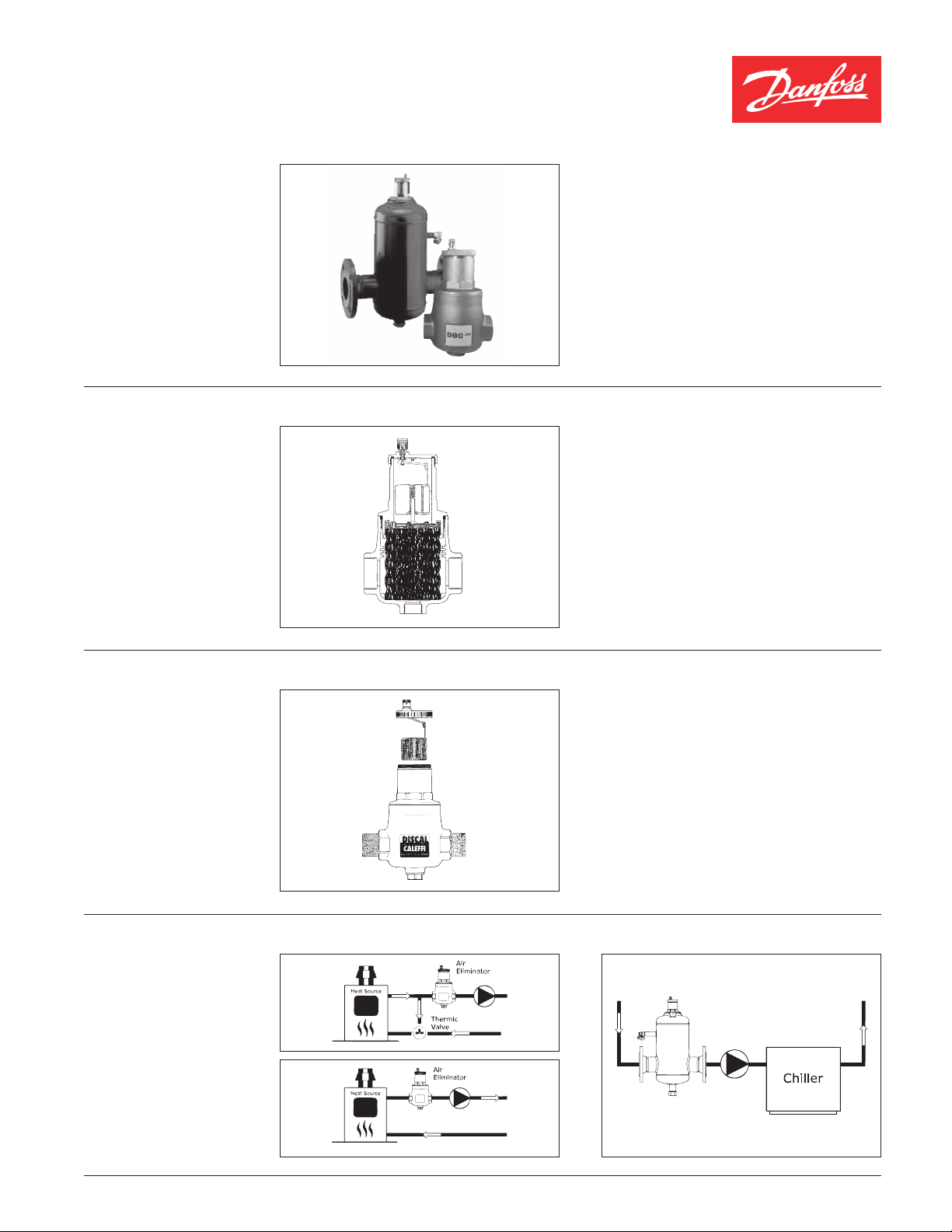
Data sheet DBC
Air Eliminators
For Heating and Cooling Systems
Features:
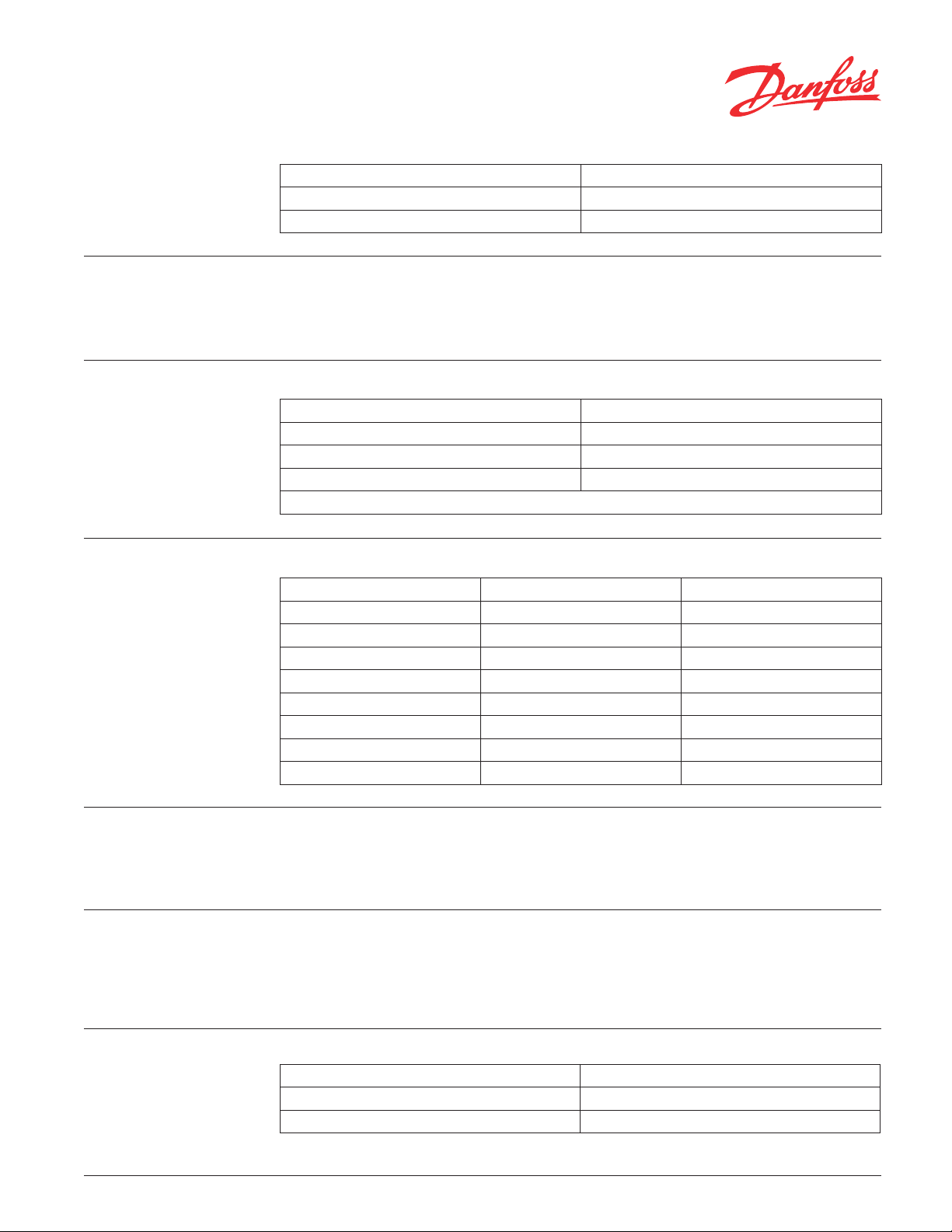
Performance Principal /
Induced Turbulence:
DBC air eliminators allow hydronic heating and
cooling systems to operate at their maximum
performance by quickly removing dissolved gas
particles and microscopic air bubbles from the
system. This translates to reduced corrosion,
higher system efficiencies, quicker start-ups and
decreased maintenance call backs.
As system fluid enters the air separating
chamber containing a metal lattice matrix,
the flow of the fluid becomes turbulent. The
turbulent flow causes variations in velocity and
pressure resulting in the accumulation of microair bubbles on the surface of the lattice.
As the bubbles merge, the buoyancy force
on the bubbles cause them to float to the
upper chamber of the air eliminator where it is
regulated and released by a float mechanism.
Vent Chamber:
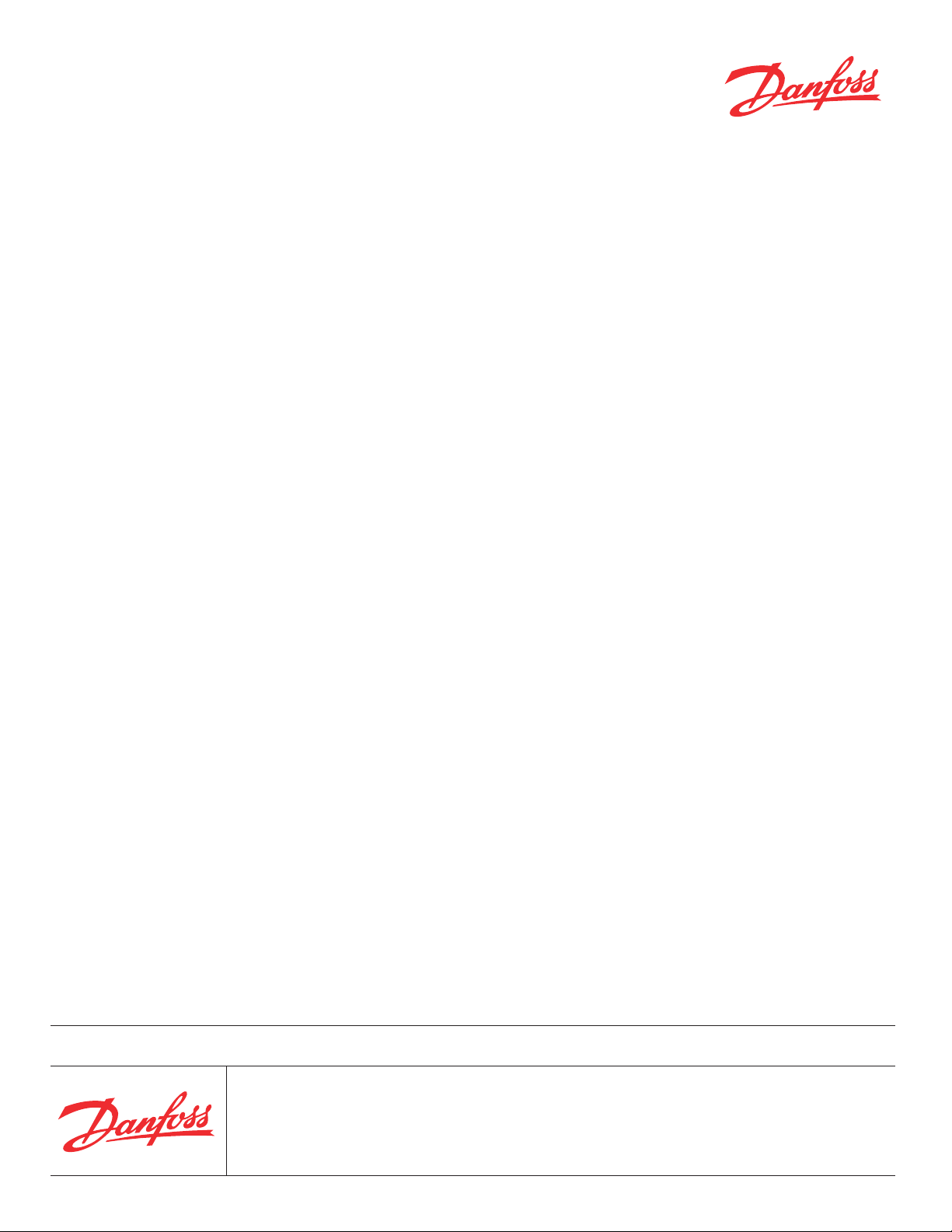
Installation Examples:
The float mechanism maintains a proper
air chamber at the top of the unit allowing
maximum performance of the vent valve.
VDFMA122 © Danfoss 05/09
1
Page 2
Data sheet
DBC
Air Eliminators
For Heating and Cooling Systems
System Connections:
Servicing:
Service Connections:
Ordering Information:
Size Connection
3/4” to 2” FNPT
2-1/2” to 4” ANSI Flange
The construction of DBC air eliminator allows
maintenance and cleaning without removal of
eliminator from the system. Brass models allow
Feature Size
Drain Plug (Models 3/4” - 2”) 1/2”
Drain Plug (Models 2-1/2” - 4) 1”
Purge Connection (Models 2-1/2” - 4”) 3/8”
Removable Vent (All Models)
Code Size Connections
551045DNF 3/4” NPT
551046DNF 1” NPT
551047DNF 1-1/4” NPT
551048DNF 1-1/2” NPT
551049DNF 2” NPT
551060DNF 2-1/2” ANSI Flange
551080DNF 3” ANSI Flange
551100DNF 4” ANSI Flange
for complete access to working internals. Steel
units allow access to vent assembly and blow
down valve for internal flushing.
Installation:
Preferred Location of
Separator:
Air Separator:
2
Orientation
DBC air eliminators are designed to be installed
with the float chamber in the vertical position.
Heating
Upstream of the circulator (Suction Side), downstream of the boiler. (ie: highest temperature,
lowest pressure)
Lattice Matrix Material Stainless Steel - All Models
Removable Lattice Brass Models Only
Rapid Manual Venting Ball valve on 2-1/2” to 4” models
VDFMA122 © Danfoss 05/09
Cooling
Upstream of the circulator (Suction Side) and
chiller (Return Side). (ie: highest temperature,
lowest pressure)
Page 3

Data sheet
DBC
Air Eliminators
For Heating and Cooling Systems
Materials of Construction:
Dimensions:
A
3/4” to 2”
2-1/2” to 4”
C
1/2”
B
Brass Body
EDPM Seals
NPT Connections
Stainless Steel Lattice Matrix
Steel, Enameled Painted
EDPM Seals
ANSI Flanges
Stainless Steel Lattice Matrix
F
C
D
E
A
Figure 1 Figure 2
B
D
E
Figure 1
Code No. A
551045D NF 3/4” 110.0 (4.3) 55.0 (2.2) 146.0 (5.7) 191.0 (7.5) N/A 1.7 (3.7)
551046 DNF 1” 110.0 (4.3) 55.0 (2.2) 146.0 (5.7) 191.0 (7.5) N/A 1.7 (3.7)
551047DNF 1-1/4” 124.0 (4.9) 55.0 (2.2) 166.0 (6.5) 211.0 (8.3) N/A 2.2 (4.9)
551048 DNF 1-1/2” 124.0 (4.9) 55.0 (2.2) 166.0 (6.5) 211.0 (8.3) N/A 2.2 (4.9)
551049DN F 2” NPT 127.0 (5.0) 55.0 (2.2) 160.0 (6.3) 211.0 (8.3) N/A 2.5 (5.5)
Figure 2
Code No. A
551060 DNF 2-1/2” ANSI 350.0 (13.8) 55.0 (2.2) 373.5 (14.7) 506.0 (20.0) 168.5 (6.6) 15.6 (34.4)
55108 0DN F 3” ANSI 466.0 (18.4) 55.0 (2.2) 435.5 (17.2) 595.0 (23.5) 219.0 (8.6) 28.0 (61.7)
551100DN F 4” ANSI 470.0 (18.5) 55.0 (2.2) 435.5 (17.2) 595.0 (23.5) 219.0 (8.6) 30.0 (66.1)
Flow Characteristics:
Connections 3/4” 1” 1-1/ 4” 1 -1/2 ” 2” NPT 2-1/2” ANSI 3” ANSI 4” ANSI
L/min 22.7 35.2 57.9 90.4 141.2 238.7 361.5 564.8
Gal/min 6.0 9.3 15.3 23.9 37.3 63.1 95.5 149.3
3
/h 1.4 2.1 3.5 5.4 8.5 14.3 21.7 33.9
m
Gal/h 359.0 558.0 917.0 1,432.0 2,238.0 3,784.0 5,732.0 8,956.0
B
in (mm)
B
in (mm)
C
in (mm)
C
in (mm)
D
in (mm)
D
in (mm)
E
in (mm)
E
in (mm)
F
in (mm)
F
in (mm)
Weight
kg (lb)
Weight
kg (lb)
VDFMA122 © Danfoss 05/09
3
Page 4
Data sheet
DBC
Air Eliminators
For Heating and Cooling Systems
Danfoss can accept no responsibility for possible errors in printed materials and reserves the right to alter its products without notice.
All trademarks in this material are property of the respective companies. Danfoss and Danfoss logotype are trademarks of Danfoss A/S. All rights reserved.
Danfoss Inc.
Toronto, ON
Tel.: 905-285-2050, Fax: 905-285-2055
www.na.heating.danfoss.com
4
VDFMA122 © Danfoss 05/09
Danfoss Inc.
Baltimore, MD
Tel.: 443-512-0266, Fax: 443-512-0270
www.na.heating.danfoss.com
 Loading...