

Page 1
INSTRUCTIONS
INSTALLATION OF TOP SECTION BACK-CHANNEL COOLING KIT FOR
FRAMES D3, D4 & E2
This instruction sheet is for the installation of the top section only of the back-channel cooling
kits available for the VLT
estal is required.
The minimum enclosure depth is 500 mm (600 mm for E2 frame) and the minimum enclosure
width is 600 mm (800 mm for E2 frame). The maximum depth and width are as required by
the installation. When using multiple drives in one enclosure mount each drive on its own
back panel and support along the mid-section of the panel. The back-channel cooling kits
are very similar in construction for all frames. The D3 and D4 kits do not support “in frame”
mounting of the drives. The E2 kit is mounted “in frame” for additional support of the drive.
These kits can be used with IP00/Chassis drives as listed in Table 1.
Using these kits as described removes 85% of the losses via the back channel using the
drive’s main heat sink fan. The remaining 15% must be removed via the door of the enclosure. (Refer to Note 2 for air flow requirements.)
®
series drives. In addition to the enclosure a 200 mm vented ped-
Table 2. Kit Part Numbers Table 1. Applicable Drives and Frames
VLT Drive Frame
HVAC D3, D4, E2
Aqua D3, D4, E2
VLT Frame Kit Part Number
D3 and D4 176F1775
E2 176F1776
Automation D3, D4, E2
Notes:
1. The photos in this instruction are based on a D4 Frame installation. D3 and E2 frames use
parts similar to those in the photos however they are sized appropriately for those frames.
2. A doorfan(s) is required on the enclosure to remove the heat losses not contained in the
backchannel of the drive. The minimum airflow required (at the maximum rated ambient
3
temperature) for the D3 and D4 frame drives is 391 m
required (at the maximum rated ambient temperature) for the E2 frame drive is 782 m
(460 cfm). If additional heat losses are added within the enclosure a calculation must be
made to ensure the proper airflow is provided to cool the inside of the enclosure.
3. The end user is responsible for ensuring the enclosure rating of the system after the toponly duct kit is installed.
/h (230 cfm). The minimum airflow
3
/h
MI.38.H1.02 - VLT® is a Danfoss Registered Trademark 1
Page 2
Kit Contents
• Ductwork components
• Mounting hardware
• Gasket material
• 175R5631 View of Ductwork components, D3 and D4 frames
• 175R1037 View of Ductwork components, E2 frame
Required Tools
• Metric Socket Set, 7-19mm
• Socket Extensions
• Torx Driver Set T10-T40
• Torque Wrench 6-50 in-lbs (.7-6 N-M)
Torque Requirements
1. 10 mm, M5 Nuts torque to 20 in-lbs (2.3 N-M)
2. T25 Torx screws torque to 20 in-lbs (2.3 N-M)
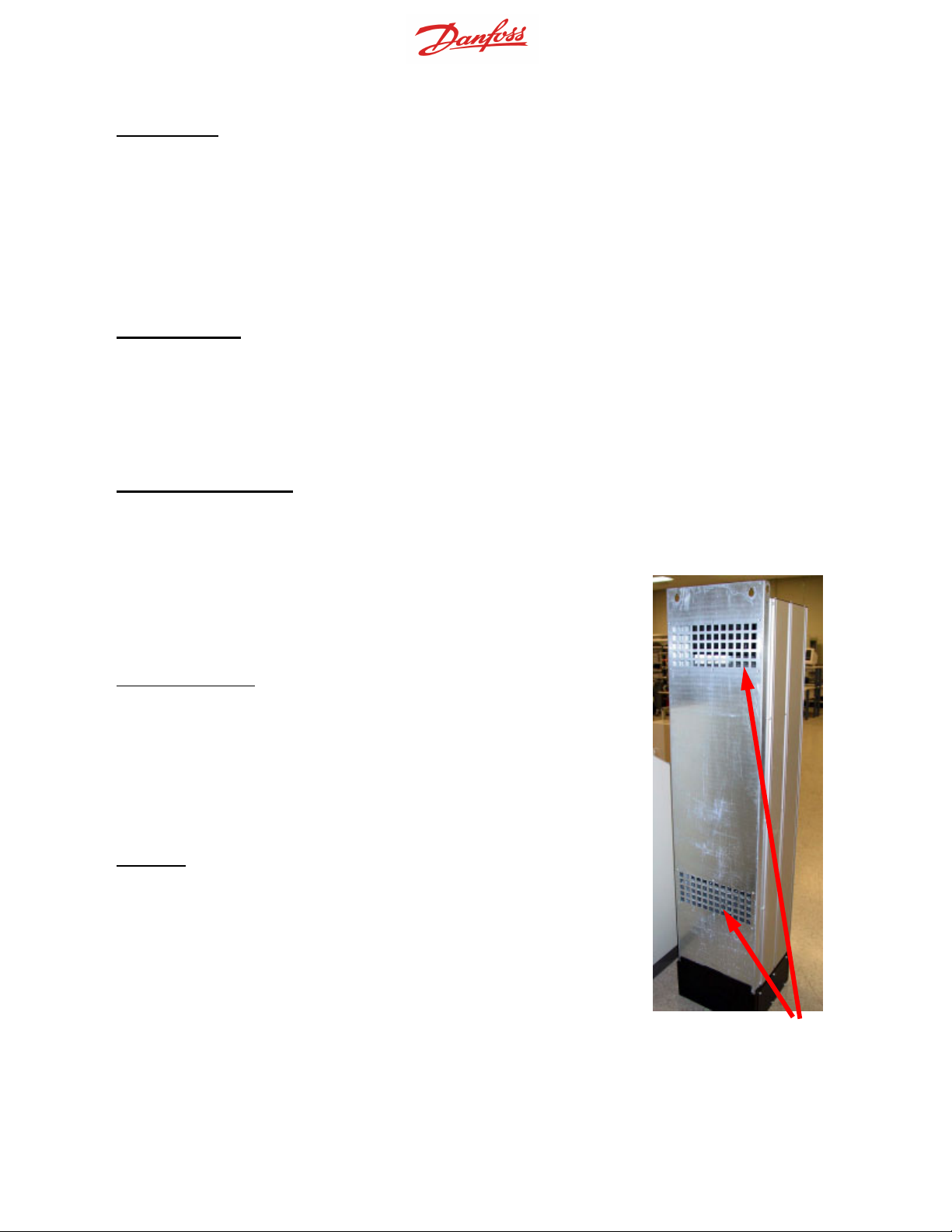
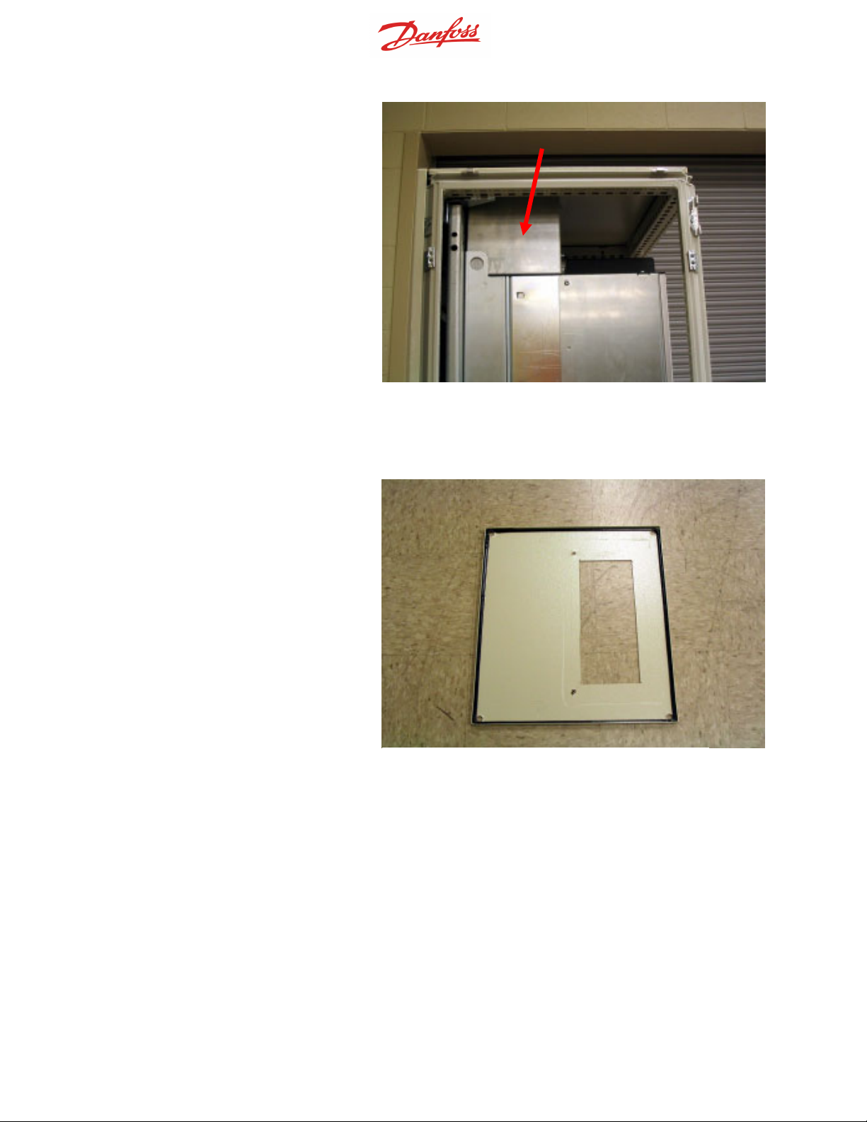
Install gasket material on the back openings of
the drive (Photo 1) prior to installation on the enclosure back panel.
D3 and D4 frames
: Use the template provided
with the kit (175R5639) to determine the drive
location on the back panel of the enclosure. The
template is referenced to the top-left corner of the
back panel. Therefore the template may be used
with any size back panel and both the 1800 mm
and 2000 mm high enclosures.
E2 frame
: Use the measurements on Drawing
175R1037, Sheet 2 to determine the drive location.
Photo 1. Drive openings o n rear are not
used in this application.
MI.38.H1.02 - VLT® is a Danfoss Registered Trademark 2
Page 3
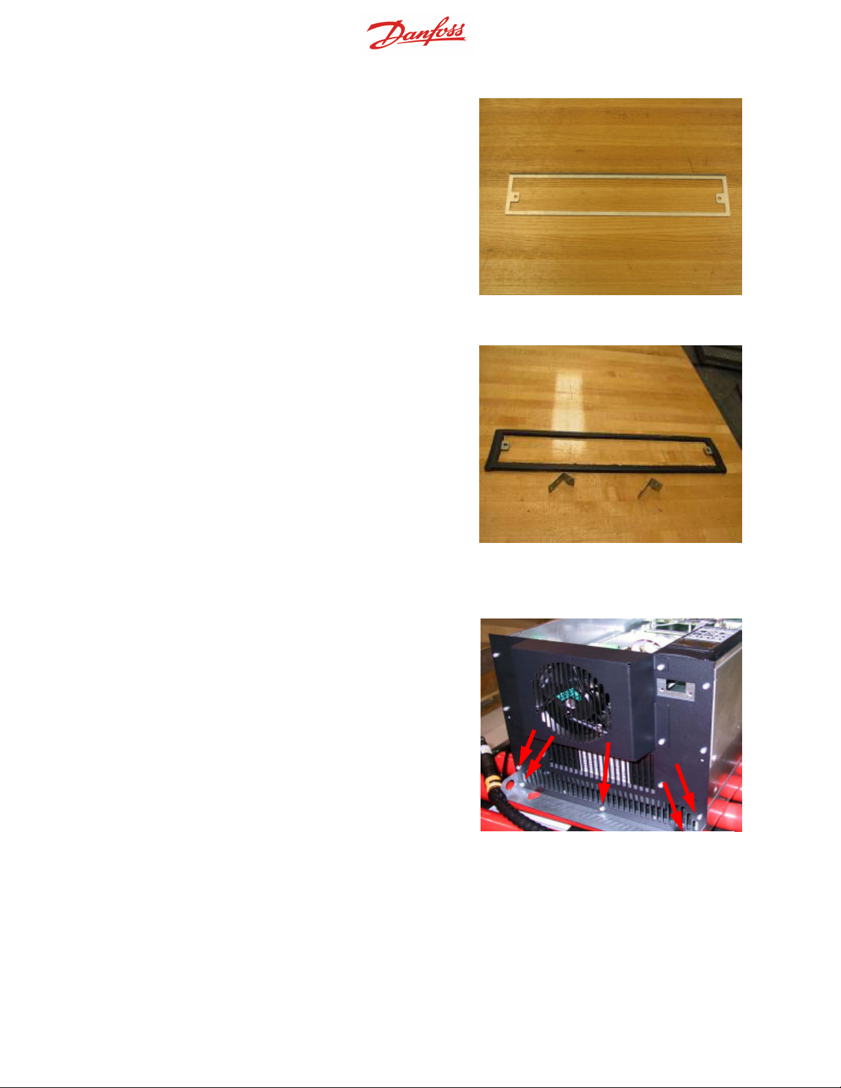
Prior to installing the back panel in the enclosure,
apply the gasket on both sides of the bottom duct
adapter as shown in Photos 2 and 3.
Photo 2. Bottom duct adapter
Before installing the back panel with the drive in
the enclosure, remove and discard the rear-most
screws (Photo 4) that are located on the top cover
of the drive. The holes will be used to fasten the
top ductwork with longer screws provided with the
kit.
Photo 3. Bottom duct adapter w/
Photo 4. Top of IP00/Chassis drive.
MI.38.H1.02 - VLT® is a Danfoss Registered Trademark 3
Page 4
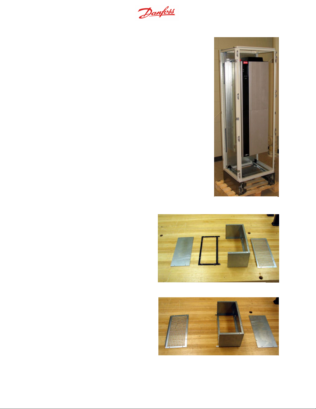
Install the backpanel in the enclosure (Photo 5). Use brackets
supplied by the enclosure manufacturer (minimum one per side
at the middle of the drive) with appropriate support strip for
additional support of the backpanel. For the D4 frame use two
supports per side. Consult the enclosure manufacturer manual
for additional support requirements if additional components are
mounted on the same back panel.
The top duct work cover is composed of
the following pieces as shown in Photo 6.
From left to right:
• top duct closing plate
• drive bracket
• duct
• vented top cover
Install the drive bracket onto the duct.
Photo 5. Drive installed
in cabinet—D4 Frame.
Photo 6. Top duct assembly.
Photo 7. The top duct work partially assembled with bottom flange.
MI.38.H1.02 - VLT® is a Danfoss Registered Trademark 4
Page 5
Temporarily install the top duct section as shown in Photo 8. Use the
top duct cover piece to mark the enclosure top for the opening. Alternately, Drawing 175R5639 can be
used to mark the enclosure for cut-
Cut the enclosure top. Do not apply
gasket to enclosure top (the gasket
is part of the duct work).
Photo 8. Top duct work and enclosure top installed.
Photo 9. Enclosure top with cutout.
MI.38.H1.02 - VLT® is a Danfoss Registered Trademark 5
Page 6

Assemble the top duct as shown in
Photos 10, 11 and 12. Gasket is applied to several surfaces as shown
(refer to drawing 175R5631 Sheet 2,
exploded view of components). The
top duct closing plate is left off for the
installation of the duct work on the
drive.
Closing plate
Photo 10. Top duct assembled with gasket.
Photo 11. Gasket applied to both sides drive
bracket and grated cover.
Photo 12. Top duct ready to be installed on drive.
MI.38.H1.02 - VLT® is a Danfoss Registered Trademark 6
Page 7

The top duct work is attached to the
drive using existing holes on the top
cover of the drive. Use the 5 longer
screws (supplied with kit) to install
the top duct work. The duct work will
fit over the drive mounting bolts.
Once the duct work is attached to the
drive, the duct closing plate can be
attached. The top duct work assembly is complete.
Photo 13. Gasket folds over the edge to form seal
between the duct and top vented cover.
Photo 14. Top duct installed.
MI.38.H1.02 - VLT® is a Danfoss Registered Trademark 7
Page 8

Install top duct-cover assembly using the longer T25 screws provided
with the kit in the drive top cover
holes. Reference Photos 15.
Apply the gasket to the top duct
closing plate. Reference Photo 16.
Photo 15. Top duct installed.
Install the duct closing plate. Reference Photo 17.
MI.38.H1.02 - VLT® is a Danfoss Registered Trademark 8
Photo 16. Top duct closing plate with gasket.
Photo 17. Top duct closing plate installed.
Page 9

Install the top of the enclosure. Reference Photos 18 and 19.
Top duct installation is complete.
Photo 18. Enclosure top installed.
Photo 19. Top view of enclosure.
MI.38.H1.02 - VLT® is a Danfoss Registered Trademark 9
Page 10

MI.38.H1.02 - VLT® is a Danfoss Registered Trademark 10
Page 11

MI.38.H1.02 - VLT® is a Danfoss Registered Trademark 11
Page 12

MI.38.H1.02 - VLT® is a Danfoss Registered Trademark 12
Page 13

MI.38.H1.02 - VLT® is a Danfoss Registered Trademark 13
Page 14

MI.38.H1.02 - VLT® is a Danfoss Registered Trademark 14
Page 15

MI.38.H1.02 - VLT® is a Danfoss Registered Trademark 15
 Loading...