

Page 1
Technical Information
ATEX certified
Axial piston pump, variable displacement
D1P130/D1P145/193/260
www.danfoss.com
Page 2
Technical Information
ATEX certified D1P 130/145/193/260
Revision history Table of revisions
Date Changed Rev
September 2021 Fixed typo 0202
August 2021 Added size 193/260, updated model code, and replaced the nameplate 0201
February 2020 Updated cover image and changed document number from BC00000404 0102
July 2018 first edition 0101
2 | © Danfoss | September 2021 BC274750280114en-000202
Page 3

Technical Information
ATEX certified D1P 130/145/193/260
Contents
General information
ATEX Introduction............................................................................................................................................................................4
Explosive atmosphere.....................................................................................................................................................................4
Explosion triangle....................................................................................................................................................................... 4
General zone classification...................................................................................................................................................... 4
Equipment category and zones.............................................................................................................................................5
Contents of marking.................................................................................................................................................................. 6
Marking of Danfoss D1 pumps...............................................................................................................................................7
Production place and date of pump....................................................................................................................................8
Example ATEX label - D1P........................................................................................................................................................8
Maximum surface temperature
Viscosity and temperature for D1P pump.............................................................................................................................10
Model Code
Model code.......................................................................................................................................................................................11
Displacement, rotation and product version.......................................................................................................................12
Control types................................................................................................................................................................................... 12
Input shaft options........................................................................................................................................................................ 12
Mounting flange options............................................................................................................................................................ 13
End cap and main port options................................................................................................................................................ 13
Auxiliary mounting flange options..........................................................................................................................................13
Power control settings.................................................................................................................................................................14
Pressure compensated control settings................................................................................................................................14
Load sensing control settings................................................................................................................................................... 15
Hydraulic displacement control setting................................................................................................................................ 15
Maximum and minimum displacement settings............................................................................................................... 15
Minimum displacement settings..............................................................................................................................................15
Special hardware and features..................................................................................................................................................15
Tandem pump information........................................................................................................................................................16
Technical specifications
Ambient temperature.................................................................................................................................................................. 17
Oil types / Operating fluids.........................................................................................................................................................17
Mineral oils..................................................................................................................................................................................17
Oil temperature.........................................................................................................................................................................17
Viscosity........................................................................................................................................................................................17
Displacement Limiter
Displacement limiter setting..................................................................................................................................................... 18
©
Danfoss | September 2021 BC274750280114en-000202 | 3
Page 4
Ignitable
substance (Gas)
Oxygen Source of ignition
(Spark or heat)
P301 800
Technical Information
ATEX certified D1P 130/145/193/260
General information
ATEX Introduction
The ATEX Directive 2014/34/EU specifies the minimum safety requirements for equipment intended for
use in potentially explosive atmospheres in European Union member states. ATEX is derived from the
French term ATmosphères EXplosives.
Hydraulic pump are designed for mobile and stationary applications. Some pump are used in related
applications, where locations are classified as hazardous areas.
The equipment intended for use in hazardous areas are divided into two groups:
Group I: Equipment intended for use in underground parts of mines (mining equipment).
Group II: Equipment intended for use in other places than mines (non-mining equipment).
The Danfoss hydraulic pump, type D1P are intended for use in Group II applications.
Explosive atmosphere
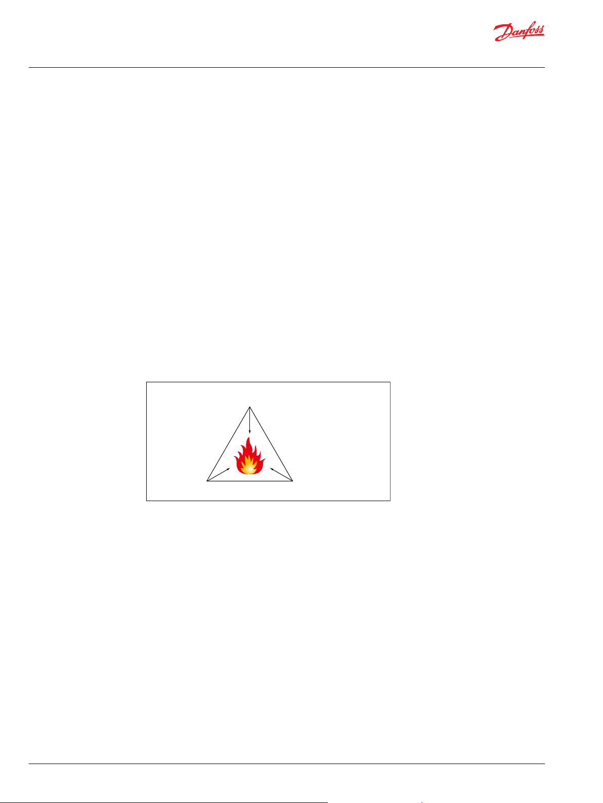
Explosion triangle
A “hazardous area” is defined as an area in which the atmosphere contains, or may contain in sufficient
quantities, flammable or explosive gases, dusts or vapours. In such an atmosphere a fire or explosion is
possible when three basic conditions are met. This is often referred to as the “hazardous area” or
“explosion” triangle.
An atmosphere with the potential to become an explosive atmosphere during operating conditions
and/or under the influence of the surroundings is defined as a potentially explosive atmosphere.
Products covered by directive 2014/34/EU are defined as intended for use in potentially explosive
atmospheres. Removing one of the elements eliminates all risk of explosion.
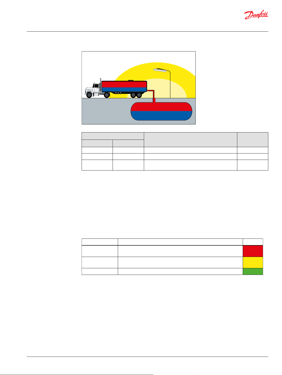
General zone classification
Directive 99/92/EC divides the Hazardous areas into zones and defines criteria by which products are
categorized within these zones; Zone 0 / 20 is the most restrictive and Zones 1 / 21 and 2 / 22 are less
restrictive. The following table describes the zones in an installation where there is a potential for
explosive atmospheres. The owner of the installation must analyze and assess the area in which the
explosive gas/dust mixture may occur, and if necessary must divide it into zones. This process of zoning
then allows the correct plant and equipment to be selected for use in the area.
4 | © Danfoss | September 2021 BC274750280114en-000202
Page 5
Zone 0
Zone 0
Zone 2
Zone 1
F301 801
Degree of protection Protection
Category
Very high Two independent protection measures or safe if two errors occur
independently
Category 1
High
Safe in normal operation and in anticipated case of commonly
occurring errors
Category 2
Normal Safe in normal operation
Category 3
P301 802
Technical Information
ATEX certified D1P 130/145/193/260
General information
Zones Presence of potentially explosive atmosphere Type of risk
Gas (G) Dust (D)
0 20 Present continuously or for long periods Permant
1 21 Likely to occur in normal operation occasionally Potential
2 22 Not likely to occur in normal operation but. If it does
occur, will persist for a short period of time
Minimal
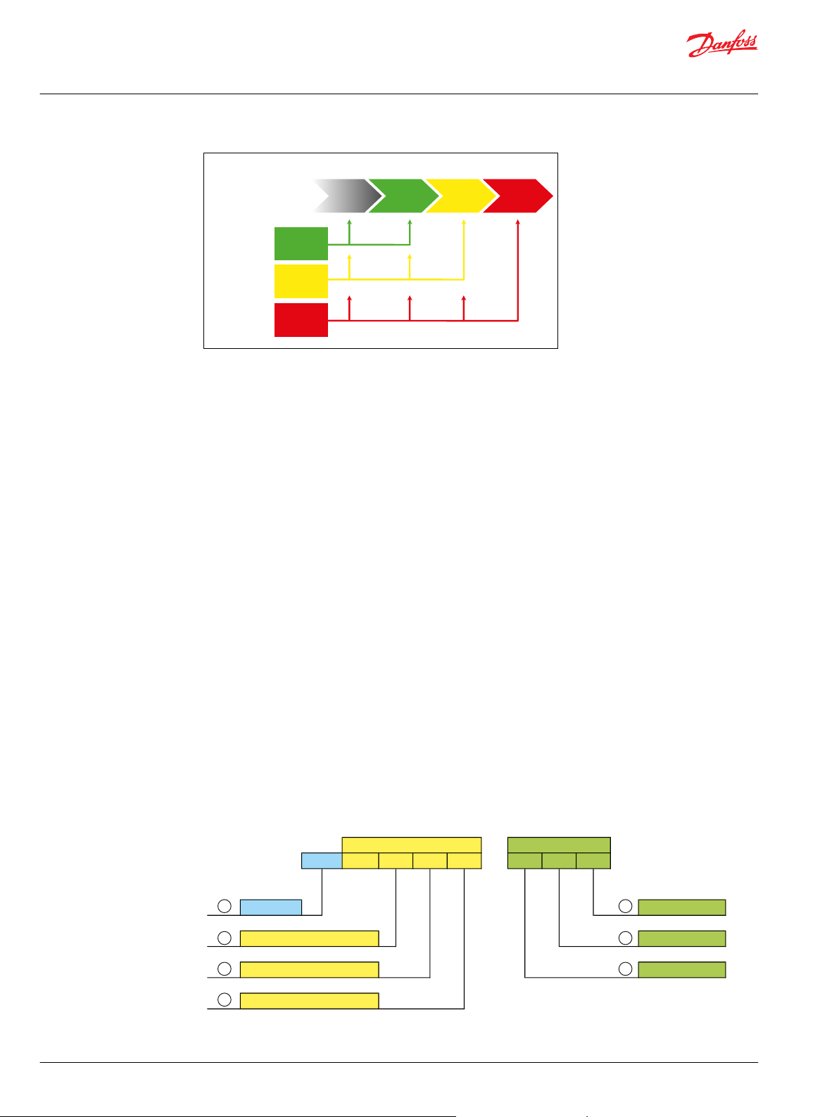
Equipment category and zones
Mechanical components with potential ignition sources e.g. components containing non-conductive
materials or layers or components with hot surface are covered by the ATEX-directive.
Non-mining equipment for potentially explosive atmosphere is classified as:
Equipment Group II – this group comprises three categories according to the level of safety provided:
•
Category 1
•
Category 2
•
Category 3
Category 1 equipment has the highest degree of protection – see the following below.
These products have to fulfil all requirements in the ATEX directive, and have to be marked with the
required “Ex” marking.
Equipment located in zone specified areas must fulfil the following requirements (see also the following
figure):
Category 3 – approved equipment can be installed in hazardous areas zone 2 / 22 and outside zone
•
categorized areas.
Category 2 – approved equipment can be installed in hazardous areas zone 1 / 21, zone 2 / 22 and
•
outside zone categorized areas.
©
Danfoss | September 2021 BC274750280114en-000202 | 5
Category 1 – approved equipment can be installed in hazardous areas zone 0 / 20, zone 1 / 21, zone
•
2 / 22 and outside zone categorized areas.
Page 6
Zone 0Zone 1Zone 2
No requirementsts
Hazards area
Catagory
3
Catagory
2
Catagory
1
ATEX
Directive
Equipment
group II
P301 803
Ex
CE-marking Temperature class
Equipment group Gas Group
Equipment Category Protection type
Nature of atmosphere
Spe cifi c markin g Add itiona l m arki ng
CE II 2 G c II C T4
1
2
3
7
6
5
4
P301 805
Technical Information
ATEX certified D1P 130/145/193/260
General information
Contents of marking
The rules for the marking of systems, equipment and components are uniformly defined in the standards
relating to the general technical requirements – EN 13463-1 for mechanical equipment.
A priority for all Ex equipment and protective systems is that the marking should show the areas of their
designated use. Components covered within the scope of the ATEX directive have to be CE-marked, and
marked with the specific “Ex”-sign.
Principle
The marking must indicate the following:
•
The manufacturer who has put the item of equipment on the market
•
Manufacturer’s type identification
•
Year in which the equipment was manufactured
•
A serial number
And further the ignition protection marking
•
Symbol of the equipment group and category (M1 or M2 for group I mining equipment, or 1 or 2 or 3
for Group II non-mining equipment).
Additionally for Group II equipment only:
1. The letter “G” where explosive atmospheres caused by gases, vapours or mists are concerned;
and/or
2. The letter “D” where explosive atmospheres caused by dusts are concerned.
•
Type of ignition protection system.
•
Where appropriate, symbol of explosion group of the equipment.
•
For Group II equipment, the symbol indicating the temperature class or the maximum surface
temperature in °C, or both.
6 | © Danfoss | September 2021 BC274750280114en-000202
Page 7

Technical Information
ATEX certified D1P 130/145/193/260
General information
Callout Description
1 CE marking
Specific marking
2 Equipment group I - Mining
3 Equipment category 1 (zone 0/20)
4 Nature of atmosphere G - Gas
Additional marking
5 Protection type fr - Protection by flow restricting enclosure
6 Gas group IIA
7 Temperature class
II - Non-mining
2 (zone 1/21)
3 (zone 2/22)
D - Dust
d - Protection by flameproof enclosure
c - Protection by constructional safety
b - Protection by control of ignition sources
p - Protection by pressurized enclosures
k - Protection by liquid immersion
IIB
IIC
Equipment without any explosion group maring can be used for
explosive atmosphere of explosive group IIA, IIB and IIC provided
the equipment is not marked for specific atmosphere.
T1 to T6
TX; where the maximum surface temperature depends not on
the equipment itself, but mainly on operating conditions (like
heated fluid) the relevant information shall be given in the
instruction for use in order to inform the user about this special
situation.
Marking of Danfoss D1 pumps
The Danfoss hydraulic pumps are marked as equipment for Group II, category 2 for gas and dust
environment and with ignition protection constructional safety and liquid immersion.
Temperature class/Maximum surface temperature depends on the operating conditions (ambient and
fluid temperature).
ATEX marking
Marking For model code option
CE Ex II 3G Ex h IIA T3 Gc AN3 (temperature class T3)
CE Ex II 3G Ex h IIA T4 Gc AN4 (temperature class T4)
CE Ex II 3G Ex h IIA T5 Gc AN5 (temperature class T5)
1
See Model Code for additional information.
1
See Viscosity and temperature for D1P pump on page 10 for more information about temperature classes.
For detailed information on selecting the appropriate T-codes, please see D1P ATEX User Manual,
BC376161003883.
©
Danfoss | September 2021 BC274750280114en-000202 | 7
Page 8

Technical Information
ATEX certified D1P 130/145/193/260
General information
Production place and date of pump
The production location and date of the pump is shown at the first 5 digits of the serial no.
Example: Serial no: N45123094
Five first digits are N4512
N is the manufacturing location (N=Nordborg ; H = Haiyan(China))
4 is the year (It stands for the last digit in the possible decade).
51 is the week
2 is the day (2 = Tuesday)
The last four digits are a consecutive number.
The ATEX certification of the units are done under the scope of:
"Directive 2014/34/EU of the European Parliament and of the Council of 26 February 2014 on the
harmonisation of the laws of the Member States relating to equipment and protective systems intended for use
in potentially explosive atmospheres."
With following parameters:
•
Equipment group: II
•
Zone: 2 (gas)
•
Equipment Category: 3G
•
Temperature class: T3...T5
•
Explosion protection group: II A
According to this classification, the Conformity Assessment Procedure has to be executed according to
Directive 2014/34/EU, annex VIII, Modul A: Internal Production Control (see article 13, section 1 (c)) The EU
declaration of conformity has to be prepared and issued with regard to annex X of /1/. The “Essential
Health and Safety Requirements” defined by /1/, annex II, have to be considered.
Example ATEX label - D1P
Examples of ATEX pump labels – Pump produced in People's republic of China
1. Manufacturer
2. Location of production
3. ATEX code
8 | © Danfoss | September 2021 BC274750280114en-000202
Page 9

Technical Information
ATEX certified D1P 130/145/193/260
General information
4. Material number
5. Model code, including unit and displacement
6. Production code
©
Danfoss | September 2021 BC274750280114en-000202 | 9
Page 10

W
W
Technical Information
ATEX certified D1P 130/145/193/260
Maximum surface temperature
Viscosity and temperature for D1P pump
Features Data
Viscosity
Temperature
1)
Intermittent = Short term t < 3 min per incident.
2)
Cold start = Short term t < 3 min; p ≤ 30 bar; n ≤ 1000 min-1(rpm); please contact Danfoss Power Solutions
especially when the temperature is below -25 °C [-13 °F].
3)
Must not be exceeded locally either (e.g. in the bearing area) . The temperature in the bearing area is (depending
on pressure and speed ) up to 5 °C [41 °F] higher than the average case drain temperature.
Above maximum surface temperatures are without any deposited dust on the product. The possible
insulation effect of a dust layer on the surface has to be taken into account by the safety margin to the
minimum ignition temperature of the dust concerned. For up to 5 mm [1.97 in] layer thickness the safety
margin is 75°C [167°F]. For further information please see IEC 60079-14.
Intermittent
Minimum 7 mm2/sec [49 SUS]
Recommended range 16-36 mm2 [81-168 SUS]
Maximum (cold start)
Minimum (cold start)
Maximum intermittent
1)
2)
2)
1)
5 mm2/sec [42 SUS]
1600 mm2/sec [7416 SUS]
-40°C [-40°F]
115°C [239°F]
3)
Warning
The above operating temperatures (ambient and oil) of the pump must be guaranteed by the end user.
Warning
It is compulsory to use oils whose inflammable degree is at least 50K above the maximum surface
temperature of the pump. See also Oil types / Operating fluids on page 17.
10 | © Danfoss | September 2021 BC274750280114en-000202
Page 11

D 1 P 2 6 0 R A T P E 2 T E 4 Y 3 B 1 1 1 5 3 4 0 N N N N F S 0 5 N N N NN N
Series
Product
type
Displacement
A B C D E F G H J K L M N P R S
Rotation
Product version
Control type
Input shaft
Endcap
Power control setting
Pressure compensated control setting
Load sensing control setting
Hydraulic disp control start pressure setting
Max displacement setting
Min displacement setting
Special hardware
Special feature
Mounting flange
Auxiliary flange
Technical Information
ATEX certified D1P 130/145/193/260
Model Code
D1P model code
The below illustration and the following sections describe how to identify parts of the model code and
availability of certain part options based on frame size.
Example model code; D1P 260 shown
©
Danfoss | September 2021 BC274750280114en-000202 | 11
Page 12

W
Technical Information
ATEX certified D1P 130/145/193/260
Model Code
D1P 130-260 displacement, rotation and product version
Displacement
Code Description 130 145 193 260
130 130 cm3 [7.93 in3] max. displacement per revolution
145 145 cm3 [8.85 in3] max. displacement per revolution
193 193 cm3 [11.78 in3] max. displacement per revolution
260 260 cm3 [15.87 in3] max. displacement per revolution
Rotation
Code Description 130 145 193 260
R Clockwise [CW]
L Counter Clockwise [CCW]
Product Version
Code Description 130 145 193 260
A
D1P 130-260 control types
Code Description 130 145 193 260
NPNN Pressure Compensated Control
NPSN Pressure Compensated Control + Load Sensing Control
NPNR Pressure Compensated Control + Remote Pressure Compensated Control
TPSN Power Control + Pressure Compensated Control + Load Sensing Control
TPH1 Power Control + Pressure Compensated Control
Control Code Explanation:
•
First digit: Power control (Torque control) , "N" means no power control.
•
Second digit: Pressure compensated control, "N" means no pressure compensated control.
•
Third & Fourth digits: Proportional displacement control or Load sensing control , "NN" means no
control in either category.
Warning
A relief valve is required to be installed in the pump outlet for additional system protection. Failure to
install the relief valve can lead to system damage and/or injury.
D1P 130-260 input shaft options
Code Description 130 145 193 260
T 130/145/193: Spline, DIN 5480 W50 x 2 x 30 x 24 x 9g;
260: Spline, DIN 5480 W60 x 2 x 30 x 28 x 9g;
Shaft Seal Material: FKM
S Spline, SAE J744 1 3/4in, 13T 8/16 DP;
Shaft Seal Material: FKM
12 | © Danfoss | September 2021 BC274750280114en-000202
Page 13

Technical Information
ATEX certified D1P 130/145/193/260
Model Code
Code Description 130 145 193 260
A 193: Spline, SAE J744 2in, 15T 8/16 DP;
260: Spline, SAE J744 2 1/4in, 17T 8/16 DP;
Shaft Seal Material: FKM
P Straight Keyed DIN 6885,
130/145: AS14 x 9 x 80
193: AS16 x 10 x 100
260: AS18 x 11 x 100
Shaft Seal Material: FKM
*
K
SAE J744 (D/E) 3in straight keyed shaft
0.4375x3.000in
*
There is no impeller option for sizes 130 and 145 with this shaft.
D1P 130-260 mounting flange options
Code Description 130 145 193 260
D4 SAE J744 152-4 (D)
E4 SAE J744 165-4 (E)
D1P 130-260 end cap and main port options
End cap and main ports
Code Description Rotation 130 145 193 260
Y1 Radial, side, flange ports
Inlet: 3in port, M16 x 2;
Outlet: 1 1/4in port, M14 x 2 SAE J518
With impeller
Y2 Radial, side, flange ports
Inlet: 3 1/2in port, M16 x 2;
Outlet: 1 1/2in port, M16 x 2 SAE J518
With impeller
Y3 Radial, side, flange ports
Inlet: 4in port, M16 x 2;
Outlet: 1 1/2in port, M16 x 2 SAE J518
With impeller
CW [R]
CCW [L]
CW [R]
CCW [L]
CW [R]
CCW [L]
D1P 130-260 auxiliary mounting flange options
Auxiliary mounting flange (through-drive flange)
Code Description 130 145 193 260
NN No auxiliary flange
A1 SAE J744 82-2 (A); Spline coupling: 5/8in 9T 16/32DP
A2 SAE J744 82-2 (A); Spline coupling: 3/4in 11T 16/32DP
A3 SAE J744 82-2 (A); Spline coupling: 7/8in 13T 16/32DP
B1 SAE J744 101-2 (B) ; Spline coupling: 7/8in 13T 16/32DP
B2 SAE J744 101-2 (B); Spline coupling: 1in 15T 16/32DP
BA SAE J744 101-2 (B); Spline coupling: 7/8in 13T 16/32DP; Adapter 90°
BB SAE J744 101-2 (B); Spline coupling: 7/8in 13T 16/32DP; Cover 45°
©
Danfoss | September 2021 BC274750280114en-000202 | 13
Page 14

P
setting@1500 rpm
= P
actual *
n
actual
1500
Technical Information
ATEX certified D1P 130/145/193/260
Model Code
Auxiliary mounting flange (through-drive flange) (continued)
Code Description 130 145 193 260
C5 SAE J744 127-2&4 (C) ; Spline coupling:1 1/4in 14T 12/24DP
C9 SAE J744 127-2&4 (C); Spline coupling: 1 3/4in 13T 8/16DP
D2 SAE J744 152-4 (D); Spline coupling: 1 3/4in 13T 8/16DP
D5 SAE J744 152-4 (D) ; Spline coupling: N50x2x30x24x9H
E2 SAE J744 165-4 (E) ; Spline coupling: N50 x 2 x 30 x 24 x 9H
E3 SAE J744 165-4 (E) ; Spline coupling: N60 x 2 x 30 x 28 x 9H
D1P 130-260 power control settings
Power control setting at 1500rpm (kW), “3 digit code”
1
Code
NNN No Power Control
XXX xxx kW between ranges specified below (For example: Code "090" means 90kW)
030-115 30-115 kW [40-154 hp] at 1500 rpm
035-155 35-155 kW [47-208 hp] at 1500 rpm
040-210 40-210 kW [54-282 hp] at 1500 rpm
1
For settings out of these ranges, please contact Danfoss Power Solutions.
2
Only increments of 5kW [6.7 hp] are allowed. E.g. 035, 040, 045, etc.)
Description 130 145 193 260
at 1500 rpm
2
2
2
If the speed is not 1500rpm, please make a conversion using the following formula, assuming constant
torque:
For example:
If actual power is 110 kW at 2100 rpm, the conversion to obtain the power control setting at 1500 rpm
should be 110*1500/2100=79, choose 080 option (round to closest 5 kW increment option).
D1P 130-260 pressure compensated control setting
Pressure compensated control setting (bar), “3 digit code”
*
Code
NNN No Pressure compensated control
XXX xxx bar between the range specified below (For example: Code "320" means 320
150~350 150~350 bar [2176~5076 psi] (Please select pressure compensated control setting
*
For settings out of these ranges, please contact Danfoss Power Solutions.
Description 130 145 193 260
bar [4641 psi])
in increments of 10 bar [145 psi]. E.g. 150 or 160 or 170, etc.)
14 | © Danfoss | September 2021 BC274750280114en-000202
Page 15

Technical Information
ATEX certified D1P 130/145/193/260
Model Code
D1P 130-260 load sensing control settings
L - Load Sensing Control Setting (bar), "2 digit code"
Code Description 130 145 193 260
NN No load sensing control
XX xx bar between the range specified below (For example: Code "25" means 25 bar
10~35*10~35 bar [145~508 psi] (Please select load sensing control setting in increments
*
For settings out of these ranges, please contact Danfoss Power Solutions. Range allowed for NPNR (Pressure compensated + Remote Pressure
compensated control) is 15-35 bar
D1P 130-260 hydraulic displacement control setting
Hydraulic displacement control start pressure setting, “2 digit code”
Code Description 130 145 193 260
NN No hydraulic displacement control
04-10 4-10 bar
[363 psi])
of 1 bar [14.5 psi]. E.g. 10 or 11 or 12, etc.)
D1P 130-260 maximum displacement settings
Maximum displacement setting, “2 digit code”
Code Description 130 145 193 260
FS Factory setting : 100%
1
XX
1
Please consider frame sizing and increments when selecting a maximum displacement setting (see displacement limiter for more information).
2
Only increments of 5% are allowed. (E.g. 70, 75, 80 etc.)
XX% of maximum displacement (For example: Code "90" means 90% of maximum
displacement)
2
D1P 130-260 minimum displacement settings
Minimum displacement setting, “2 digit code”
Code Description 130 145 193 260
FS 0% of maximum displacement limit setting
XX XX% of maximum displacement limit setting
1
Only increments of 5% are allowed. (E.g. 70, 75, 80 etc.)
1
If a different minimum displacement setting is required, please contact Danfoss Power Solutions.
D1P ATEX special hardware and features
Special features
Code Description 130 145 193 260
AN3 Factory Setting (black paint, ATEX tag T3, format A w/o filter)
AN4 Factory Setting (black paint, ATEX tag T4, format A w/o filter)
AN5 Factory Setting (black paint, ATEX tag T5, format A w/o filter)
©
Danfoss | September 2021 BC274750280114en-000202 | 15
Page 16

P400282
Control
Pump
Endcap
Control
Pump
Endcap
P400282
Control
Pump
Endcap
Control
Pump
Endcap
Control
Pump
Endcap
Technical Information
ATEX certified D1P 130/145/193/260
Model Code
D1P tandem pump information
Information about tandem pump direction and ordering instructions are found below.
Pump direction
Auxiliary pump
INDEX = 0°
Auxiliary pump
INDEX = 90°
When assembling a system the first
pump is always to be considered at 0°
INDEX as shown below.
Auxiliary pump
INDEX = 270°
Auxiliary pump
INDEX = 180°
For gear pump tandem angle information, please contact Danfoss Power Solutions.
Ordering tandem pumps
When ordering tandem pumps, the type designations of the 1st and 2nd pumps must be connected by a
“+”, and tandem pump angle should be given as indicated below.
Ordering example:
D1P193RATPE2TE4Y2E2090320NNNNFSFSNNNNNN +
D1P193RATPE2TE4Y2NN090320NNNNFSFSNNNNNN
Tandem angle 0° + 180°
16 | © Danfoss | September 2021 BC274750280114en-000202
Page 17

W
Technical Information
ATEX certified D1P 130/145/193/260
Technical specifications
Ambient temperature
Maximum ambient temperature depends on the requested ATEX class needed.
In general the ambient temperature should lie between -30 °C [-22 °F] and +90 °C [+210 °F] to ensure that
the shaft seal retains its sealing capacity.
Oil types / Operating fluids
In a hydraulic system the most important task of the oil is to transfer energy. At the same time the oil
must lubricate moving parts in hydraulic components, protect them from corrosion, and transport dirt
particles and heat out of the system. To ensure that hydraulic components operate without problems
and have long operating life it is therefore vital to select the correct oil type with the necessary additives.
Ratings and performance data are based on operating with hydraulic fluids containing oxidation, rust
and foam inhibitors. These fluids must possess good thermal and hydrolytic stability to prevent wear,
erosion and corrosion of pump components.
Mineral oils
For systems containing Danfoss hydraulic pumps, type D1P, mineral hydraulic oil with anti-wear
additives, type HLP [DIN 51524] or HM (ISO 11158) must be used. Mineral oils without anti-wear additives
or engine oils can also be used, provided operating conditions are suitable.
Warning
It is compulsory to use oils whose inflammable degree is at least 50K above the maximum surface
temperature of the pump. Maximum surface temperature for Group IIG and IID can be found under:
Viscosity and temperature for D1P pump on page 10.
Oil temperature
Maximum oil temperature depends on the requested ATEX class needed (in this case T3)..
Under normal operating conditions it is recommended to keep the temperature in the range of 30 °C [86
°F] and 60 °C [140 °F].
Fluid temperature affects the viscosity of the fluid and resulting lubricity and film thickness. High
temperatures can also limit seal life, at most non-metallic materials are adversely affected by use at
elevated temperatures.
Fluids may break down or oxidize at high temperature, reducing their lubricity and resulting in reduced
life of the unit. Oil life is greatly reduced if its temperature exceeds +60 °C [+140 °F]. As a general rule, oil
life is halved for each 8 °C [46 °F] its temperature exceeds +60 °C [+140 °F].
Viscosity
Maintain fluid viscosity within the recommended range for maximum efficiency and bearing life.
Minimum viscosity should only occur during brief occasions of maximum ambient temperature and
severe duty cycle operation. Maximum viscosity should only occur at cold start. Limit speeds until the
system warms up.
Fluid viscosity limits
Conditions mm2/s (cSt) SUS
Minimum 12 66
Continuous 20 - 80 98 - 370
Maximum 1500 6950
We recommend the use of an oil type having a viscosity of 35 mm2/s at the actual operating temperature.
©
Danfoss | September 2021 BC274750280114en-000202 | 17
Page 18

P400281
Maximum
displacement
limiter
Minimum
displacement
limiter
Technical Information
ATEX certified D1P 130/145/193/260
Displacement Limiter
D1P displacement limiter
Series D1 pumps feature maximum and minimum displacement limiters, which limit displacement
mechanically.
Maximum Displacement Limiter
Frame Setting range Displacement change per turn
130
145
193
260
Minimum Displacement Limiter
Frame Setting range Displacement change per turn
130
145
193
260
72 cm3 – 130 cm
72 cm3 – 145 cm
0 cm3 – 193 cm
56 cm3 – 260 cm
0 cm3 – 124 cm
0 cm3 – 124 cm
0 cm3 – 193 cm
0 cm3 – 260 cm
3
3
3
3
3
3
3
3
11 cm3/rev
11 cm3/rev
16 cm3/rev
19 cm3/rev
9 cm3/rev
9 cm3/rev
15 cm3/rev
18 cm3/rev
Displacement Limiter Cross-Section View
18 | © Danfoss | September 2021 BC274750280114en-000202
Page 19

Danfoss
Power Solutions GmbH & Co. OHG
Krokamp 35
D-24539 Neumünster, Germany
Phone: +49 4321 871 0
Danfoss
Power Solutions ApS
Nordborgvej 81
DK-6430 Nordborg, Denmark
Phone: +45 7488 2222
Danfoss
Power Solutions (US) Company
2800 East 13th Street
Ames, IA 50010, USA
Phone: +1 515 239 6000
Danfoss
Power Solutions Trading
(Shanghai) Co., Ltd.
Building #22, No. 1000 Jin Hai Rd
Jin Qiao, Pudong New District
Shanghai, China 201206
Phone: +86 21 2080 6201
Products we offer:
Hydro-Gear
www.hydro-gear.com
Daikin-Sauer-Danfoss
www.daikin-sauer-danfoss.com
Cartridge valves
•
DCV directional control
•
valves
Electric converters
•
Electric machines
•
Electric motors
•
Gear motors
•
Gear pumps
•
Hydraulic integrated
•
circuits (HICs)
Hydrostatic motors
•
Hydrostatic pumps
•
Orbital motors
•
PLUS+1® controllers
•
PLUS+1® displays
•
PLUS+1® joysticks and
•
pedals
PLUS+1® operator
•
interfaces
PLUS+1® sensors
•
PLUS+1® software
•
PLUS+1® software services,
•
support and training
Position controls and
•
sensors
PVG proportional valves
•
Steering components and
•
systems
Telematics
•
Danfoss Power Solutions is a global manufacturer and supplier of high-quality hydraulic and
electric components. We specialize in providing state-of-the-art technology and solutions
that excel in the harsh operating conditions of the mobile off-highway market as well as the
marine sector. Building on our extensive applications expertise, we work closely with you to
ensure exceptional performance for a broad range of applications. We help you and other
customers around the world speed up system development, reduce costs and bring vehicles
and vessels to market faster.
Danfoss Power Solutions – your strongest partner in mobile hydraulics and mobile
electrification.
Go to www.danfoss.com for further product information.
We offer you expert worldwide support for ensuring the best possible solutions for
outstanding performance. And with an extensive network of Global Service Partners, we also
provide you with comprehensive global service for all of our components.
Local address:
Danfoss can accept no responsibility for possible errors in catalogues, brochures and other printed material. Danfoss reserves the right to alter its products without notice. This also applies to products
already on order provided that such alterations can be made without subsequent changes being necessary in specifications already agreed.
All trademarks in this material are property of the respective companies. Danfoss and the Danfoss logotype are trademarks of Danfoss A/S. All rights reserved.
©
Danfoss | September 2021 BC274750280114en-000202
 Loading...