

Page 1
Technical Information
D1 High Power Open Circuit Pumps
Size 130/145/193/260
www.danfoss.com
Page 2

Technical Information
D1 High Power Open Circuit Pumps Size 130/145/193/260
Revision history Table of revisions
Date Changed Rev
December 2021 Updated shaft specifications drawings 0501
October 2021 Added new auxiliary mounting options, updated inlet pressure gauge port section,
corrected displacement setting sections
February 2021 Added angle sensor section for D1P 260 0305
June 2020 Changed document number from 'BC00000243' and 'L1426007' to 'BC157786485289' and
corrected shaft descriptions
June 2019 Updated Model Code chapter 0202
December 2018 Updated shaft torque specifications 0201
November 2018 Added shaft option K 0113
October 2018 Minor Update 0112
August 2018 Minor Update (Model Code) 0111
July 2018 Minor Update 0110
July 2018 Added NPNR Control 0109
June 2018 Major Update 0108
May 2018 Added units and drawing 0107
January 2017 Added Size 130 0106
September 2016 some update of drawing and numbers 0105
May 2016 Added Size 260 0104
0401
0304
March 2016 minor update 0103
February 2016 minor update 0102
January 2016 Converted to Danfoss layout - DITA CMS 0101
July 2015 Updated drawings AC
April 2015 Added 145 cc information AB
May 2014 First edition AA
2 | © Danfoss | December 2021 BC157786485289en-000501
Page 3

Technical Information
D1 High Power Open Circuit Pumps Size 130/145/193/260
Contents
General Information
Overview..............................................................................................................................................................................................6
Features and benefits..................................................................................................................................................................... 6
Typical applications.........................................................................................................................................................................6
Design...................................................................................................................................................................................................7
Technical Specifications
Pump specifications........................................................................................................................................................................ 9
Fluid specifications........................................................................................................................................................................10
D1P 260 angle sensor................................................................................................................................................................... 11
Angle sensor principle............................................................................................................................................................11
Location........................................................................................................................................................................................11
Angle sensor characteristics................................................................................................................................................. 12
Angle sensor electrical specifications............................................................................................................................... 13
Angle sensor calibration........................................................................................................................................................ 13
Angle sensor functionality.................................................................................................................................................... 14
Model Code
Model code.......................................................................................................................................................................................15
Displacement, rotation and product version.......................................................................................................................16
Control types................................................................................................................................................................................... 16
Input shaft options........................................................................................................................................................................ 17
Mounting flange options............................................................................................................................................................ 17
End cap and main port options................................................................................................................................................ 17
Auxiliary mounting flange options..........................................................................................................................................18
Power control settings.................................................................................................................................................................18
Pressure compensated control settings................................................................................................................................19
Load sensing control settings................................................................................................................................................... 19
Hydraulic displacement control setting................................................................................................................................ 19
Maximum and minimum displacement settings............................................................................................................... 19
Minimum displacement settings..............................................................................................................................................19
Special hardware and features..................................................................................................................................................20
Tandem pump information........................................................................................................................................................21
Parameters
Pressure............................................................................................................................................................................................. 22
Speed..................................................................................................................................................................................................22
Performance.....................................................................................................................................................................................23
Input power................................................................................................................................................................................ 23
Output flow.................................................................................................................................................................................25
Efficiency......................................................................................................................................................................................26
Fluid.................................................................................................................................................................................................... 27
Viscosity........................................................................................................................................................................................27
Temperature...............................................................................................................................................................................27
Fluid velocity.............................................................................................................................................................................. 27
Shaft torque ratings...................................................................................................................................................................... 28
Shaft load..........................................................................................................................................................................................28
Mounting flange loads.................................................................................................................................................................28
Auxiliary mounting pads.............................................................................................................................................................28
Estimating overhung load moments......................................................................................................................................29
Understanding and minimizing system noise.....................................................................................................................30
Installation........................................................................................................................................................................................30
Filtration............................................................................................................................................................................................ 30
Reservoir............................................................................................................................................................................................31
Sizing Equations............................................................................................................................................................................. 31
Control Type
NPNN (Pressure Compensated Control)................................................................................................................................32
NPSN (Pressure Compensated Control + Load Sensing Control).................................................................................34
NPNR (Pressure Compensated Control + Remote Pressure Compensated Control)............................................ 36
TPSN (Power Control + Pressure Compensated Control + Load Sensing Control)................................................38
©
Danfoss | December 2021 BC157786485289en-000501 | 3
Page 4

Technical Information
D1 High Power Open Circuit Pumps Size 130/145/193/260
Contents
NNES (Electric Displacement Control + Load Sensing Control)....................................................................................40
Solenoid Specification............................................................................................................................................................ 42
Standard EDC Valve................................................................................................................................................................. 43
NNES Priority.............................................................................................................................................................................. 43
TPE2/TPE5 (Power Control + Pressure Compensated Control + Electric Displacement Control).................... 44
TPE2/TPE5 Priority....................................................................................................................................................................44
NPE2/NPE0 (Pressure Compensated Control + Electric Displacement Control).....................................................45
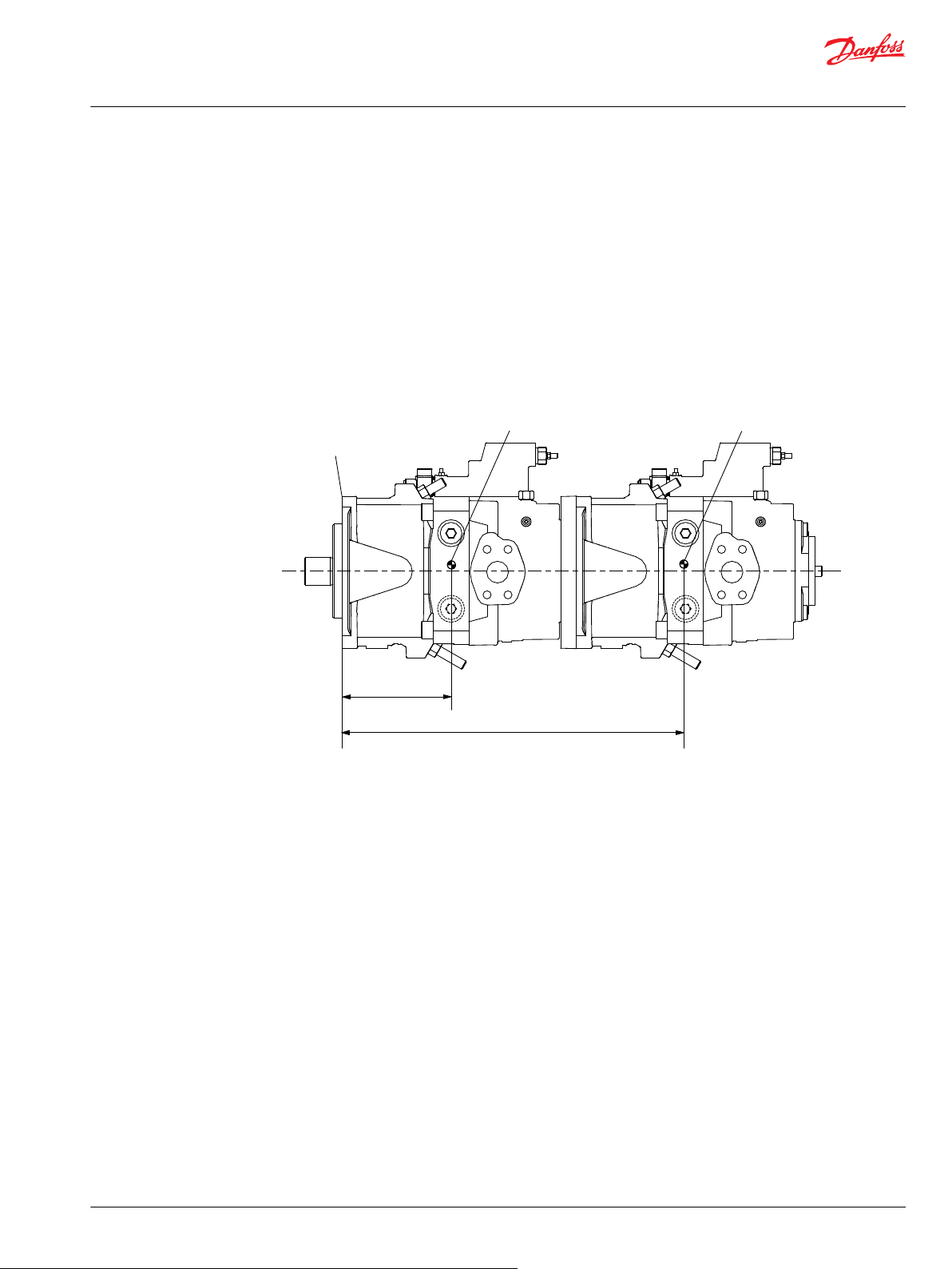
Installation Drawings
Size 130/145.....................................................................................................................................................................................46
Dimensions (mm) and port descriptions......................................................................................................................... 46
Size 130/145: TPSN w/o Charge Pump........................................................................................................................46
Size 130/145: TPE5 w/o Charge Pump.........................................................................................................................48
Size 130/145: TPSN w/ Charge pump ..........................................................................................................................50
Size 130/145: TPE5 w/ Charge Pump........................................................................................................................... 52
Input shaft................................................................................................................................................................................... 54
Shaft specifications.............................................................................................................................................................54
Aux mounting flange.............................................................................................................................................................. 56
Size 130/145: Option NN (No Coupling)..................................................................................................................... 56
Size 130/145: Option A1 (SAE-A, 9 teeth)................................................................................................................... 56
Size 130/145: Option A2 (SAE-A, 11 teeth).................................................................................................................57
Size 130/145: Option B1 (SAE-B, 13 teeth)................................................................................................................. 58
Size 130/145: Option B2 (SAE-B, 15 teeth)................................................................................................................. 58
Size 130/145: Option BA (SAE-B, 13 teeth).................................................................................................................59
Size 130/145: Option C5 (SAE-C, 14 teeth).................................................................................................................59
Size 130/145: Option D5 (SAE-D, 24 teeth)................................................................................................................ 60
Size 193..............................................................................................................................................................................................61
Dimensions (mm) and port descriptions......................................................................................................................... 61
Size 193: TPE2 w/ Charge Pump.....................................................................................................................................61
Size 193: TPSN w/ Charge Pump....................................................................................................................................63
Input shaft................................................................................................................................................................................... 65
Shaft specifications.............................................................................................................................................................65
Aux mounting flange.............................................................................................................................................................. 68
Size 193: Option NN (No Coupling).............................................................................................................................. 68
Size 193: Option A1 (SAE-A, 9 teeth)............................................................................................................................ 68
Size 193: Option A3 (SAE-A, 13 teeth)..........................................................................................................................69
Size 193: Option B1 (SAE-B, 13 teeth)...........................................................................................................................69
Size 193: Option B2 (SAE-B, 15 teeth)...........................................................................................................................70
Size 193: Option BA (SAE-B, 13 teeth) .........................................................................................................................71
Size 193: Option BB (SAE-B, 13 teeth).......................................................................................................................... 72
Size 193: Option C5 (SAE-C, 14 teeth).......................................................................................................................... 73
Size 193: Option C9 (SAE-C, 13 teeth).......................................................................................................................... 73
Size 193: Option D2 (SAE-D, 13 teeth)......................................................................................................................... 74
Size 193: Option D5 (SAE-D, 24 teeth)......................................................................................................................... 74
Size 193: Option E2 (SAE-E, 24 teeth)...........................................................................................................................75
Size 260..............................................................................................................................................................................................76
Dimensions (mm) and port descriptions......................................................................................................................... 76
Size 260: TPE2 w/ Charge Pump.....................................................................................................................................76
Size 260: TPSN w/ Charge Pump....................................................................................................................................78
Input shaft................................................................................................................................................................................... 80
Shaft specifications.............................................................................................................................................................80
Aux mounting flange.............................................................................................................................................................. 83
Size 260: Option A1 (SAE-A, 9 teeth)............................................................................................................................ 83
Size 260: Option A3 (SAE-A, 13 teeth)..........................................................................................................................83
Size 260: Option B1 (SAE-B, 13 teeth)...........................................................................................................................84
Size 260: Option B2 (SAE-B, 15 teeth)...........................................................................................................................84
Size 260: Option BA (SAE-B, 13 teeth)..........................................................................................................................85
Size 260: Option BB (SAE-B, 13 teeth).......................................................................................................................... 86
Size 260: Option C5 (SAE-C, 14 teeth).......................................................................................................................... 87
Size 260: Option C9 (SAE-C, 13 teeth).......................................................................................................................... 88
4 | © Danfoss | December 2021 BC157786485289en-000501
Page 5

Technical Information
D1 High Power Open Circuit Pumps Size 130/145/193/260
Contents
Size 260: Option D2 (SAE-D, 13 teeth)......................................................................................................................... 88
Size 260: Option D5 (SAE-D, 24 teeth)......................................................................................................................... 89
Size 260: Option E2 (SAE-E, 24 teeth)...........................................................................................................................89
Size 260: Option E3 (SAE-E, 28 teeth)...........................................................................................................................90
Inlet pressure gauge port............................................................................................................................................................91
Additional Information
Tandem with Danfoss pumps....................................................................................................................................................93
Tandem pump torque..................................................................................................................................................................93
Tightening torque..........................................................................................................................................................................94
Installation Notes
Below reservoir (standard)..........................................................................................................................................................95
Above reservoir...............................................................................................................................................................................96
Reservoir installation.................................................................................................................................................................... 97
Displacement Limiter
Displacement limiter setting..................................................................................................................................................... 98
©
Danfoss | December 2021 BC157786485289en-000501 | 5
Page 6

Technical Information
D1 High Power Open Circuit Pumps Size 130/145/193/260
General Information
D1P overview
The D1 pump series are high performance variable axial piston pumps designed primarily for open circuit
hydraulic systems used in heavy duty mobile applications.
Displacement options
•
130 cm3 [7.93 in3]
•
145 cm3 [8.85 in3]
•
193 cm3 [11.78 in3]
•
260 cm3 [15.87 in3]
Product highlights
•
Maximum working pressure: 350 bar [5076 psi], peak pressure (intermittent): 400 bar [5802 psi].
•
Input speed up to 2,500 rpm.
Control options
•
Mechanical power control
•
Electric power control
•
Pressure compensated control
•
Remote pressure compensated control
•
Electric proportional displacement control
•
Load sensing control
D1P features and benefits
D1P typical applications
Robust design for harsh conditions.
•
Swashplate, servo-controlled design, with proven reliability and performance.
•
Angled piston bore design improves self-priming capability.
•
The spherical valve plate and cylinder block interface provide stable cylinder block rotation, thus
•
achieving high efficiency.
Integral charge pump option allows the pump to run at higher speed and achieve good cold start
•
performance.
Full through-drive capability is suitable for adding axial piston pumps and gear pumps.
•
Optimized cradle bearing improves pump service life.
•
PLUS+1® compliant controls.
•
Can be used together in combination with other Danfoss Power Solutions products in the overall
•
hydraulic system, such as:
Pumps (S45, S90, H1P, gear pumps, etc.)
‒
PVG valves
‒
Motors (S90, H1B, etc).
‒
Concrete Machinery
•
Mining Machinery
•
Drilling Machinery
•
Material Handling
•
Marine and Off-shore Machinery
•
Oil Machinery
•
6 | © Danfoss | December 2021 BC157786485289en-000501
Page 7
1
2
3
4
5
6
7
8
9
10
11
12
13
14
15
16
Technical Information
D1 High Power Open Circuit Pumps Size 130/145/193/260
General Information
Excavators
•
Wheel Loaders
•
Industrial Hydraulics
•
Design
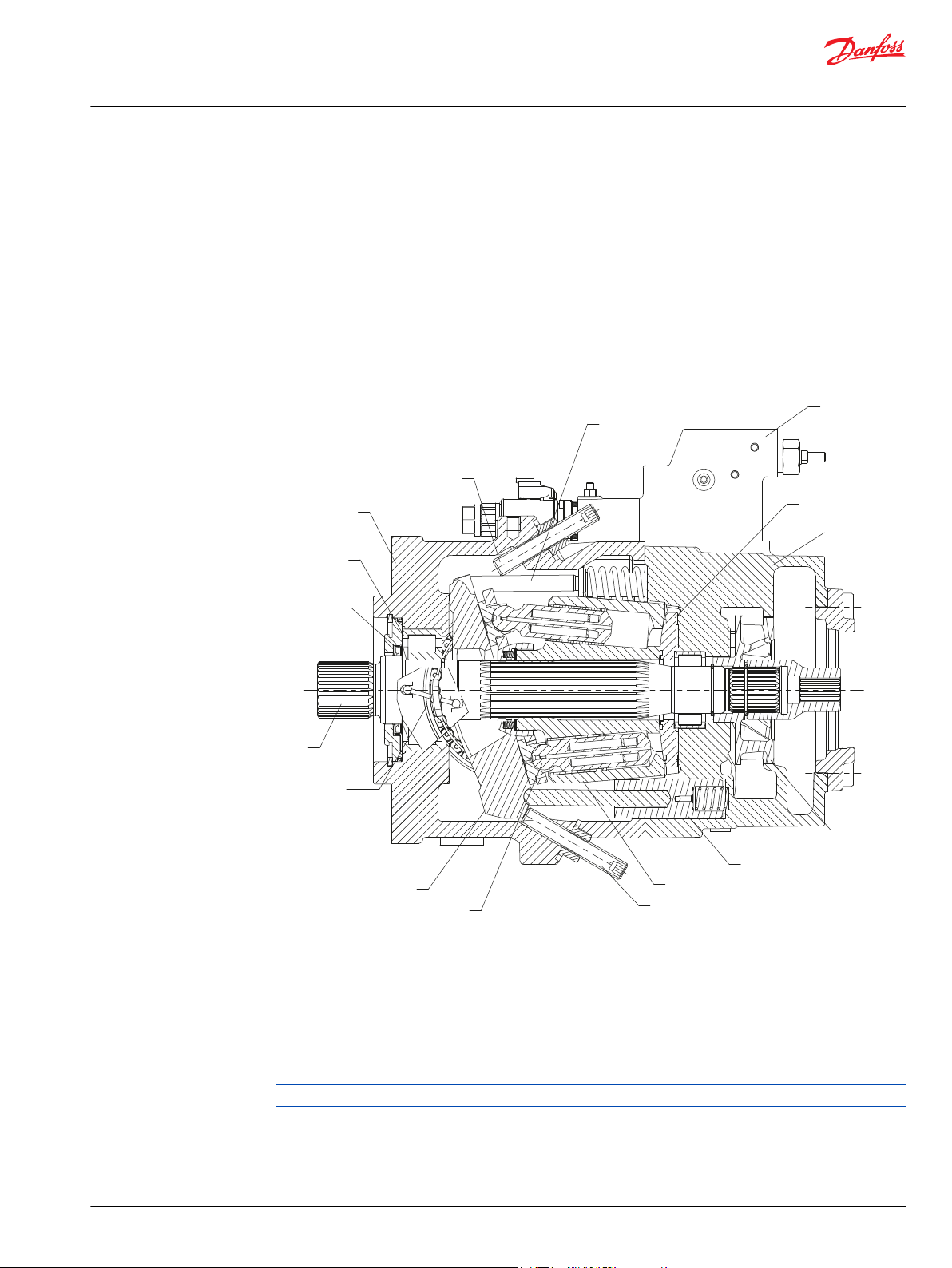
D1P sectional view
The cross sectional view of the D1P can be used to identify individual parts of the product.
Series D1 pump (w/charge pump) cross-section view
1. Shaft Seal 2. Roller Bearing 3. Housing
4. Minimum Displacement Limiter 5. Bias Piston 6. Control (TPE5/TPE2)
7. Valve Plate 8. End cap 9. Charge Pump
10. Servo Piston 11. Cylinder Block 12. Maximum Displacement Limiter
13. Piston 14. Swashplate 15. Swashplate Bearing
16. Input Shaft
Some internal parts may be different depending on frame size and options desired.
©
Danfoss | December 2021 BC157786485289en-000501 | 7
Page 8
MB
L3
S M4
L1 L2
Vg
max
Vg
min
P400268
Technical Information
D1 High Power Open Circuit Pumps Size 130/145/193/260
General Information
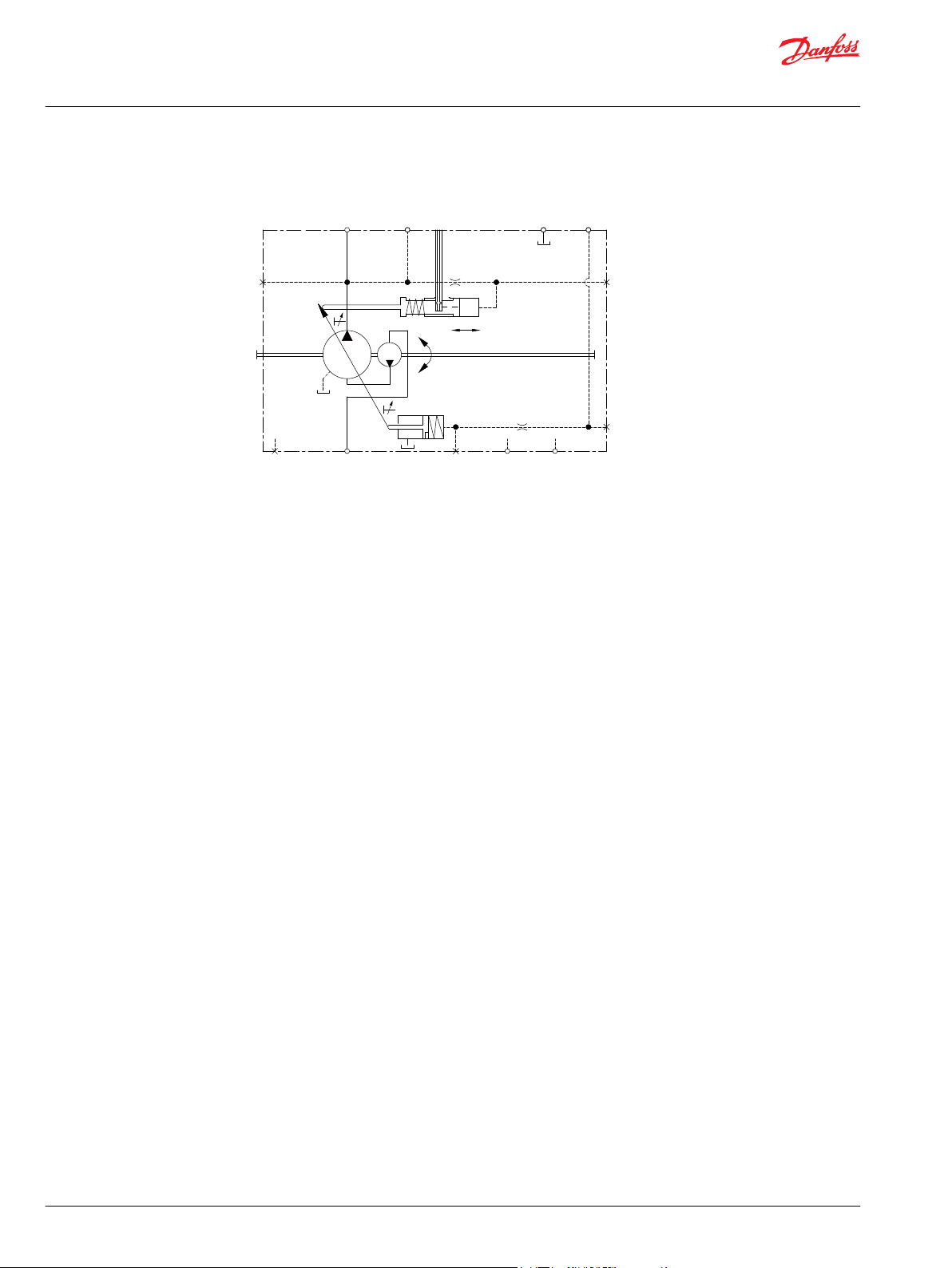
D1P schematic with charge pump
Basic schematic without control/with charge pump
The charge pump (see schematic) is a circulating pump with which the pump is charged and therefore
can be operated at higher speeds. This also improves cold starting at low temperatures and high viscosity
of the hydraulic fluid. The pressurized reservoir is therefore unnecessary in most cases. A reservoir
pressure of a max. 2 bar is permissible with charge pump.
8 | © Danfoss | December 2021 BC157786485289en-000501
Page 9
Technical Information
D1 High Power Open Circuit Pumps Size 130/145/193/260
Technical Specifications
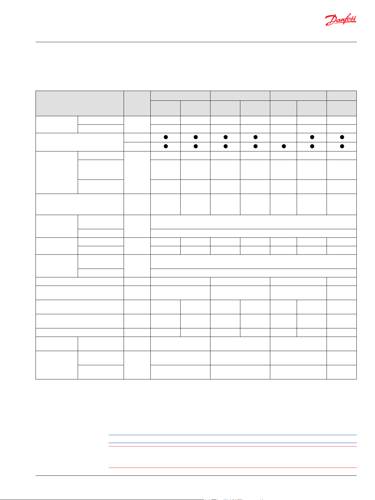
D1 130-260 pump specifications
(Theoretical values, without efficiency and tolerances; value rounded)
130 145 193 260
Features Unit
Displacement
Available rotation
Maximum
Minimum 0 0 0 0 0 0 0
cm3 [in3]
CCW [L]
CW [R]
Min.
Rated at max.
Input speed
Flow at max. speed & displacement (n
max. & Vg max.)
displacement (Vg
max.)
Maximum at Vg <
3
Vg max.
rpm
l/min
[US gal/
min]
System (working)
4
pressure
Inlet pressure
(absolute)
Case pressure
(absolute)
Max. working
pressure
bar [psi]
Max. pressure 400 [5802]
Minimum
Maximum 30 [435]
bar [psi]
Maximum above
inlet
bar [psi]
Maximum 2 [29]
Filling capacity L [US gal] 2.9 [0.77] 2.9 [0.77] 3.8 [1] 4.6 [1.3]
Torque at Vg max. & Δp = 350 bar N•m
[lbf•in]
Power at Q max. (max. flow) & Δp = 350
kW [hp] 159 [213] 190 [255] 186 [249] 211 [283] 248 [332] 281 [377] 349 [468]
bar
Mass moment of inertia of internal
rotating components
2
kg•m
[slug•ft2]
Mass kg [lb] 68 [150] 74 [163] 68 [150] 74 [163] 101 [222] 106 [234] 141 [311]
External shaft
loads
External moment
M
e
N•m
[lbf•in]
Vibratory
Mounting flange
load moments
1
The values apply at absolute pressure (Pabs) of at least 0.8 bar [11.6psi] at the suction port S and mineral hydraulic fluid.
2
The values apply at absolute pressure (Pabs) of at least 0.6 bar [8.7psi] at the suction port S and mineral hydraulic fluid.
3
The values apply at Vg ≤ Vg max or in case of an increase in the inlet pressure (Pabs) at the suction port S. Please refer to Inlet Pressure vs Speed Graph
(continuous)
Shock (maximum) 8692 [76930] 8692 [76930] 13782 [121980] 16338
N•m
[lbf•in]
at D1P speed overview on page 22
4
Applied pressures above maximum working pressure requires Danfoss application approval. Maximum (peak) pressure is the highest intermittent
(t<1s) outlet pressure allowed.
5
If the application requires the higher inlet pressure than 5 bar [72.5psi] (up to 30 bar [435psi]), please contact.Danfoss Power Solutions.
W/O
Impeller
W/ Impeller
W/O
Impeller
W/ Impeller
W/O
Impeller
W/ Impeller W/ Impeller
130 [7.93] 130 [7.93] 145 [8.85] 145 [8.85] 193 [11.78] 193 [11.78] 260 [15.87]
500 500 500 500 500 500 500
2200
1
2500
2
2200
1
2500
2
2200
1
2500
1
2300
2
2500 2500 2200 2500 2500 2500 2300
286 [76] 325 [86] 319 [84] 363 [96] 425 [112] 483 [128] 598 [158]
350 [5076]
0.8 [11.6] 0.6 [8.7] 0.8 [11.6] 0.6 [8.7] 0.8 [11.6] 0.6 [8.7] 0.6 [8.7]
5
2 [29] 30 [435] 2 [29] 30 [435] 2 [29] 2 [29]
1.2 [17.4]
724 [6408] 808 [7151] 1075 [9515] 1448
[12816]
0.0299
[0.0221]
0.0306
[0.0226]
0.0299
[0.0221]
0.0306
[0.0226]
0.0547
[0.0403]
0.0576
[0.0426]
0.2080
[0.1537]
476 [4213] 476 [4213] 822 [7275] 1081 [9568]
4553 [40297] 4553 [40297] 6286 [55636] 8477
[75027]
[144603]
Counterclockwise (CCW) & Clockwise (CW) directions as viewed from the shaft end of the pump.
Exceeding the permissible values could cause a loss of function, reduced life or the destruction of the
pump.
Do not exceed the values shown in the table above.
©
Danfoss | December 2021 BC157786485289en-000501 | 9
Page 10
Technical Information
D1 High Power Open Circuit Pumps Size 130/145/193/260
Technical Specifications
D1P fluid specifications
Features Units Value
Intermittent
Viscosity
Minimum 7 [49]
Recommended range 16 - 36 [81 - 168]
Maximum (cold start)
Temperature range
Minimum (cold start)
Maximum intermittent
Temperature Range: -40 - 90 °C
Filtration (minimum)
Cleanliness per ISO 4406
[-40 - 194°F]
Temperature Range: 90 - 115 °C
[194 - 239°F]
1)
Intermittent = Short term t < 3min per incident.
2)
Cold start = Short term t < 3min, p ≤ 30 bar [435 psi], n ≤ 1000 min-1(rpm) , please contact Danfoss Power Solutions
especially when the temperature is below -25 °C [-13 °F].
3)
Must not be exceeded locally either (e.g. in the bearing area) . The temperature in the bearing area is (depending
on pressure and speed ) up to 5 °C [41 °F] higher than the average case drain temperature.
1)
5 [42]
mm2/sec
[SUS]
2)
2)
1)
°C [°F]
1600 [xxxxx]
-40 [-40 °F]
115 [239 °F]
3)
20/18/15
19/17/14
10 | © Danfoss | December 2021 BC157786485289en-000501
Page 11
141.9
134.3
134.3
E
130
142
130
Outlet port B
Inlet port S
74.5
40
AZ
184.8
165.6
224.5
262.6
272
224.5
Ø 146
72
Drain port L1
304
214
79.4
Outlet port B
36.5
132.4
64.9
A
B
B
E
(6)
45°
Technical Information
D1 High Power Open Circuit Pumps Size 130/145/193/260
Technical Specifications
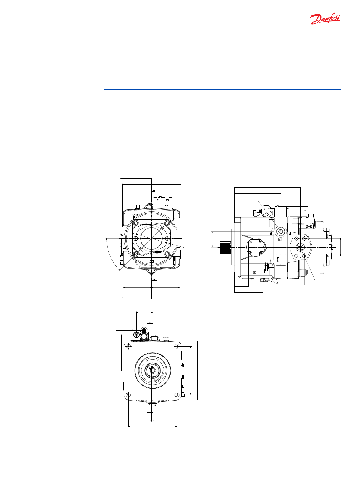
D1P 260 angle sensor
Angle sensor principle
The angle sensor option is exclusive to the D1P 260.
The angle sensor option offered in D1P allows users to measure the angle of pump displacement. The
angle sensor is an electronic sensor mounted to the housing of the pump, which reads the pump stroke
angle based on the swashplate position. Interfacing with the angle sensor is achieved through a 4-pin
DEUTSCH DTM04-4P receptacle attached to a flexible connection cable (for a mating connector, use
DEUTSCH plug DTM06-4S). The sensor is mounted to the pump within an aluminum housing to prevent
magnetic interference.
Location
When the input shaft with the control is on the top side, the angle sensor will be viewed on the righthand side. This convention is true for both clockwise and counterclockwise rotation.
©
Danfoss | December 2021 BC157786485289en-000501 | 11
Page 12
Technical Information
D1 High Power Open Circuit Pumps Size 130/145/193/260
Technical Specifications
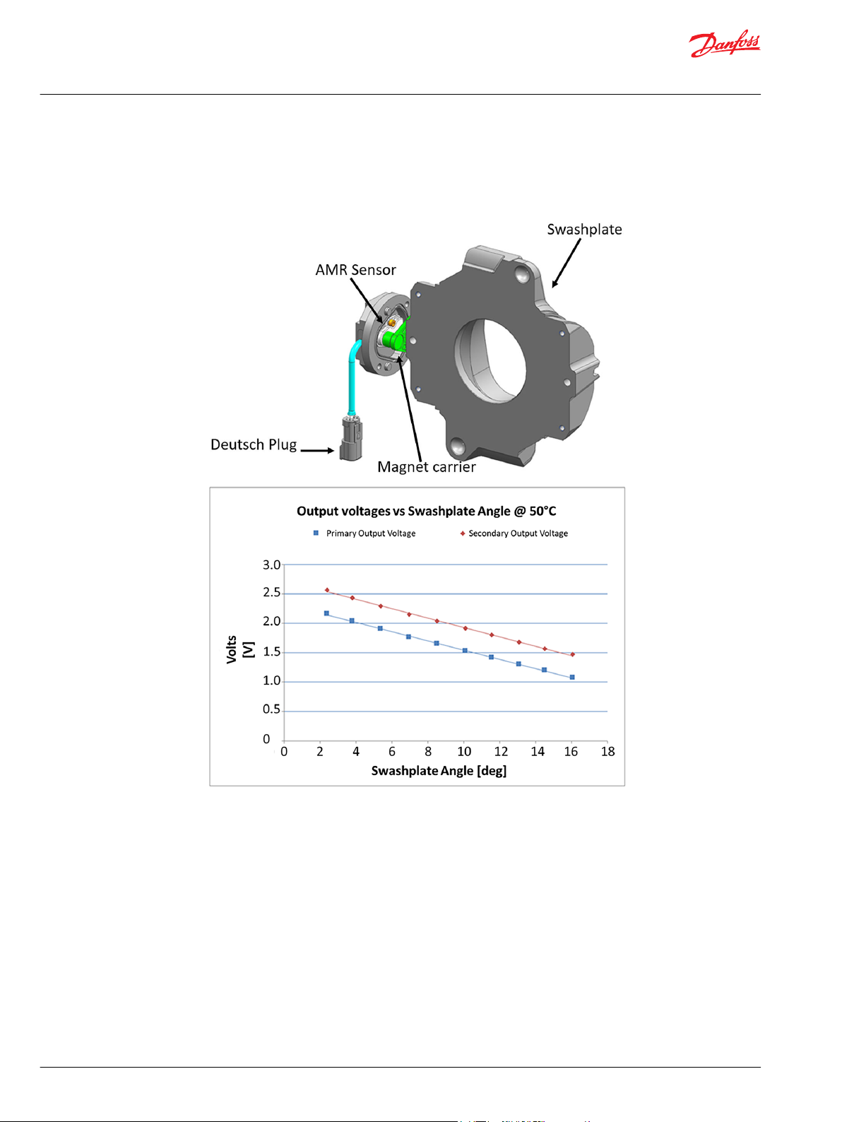
Angle sensor characteristics
The angle sensor package incorporates two sensor signals (primary & secondary) within a single sensor
housing. This package allows for improved accuracy and troubleshooting.
12 | © Danfoss | December 2021 BC157786485289en-000501
Page 13
Technical Information
D1 High Power Open Circuit Pumps Size 130/145/193/260
Technical Specifications
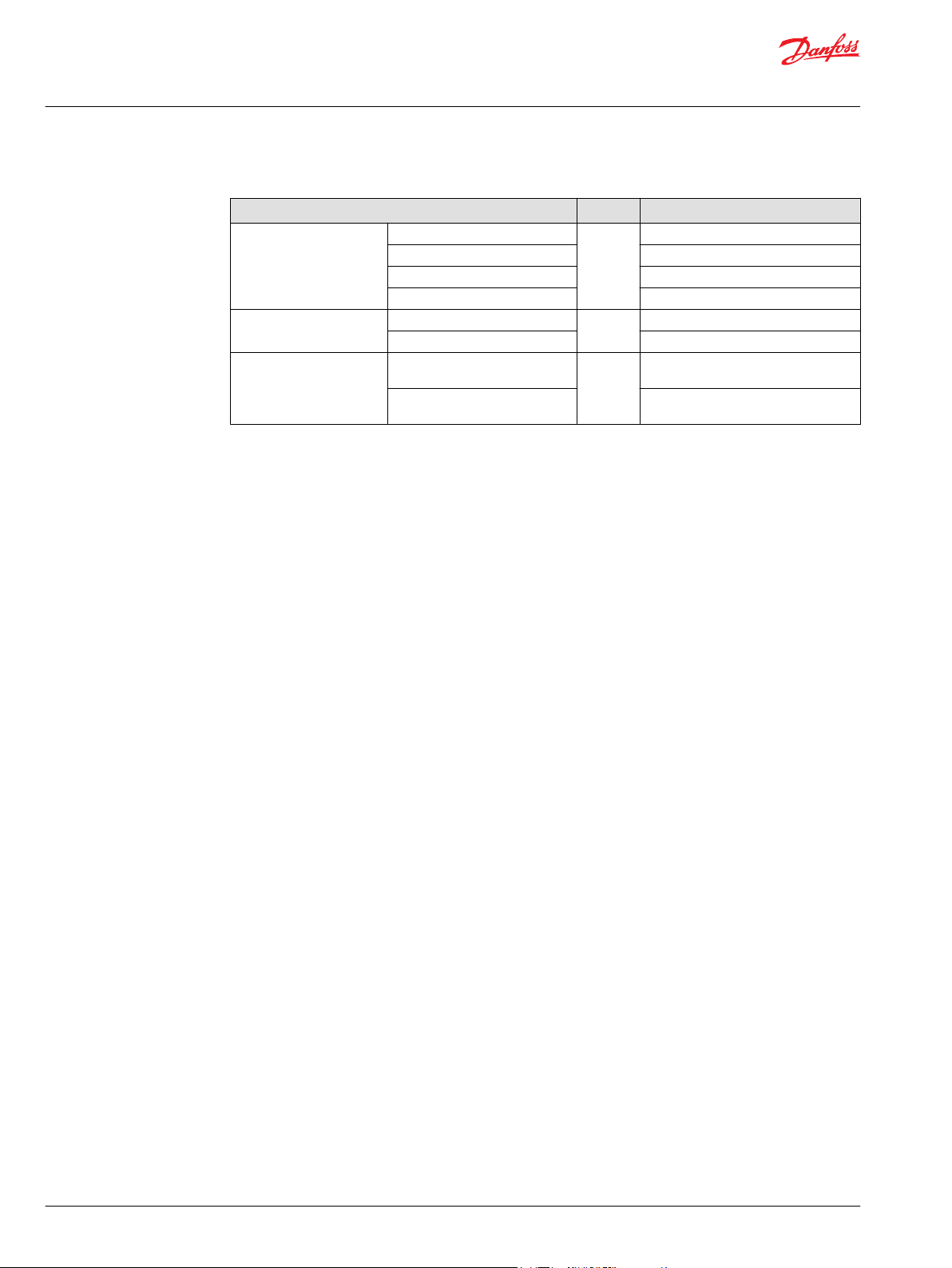
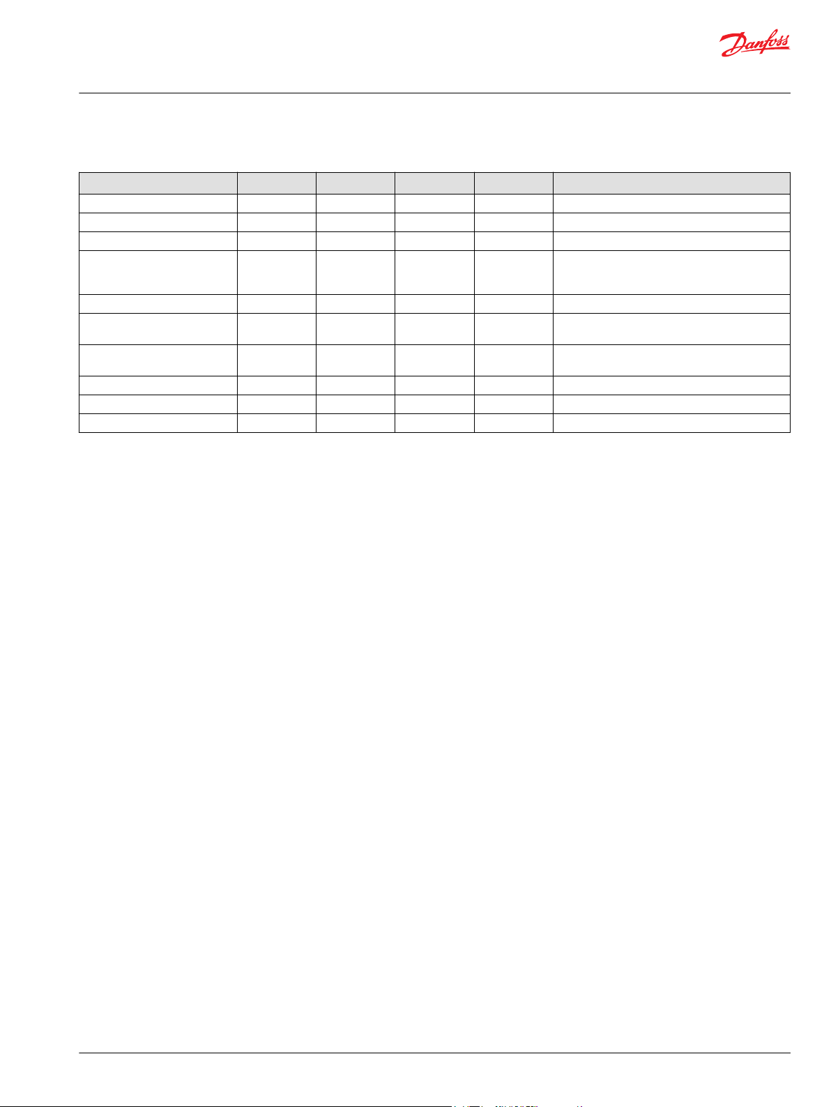
Angle sensor electrical specifications
Description Minimum Typical Maximum Unit Note
Supply (V+) 4.75 5 5.25 Vdc Sensor is ratiometric in the voltage range
Supply protection - - 28 Vdc Sensor will switch off above 5.5 V
Supply current drawn - 22 25 mA Sensor supply at 5 V
Output short circuit current
(VDD to SIG ½ and GND to SIG
½)
Resolution - 0.03 - Degree 11 bit output channel
Hysteresis - - - - Design of sensor eliminates any mechanical
Environment temperature
range
Operating temperature range 20 [68] 50 [122] 104 [220] °C [°F] Temperature of oil
Storage temperature -40 [-40] - 125 [257] °C [°F] Refresh rate of the sensor - - 100 µs Internal ADC refresh rate
- - 7.5 mA Additional 7.5 mA for each sensor signal, total
sensor 7.5x2+22=37 mA typical for FSO
hysteresis
-40 [-40] 80 [176] 104 [220] °C [°F] If temperature limits are exceeded, the sensor
will function at a reduced level of performance
Angle sensor calibration
A 2-point calibration of the sensor is recommended, with points measured at pump standby and
maximum pump stroke. Maximum pump stroke can be achieved when the pump input shaft is not being
turned, as D1P pumps are biased to maximum displacement. In some cases, the pump may need to be
turned momentarily to ensure the pump is in the maximum displacement position; this can be achieved
through a momentary switching of the engine starter on/off.
For minimum displacement calibration, the angle sensor can be calibrated by sending the pump to a
standby condition, either high-pressure with a pressure compensator (PC control) or low-pressure with a
flow compensator (LS control). Low-pressure standby is recommended if the control has load sensing or
remote PC functionality. For best results, it is recommended to rotate the prime mover at the highest
operating speed to achieve the lowest angle possible at standby conditions.
©
Danfoss | December 2021 BC157786485289en-000501 | 13
Page 14

Technical Information
D1 High Power Open Circuit Pumps Size 130/145/193/260
Technical Specifications
Angle sensor functionality
The D1P angle sensor option is intended for advanced functionality such as electronic torque limiting,
duty cycle measurement, troubleshooting, etc. The angle sensor is PLUS+1® compliant with an available
hardware compliance block.
Angle Sensor Intended Functionality:
•
Electronic Torque Limiting
•
Duty Cycle Recording
•
Troubleshooting
Angle Sensor Unsupported Functionality:
•
Displacement/Flow Control
*
*
Pre-programmed Electronic Torque Limiting control packages are currently not offered for D1P.
14 | © Danfoss | December 2021 BC157786485289en-000501
Page 15
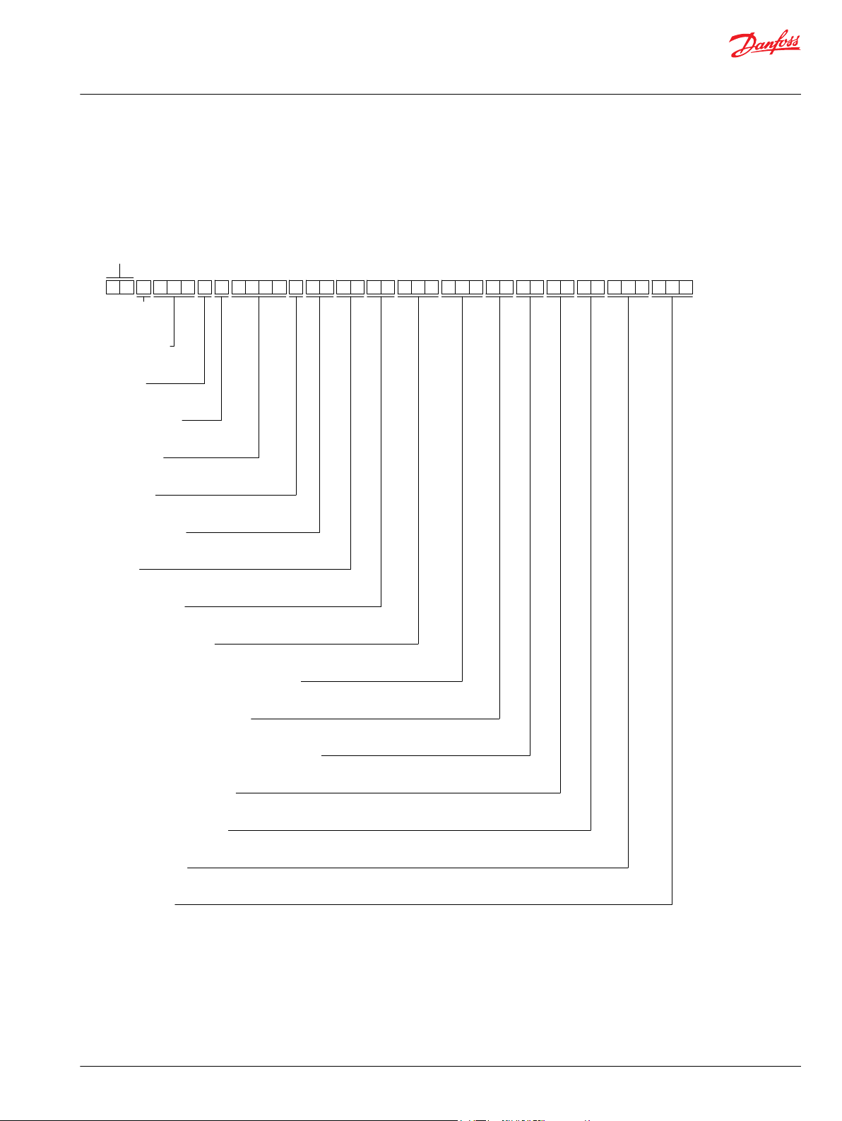
D 1 P 2 6 0 R A T P E 2 T E 4 Y 3 B 1 1 1 5 3 4 0 N N N N F S 0 5 N N N NN N
Series
Product
type
Displacement
A B C D E F G H J K L M N P R S
Rotation
Product version
Control type
Input shaft
Endcap
Power control setting
Pressure compensated control setting
Load sensing control setting
Hydraulic disp control start pressure setting
Max displacement setting
Min displacement setting
Special hardware
Special feature
Mounting flange
Auxiliary flange
Technical Information
D1 High Power Open Circuit Pumps Size 130/145/193/260
Model Code
D1P model code
The below illustration and the following sections describe how to identify parts of the model code and
availability of certain part options based on frame size.
Example model code; D1P 260 shown
©
Danfoss | December 2021 BC157786485289en-000501 | 15
Page 16
W
Technical Information
D1 High Power Open Circuit Pumps Size 130/145/193/260
Model Code
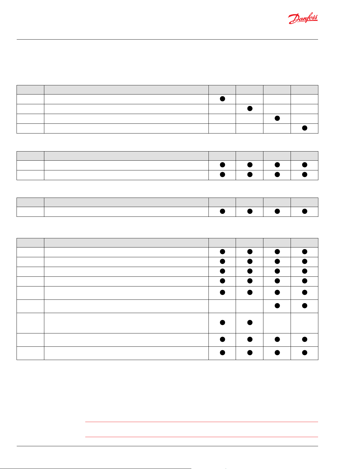
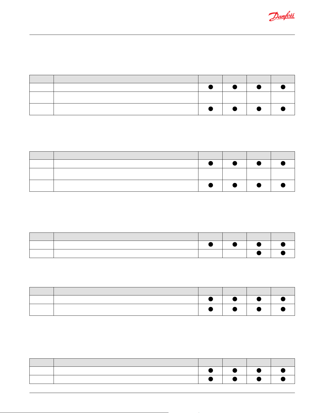
D1P 130-260 displacement, rotation and product version
Displacement
Code Description 130 145 193 260
130 130 cm3 [7.93 in3] max. displacement per revolution
145 145 cm3 [8.85 in3] max. displacement per revolution
193 193 cm3 [11.78 in3] max. displacement per revolution
260 260 cm3 [15.87 in3] max. displacement per revolution
Rotation
Code Description 130 145 193 260
R Clockwise [CW]
L Counter Clockwise [CCW]
Product Version
Code Description 130 145 193 260
A
D1P 130-260 control types
Code Description 130 145 193 260
NPNN Pressure Compensated Control
NPSN Pressure Compensated Control + Load Sensing Control
NPNR Pressure Compensated Control + Remote Pressure Compensated Control
TPSN Power Control + Pressure Compensated Control + Load Sensing Control
NNES Positive Electric Displacement Control (24V DEUTSCH, 2-pin) w/Manual Override +
TPE2 Power Control + Pressure Compensated Control + Positive Electric Displacement
TPE5
NPE2 Pressure Compensated Control + Positive Electric Displacement Control (24V
NPE0 Pressure Compensated Control + Positive Electric Displacement Control (24V
Load Sensing Control
Control (24V DEUTSCH, 2-pin) w/Manual Override
Power Control + Pressure Compensated Control + Positive Electric Displacement
Control (24V DEUTSCH, 2-pin) w/Manual Override
(The control outline and size is the same as the 193/260 TPE2 control)
DEUTSCH, 2-pin) w/Manual Override
DEUTSCH, 2-pin) w/Manual Override w/o Shuttle valve
Control Code Explanation:
•
First digit: Power control (Torque control) , "N" means no power control.
•
Second digit: Pressure compensated control, "N" means no pressure compensated control.
•
Third & Fourth digits: Proportional displacement control or Load sensing control , "NN" means no
control in either category.
Warning
A relief valve is required to be installed in the pump outlet for additional system protection. Failure to
install the relief valve can lead to system damage and/or injury.
16 | © Danfoss | December 2021 BC157786485289en-000501
Page 17
Technical Information
D1 High Power Open Circuit Pumps Size 130/145/193/260
Model Code
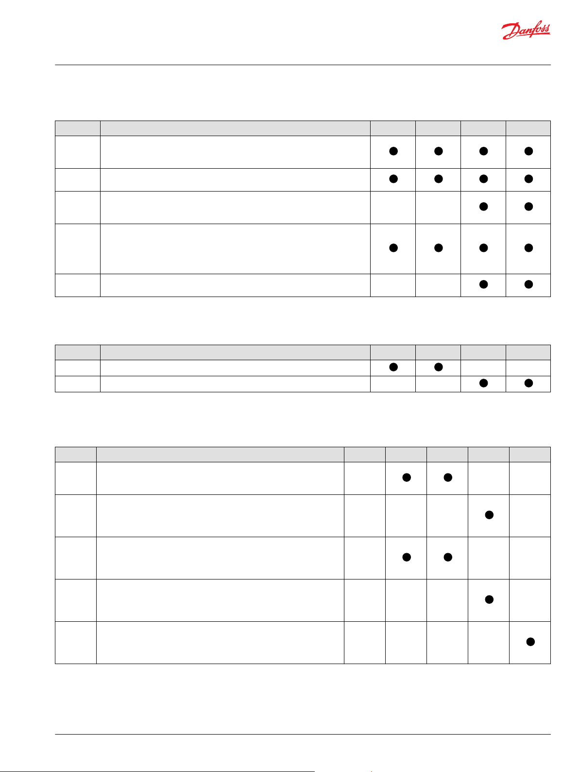
D1P 130-260 input shaft options
Code Description 130 145 193 260
T 130/145/193: Spline, DIN 5480 W50 x 2 x 30 x 24 x 9g;
260: Spline, DIN 5480 W60 x 2 x 30 x 28 x 9g;
Shaft Seal Material: FKM
S Spline, SAE J744 1 3/4in, 13T 8/16 DP;
Shaft Seal Material: FKM
A 193: Spline, SAE J744 2in, 15T 8/16 DP;
260: Spline, SAE J744 2 1/4in, 17T 8/16 DP;
Shaft Seal Material: FKM
P Straight Keyed DIN 6885,
130/145: AS14 x 9 x 80
193: AS16 x 10 x 100
260: AS18 x 11 x 100
Shaft Seal Material: FKM
*
K
SAE J744 (D/E) 3in straight keyed shaft
0.4375x3.000in
*
There is no impeller option for sizes 130 and 145 with this shaft.
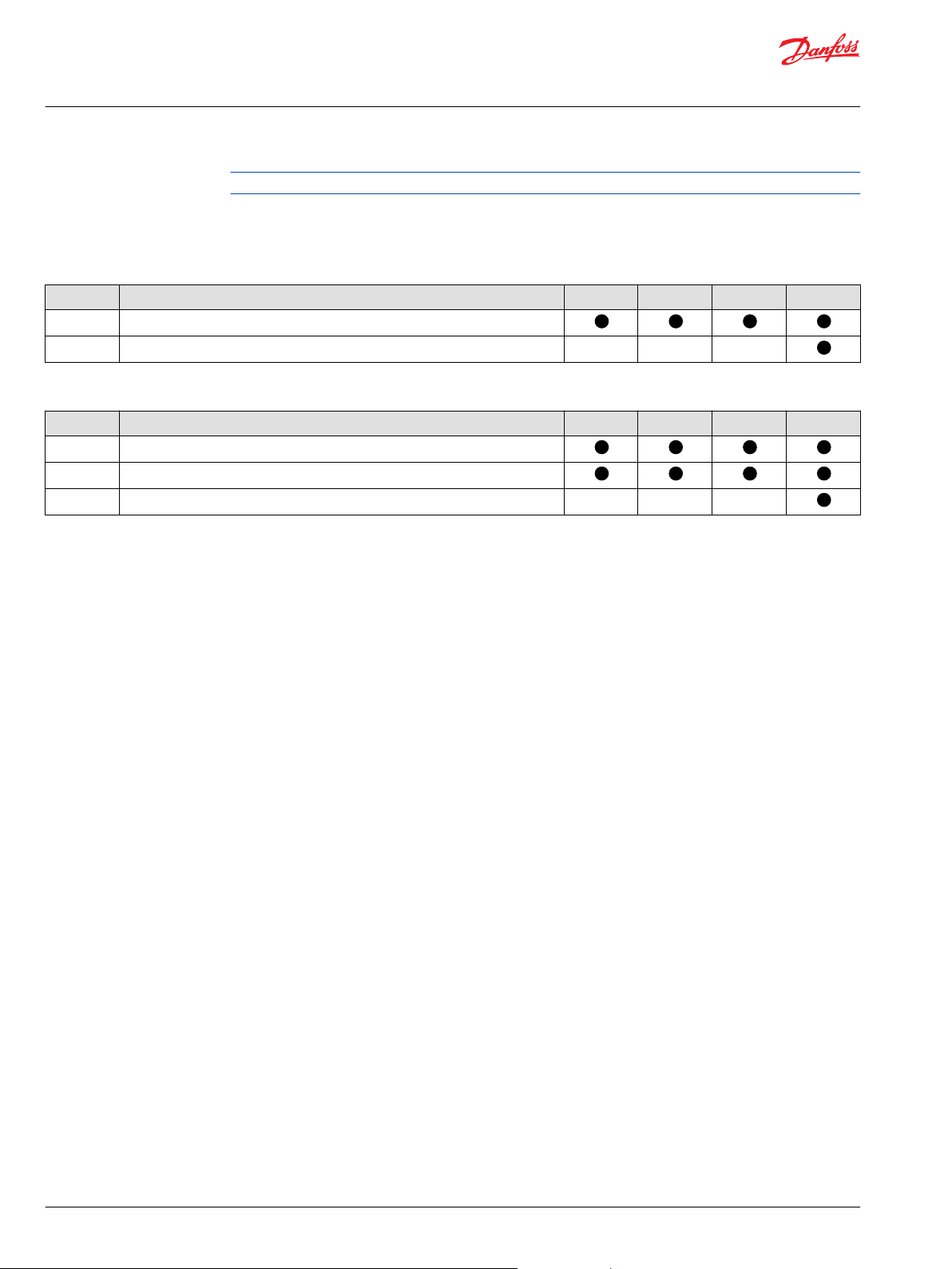
D1P 130-260 mounting flange options
Code Description 130 145 193 260
D4 SAE J744 152-4 (D)
E4 SAE J744 165-4 (E)
D1P 130-260 end cap and main port options
End cap and main ports
Code Description Rotation 130 145 193 260
N1 Radial, side, flange ports
Inlet: 3in port, M16 x 2;
Outlet: 1in port, M12 x 1.75 SAE J518 without impeller
N2 Radial, side, flange ports
Inlet: 3 1/2in, M16 x 12;
Outlet: 1 1/2in, M16 x 2 SAE J518
Without impeller
Y1 Radial, side, flange ports
Inlet: 3in port, M16 x 2;
Outlet: 1 1/4in port, M14 x 2 SAE J518
With impeller
Y2 Radial, side, flange ports
Inlet: 3 1/2in port, M16 x 2;
Outlet: 1 1/2in port, M16 x 2 SAE J518
With impeller
Y3 Radial, side, flange ports
Inlet: 4in port, M16 x 2;
Outlet: 1 1/2in port, M16 x 2 SAE J518
With impeller
CW [R]
CCW [L]
CW [R]
CW [R]
CCW [L]
CW [R]
CCW [L]
CW [R]
CCW [L]
©
Danfoss | December 2021 BC157786485289en-000501 | 17
Page 18
P
setting@1500 rpm
= P
actual *
n
actual
1500
Technical Information
D1 High Power Open Circuit Pumps Size 130/145/193/260
Model Code
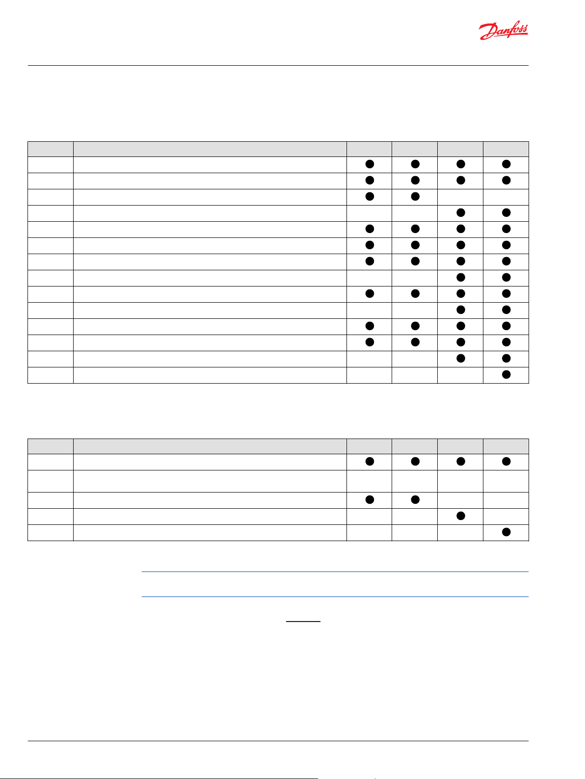
D1P 130-260 auxiliary mounting flange options
Auxiliary mounting flange (through-drive flange)
Code Description 130 145 193 260
NN No auxiliary flange
A1 SAE J744 82-2 (A); Spline coupling: 5/8in 9T 16/32DP
A2 SAE J744 82-2 (A); Spline coupling: 3/4in 11T 16/32DP
A3 SAE J744 82-2 (A); Spline coupling: 7/8in 13T 16/32DP
B1 SAE J744 101-2 (B) ; Spline coupling: 7/8in 13T 16/32DP
B2 SAE J744 101-2 (B); Spline coupling: 1in 15T 16/32DP
BA SAE J744 101-2 (B); Spline coupling: 7/8in 13T 16/32DP; Adapter 90°
BB SAE J744 101-2 (B); Spline coupling: 7/8in 13T 16/32DP; Cover 45°
C5 SAE J744 127-2&4 (C) ; Spline coupling:1 1/4in 14T 12/24DP
C9 SAE J744 127-2&4 (C); Spline coupling: 1 3/4in 13T 8/16DP
D2 SAE J744 152-4 (D); Spline coupling: 1 3/4in 13T 8/16DP
D5 SAE J744 152-4 (D) ; Spline coupling: N50x2x30x24x9H
E2 SAE J744 165-4 (E) ; Spline coupling: N50 x 2 x 30 x 24 x 9H
E3 SAE J744 165-4 (E) ; Spline coupling: N60 x 2 x 30 x 28 x 9H
D1P 130-260 power control settings
Power control setting at 1500rpm (kW), “3 digit code”
1
Code
NNN No Power Control
XXX xxx kW between ranges specified below (For example: Code "090" means 90kW)
030-115 30-115 kW [40-154 hp] at 1500 rpm
035-155 35-155 kW [47-208 hp] at 1500 rpm
040-210 40-210 kW [54-282 hp] at 1500 rpm
1
For settings out of these ranges, please contact Danfoss Power Solutions.
2
Only increments of 5kW [6.7 hp] are allowed. E.g. 035, 040, 045, etc.)
Description 130 145 193 260
at 1500 rpm
2
2
2
If the speed is not 1500rpm, please make a conversion using the following formula, assuming constant
torque:
For example:
If actual power is 110 kW at 2100 rpm, the conversion to obtain the power control setting at 1500 rpm
should be 110*1500/2100=79, choose 080 option (round to closest 5 kW increment option).
18 | © Danfoss | December 2021 BC157786485289en-000501
Page 19
Technical Information
D1 High Power Open Circuit Pumps Size 130/145/193/260
Model Code
D1P 130-260 pressure compensated control setting
Pressure compensated control setting (bar), “3 digit code”
*
Code
NNN No Pressure compensated control
XXX xxx bar between the range specified below (For example: Code "320" means 320
150~350 150~350 bar [2176~5076 psi] (Please select pressure compensated control setting
*
For settings out of these ranges, please contact Danfoss Power Solutions.
D1P 130-260 load sensing control settings
L - Load Sensing Control Setting (bar), "2 digit code"
Code Description 130 145 193 260
NN No load sensing control
XX xx bar between the range specified below (For example: Code "25" means 25 bar
10~35*10~35 bar [145~508 psi] (Please select load sensing control setting in increments
*
For settings out of these ranges, please contact Danfoss Power Solutions. Range allowed for NPNR (Pressure compensated + Remote Pressure
compensated control) is 15-35 bar
Description 130 145 193 260
bar [4641 psi])
in increments of 10 bar [145 psi]. E.g. 150 or 160 or 170, etc.)
[363 psi])
of 1 bar [14.5 psi]. E.g. 10 or 11 or 12, etc.)
D1P 130-260 hydraulic displacement control setting
Hydraulic displacement control start pressure setting, “2 digit code”
Code Description 130 145 193 260
NN No hydraulic displacement control
04-10 4-10 bar
D1P 130-260 maximum displacement settings
Maximum displacement setting, “2 digit code”
Code Description 130 145 193 260
FS Factory setting : 100%
1
XX
1
Please consider frame sizing and increments when selecting a maximum displacement setting (see displacement limiter for more information).
2
Only increments of 5% are allowed. (E.g. 70, 75, 80 etc.)
XX% of maximum displacement (For example: Code "90" means 90% of maximum
displacement)
2
D1P 130-260 minimum displacement settings
Minimum displacement setting, “2 digit code”
Code Description 130 145 193 260
FS 0% of maximum displacement limit setting
XX XX% of maximum displacement limit setting
1
Only increments of 5% are allowed. (E.g. 05, 10, etc.)
1
©
Danfoss | December 2021 BC157786485289en-000501 | 19
Page 20
Technical Information
D1 High Power Open Circuit Pumps Size 130/145/193/260
Model Code
If a different minimum displacement setting is required, please contact Danfoss Power Solutions.
D1P 130-260 special hardware and special features
Special hardware
Code Description 130 145 193 260
NNN None
NNA No special hardware; with angle sensor
Special features
Code Description 130 145 193 260
NNN Factory Setting (Paint-black, tag, Danfoss, format A)
NXN Factory Setting (No paint, tag, Danfoss, format A, w/o filter)
NNF Factory Setting (Paint-black, tag , Danfoss, format A) with control oil filter
20 | © Danfoss | December 2021 BC157786485289en-000501
Page 21
P400282
Control
Pump
Endcap
Control
Pump
Endcap
P400282
Control
Pump
Endcap
Control
Pump
Endcap
Control
Pump
Endcap
Technical Information
D1 High Power Open Circuit Pumps Size 130/145/193/260
Model Code
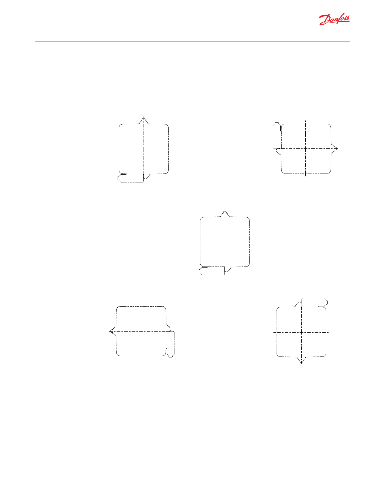
D1P tandem pump information
Information about tandem pump direction and ordering instructions are found below.
Pump direction
Auxiliary pump
INDEX = 0°
Auxiliary pump
INDEX = 90°
When assembling a system the first
pump is always to be considered at 0°
INDEX as shown below.
Auxiliary pump
INDEX = 270°
Auxiliary pump
INDEX = 180°
For gear pump tandem angle information, please contact Danfoss Power Solutions.
Ordering tandem pumps
When ordering tandem pumps, the type designations of the 1st and 2nd pumps must be connected by a
“+”, and tandem pump angle should be given as indicated below.
Ordering example:
D1P193RATPE2TE4Y2E2090320NNNNFSFSNNNNNN +
D1P193RATPE2TE4Y2NN090320NNNNFSFSNNNNNN
Tandem angle 0° + 180°
©
Danfoss | December 2021 BC157786485289en-000501 | 21
Page 22
0.8
0.9
Speed
n
max
/
n
max1
0.9
1.0
Displacement Vg/Vgmax
1.0
1.1
1.2
Pabs=1 bar [14.5 psi]
Pabs=1.5 bar [21.8 psi]
P400076
Technical Information
D1 High Power Open Circuit Pumps Size 130/145/193/260
Parameters
D1P pressure overview
D1P speed overview
Maximum
working
pressure
The highest recommended outlet (application). Operating at or below this pressure
should yield satisfactory product life. For all applications, the load should move below
this pressure. This corresponds to the maximum allowable pressure compensated
control setting.
Maximum
(peak) pressure
The highest intermittent (t<1s) outlet pressure allowed. Maximum machine load
should never exceed this pressure, and pressure overshoots should not exceed this
pressure.
Inlet pressure The absolute pressure in the pump suction port, it is related to pump speed. Make
sure it is in the allowable range, see D1 pump specifications.
Case pressure The case pressure at the ports L1 and L2 may be a maximum of 1.2 bar [17.4 psi]
higher than the inlet pressure at the port S but not higher than 2 bar. Size drain
plumbing accordingly and connect it to tank directly. The housing must always be
filled with hydraulic fluid.
Rated
speed
The fastest recommended operating speed at full displacement and at least 0.6 bar [8.7
psi] abs with charge pump (0.8 bar [11.6 psi] abs without charge pump) inlet pressure.
Operating at or below this speed should yield satisfactory product life.
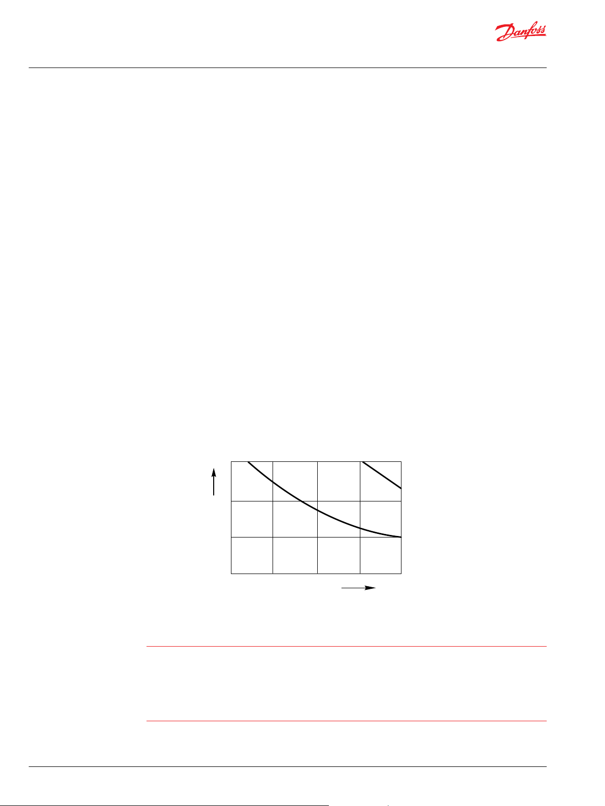
Maximum
speed
The highest recommended operating speed at full power conditions. Operating at or
beyond maximum speed requires positive inlet pressure and/or a reduction of pump
outlet flow. Refer to the Inlet pressure vs. speed chart below.
Inlet pressure vs. speed
Minimum
speed
The lowest operating speed allowed. Operating below this speed will not yield
satisfactory performance.
Caution! Threat to pump life!
Working outside of the pump's operating parameters may result in shortened life expectancy of the
pump.
22 | © Danfoss | December 2021 BC157786485289en-000501
Always work within the operating conditions of the pump application.
With accurate duty cycle information, your Danfoss Power Solutions representative can assist you in
calculating expected pump life.
Page 23
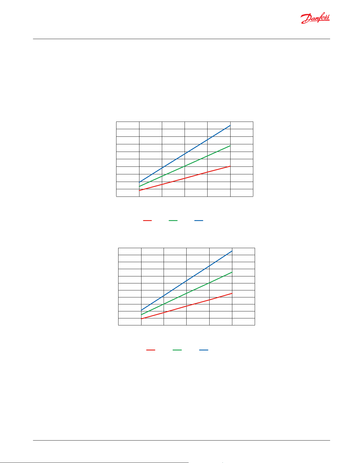
200
180
160
140
Power [kW]
120
100
80
60
40
20
0
0 500 1000
Speed [rpm]
1500 2000 2500 3000
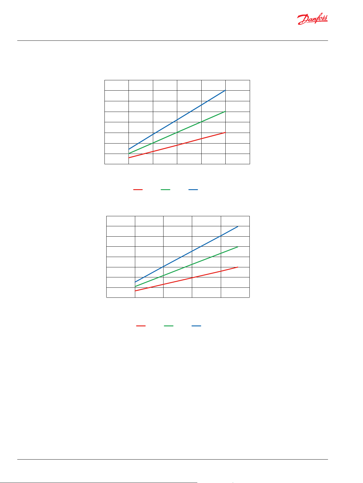
150 bar 250 bar 350 bar
200
180
160
140
Power [kW]
120
100
80
60
40
20
0
220
0 500 1000
Speed [rpm]
1500 2000 2500 3000
150 bar 250 bar 350 bar
Technical Information
D1 High Power Open Circuit Pumps Size 130/145/193/260
Parameters
Performance
D1P input power
Input power requirements depend on displacement per revolution, speed, efficiency, and operating
pressure.
130cc power vs input speed
©
Danfoss | December 2021 BC157786485289en-000501 | 23
145cc power vs input speed
Page 24
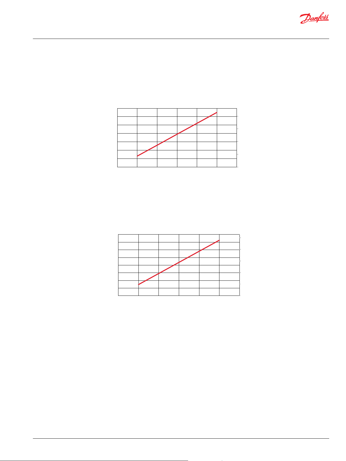
0 500 1000
Speed [rpm]
1500 2000 2500 3000
150 bar 250 bar 350 bar
Power [kW]
0
40
80
120
160
200
240
280
320
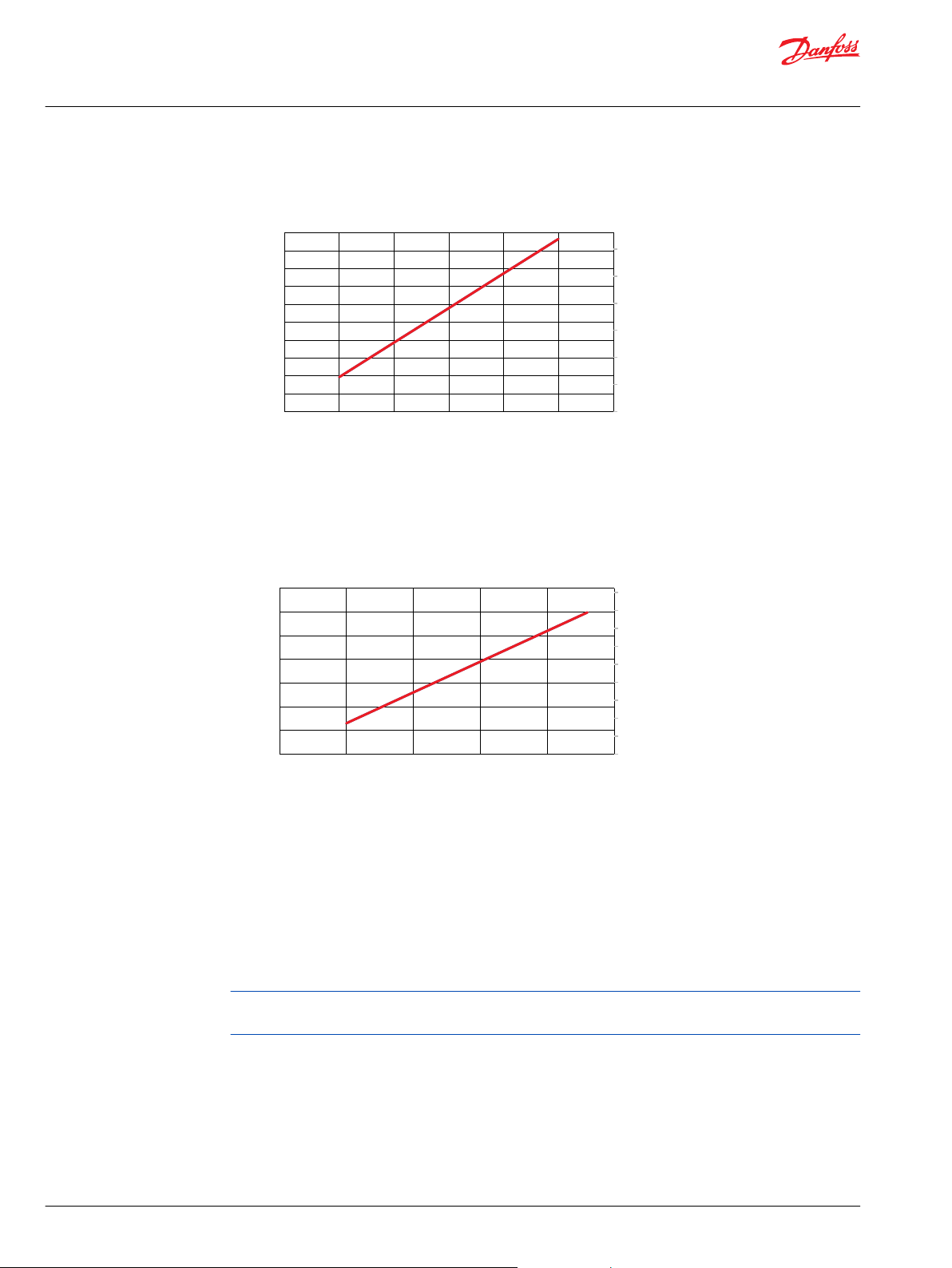
0 500 1000
Speed [rpm]
1500 2000 2500
150 bar 250 bar 350 bar
Power [kW]
0
50
100
150
200
250
300
350
400
Technical Information
D1 High Power Open Circuit Pumps Size 130/145/193/260
Parameters
193cc power vs input speed
260cc power vs input speed
24 | © Danfoss | December 2021 BC157786485289en-000501
Page 25
0
20
40
60
80
0
50
100
150
200
250
300
350
0 500 1000 1500 2000 2500 3000
Flow [US gal/min]
Flow [l/min]
Speed [rpm]
0
20
40
60
80
100
0
50
100
150
200
250
300
350
400
0 500 1000 1500 2000 2500 3000
Flow [US gal/min]
Flow [l/min]
Speed [rpm]
Technical Information
D1 High Power Open Circuit Pumps Size 130/145/193/260
Parameters
D1P output flow
Output flow depends on displacement per revolution, speed, and efficiency.
130cc flow vs speed
145cc flow vs speed
©
Danfoss | December 2021 BC157786485289en-000501 | 25
Page 26
0
20
40
60
80
100
120
0
50
100
150
200
250
300
350
400
450
500
0 500 1000 1500 2000 2500 3000
Flow [US gal/min]
Flow [l/min]
Speed [rpm]
0
20
40
60
80
100
120
140
160
180
0
100
200
300
400
500
600
700
0 500 1000 1500 2000 2500
Flow [US gal/min]
Flow [l/min]
Speed [rpm]
Technical Information
D1 High Power Open Circuit Pumps Size 130/145/193/260
Parameters
193cc flow vs speed
260cc flow vs speed
D1P efficiency overview
Efficiency data depends on various operating parameters such as: working and inlet pressure, operating
temperature, displacement, and fluid viscosity. For an accurate efficiency calculation, please contact your
Danfoss Power Solutions representative.
All performance data are theoretical values, without efficiency or tolerances. Data valid at full
displacement and operation parameters within the recommended ranges.
26 | © Danfoss | December 2021 BC157786485289en-000501
Page 27
Technical Information
D1 High Power Open Circuit Pumps Size 130/145/193/260
Parameters
D1P fluid overview
Ratings and performance data for D1 pumps are based on operating with premium hydraulic fluids
containing oxidation, rust, and foam inhibitors. These include premium turbine oils, API CD engine oils
per SAE J183, M2C33F or G automatic transmission fluids (ATF), Dexron II (ATF) meeting Allison C-3 or
Caterpillar T0‑2 requirements, and certain specialty agricultural tractor fluids. For more information on
hydraulic fluid selection, see Danfoss Power Solutions publications BC152886484524 Hydraulic Fluids
and Lubricants, Technical Information, and 520L0465 Experience with Biodegradable Hydraulic Fluids,
Technical Information.
D1P viscosity
Minimum Viscosity This should only occur during brief occasions of maximum ambient temperature
and severe duty cycle operation.
Maximum
Viscosity
This should only occur at cold start. Pump performance will be reduced. Limit
speeds until the system warms up.
Maintain fluid viscosity within the recommended range for maximum efficiency and pump life.
D1P temperature overview
Minimum
Temperature
Relates to the physical properties of the component materials. Cold oil will not
affect the durability of the pump components. However, it may affect the ability of
the pump to provide flow and transmit power
Maximum
Temperature
Relates to material properties. Don’t exceed it. Measure maximum temperature at
the hottest point in the system. This is usually the case drain.
D1P fluid velocity
Choose piping sizes and configurations sufficient to maintain optimum fluid velocity, and minimize
pressure drops. This reduces noise, pressure drops, overheating and maximizes system life and
performance.
Recommended fluid velocities
System lines
Suction line
Case drain
6 to 9 m/sec
1 to 2 m/sec
3 to 5 m/sec
Typical guidelines; obey all pressure ratings.
Velocity equations
SI units
Q = flow (l/min)
A = area (mm²)
Velocity = (16.67•Q)/A (m/sec)
©
Danfoss | December 2021 BC157786485289en-000501 | 27
Page 28
Technical Information
D1 High Power Open Circuit Pumps Size 130/145/193/260
Parameters
D1P shaft torque ratings
Shaft drawings and maximum torque ratings are found in these sections:
•
Size 130/145 shaft specifications
•
Size 193 shaft specifications
•
Size 260 shaft specifications
Maximum torque ratings are based on shaft strength with no radial force; do not exceed the torque
limits.
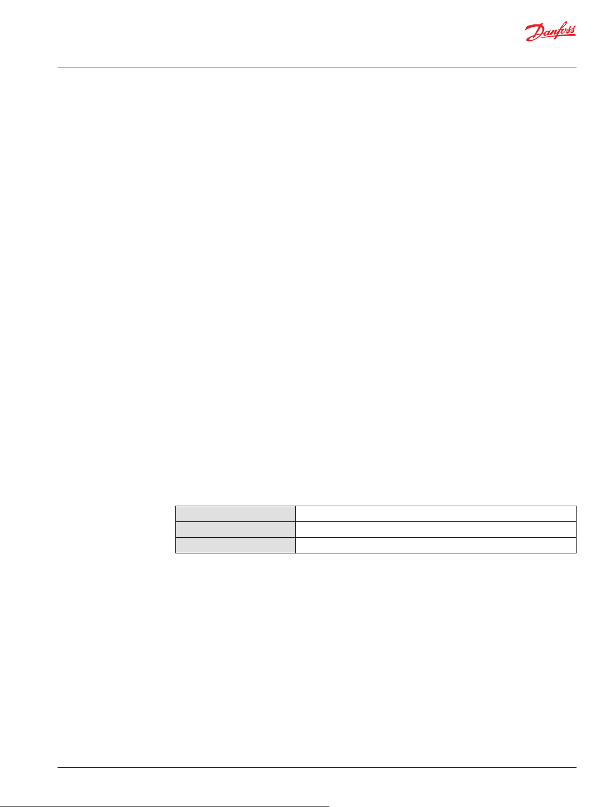
D1P shaft load
Series D1 pump bearing is capable of accepting external radial and thrust (axial) loads. The external radial
shaft load limits are a function of the load position, orientation, and the operating conditions of the
pump.
The maximum allowable radial load (Re) is based on the maximum external moment (Me) and the
distance (L) from the mounting flange to the load. Compute radial loads using the formula below. D1
pump specifications gives maximum external radial load (Re) and thrust (axial) load (Tin , T
) limits .
out
D1P mounting flange loads
Me = Re • L L = Distance from mounting flange to point of load
All shaft loads affect bearing life. In applications where external shaft loads cannot be avoided, maximize
bearing life by orienting the load between the 150° and 210° positions, as shown.
Adding auxiliary pumps and/or subjecting pumps to high shock loads may overload the pump mounting
flange. D1 pump specifications gives allowable continuous and shock load moments. Applications with
loads outside allowable limits require additional pump support.
Shock load moment (MS) is the result of an instantaneous jolt to the system.
•
Continuous load moments (MC) are generated by the typical vibratory movement of the application.
•
Me = Maximum external moment
Re = Maximum radial side load
D1P auxiliary mounting pads
Auxiliary mounting pads are available. Since the auxiliary pad operates under case pressure, use an Oring to seal the auxiliary pump mounting flange to the pad. Oil from the main pump case lubricates the
drive coupling.
28 | © Danfoss | December 2021 BC157786485289en-000501
Page 29
P400078
L1
L2
1
2 3
Technical Information
D1 High Power Open Circuit Pumps Size 130/145/193/260
Parameters
The combination of auxiliary shaft torque and main pump torque must not exceed the maximum
•
pump input shaft rating. Shaft drawing section in Installation drawings chapter gives input shaft
torque ratings.
Applications subject to severe vibratory or shock loading may require additional support to prevent
•
mounting flange damage. The table gives allowable continuous and shock load moments.
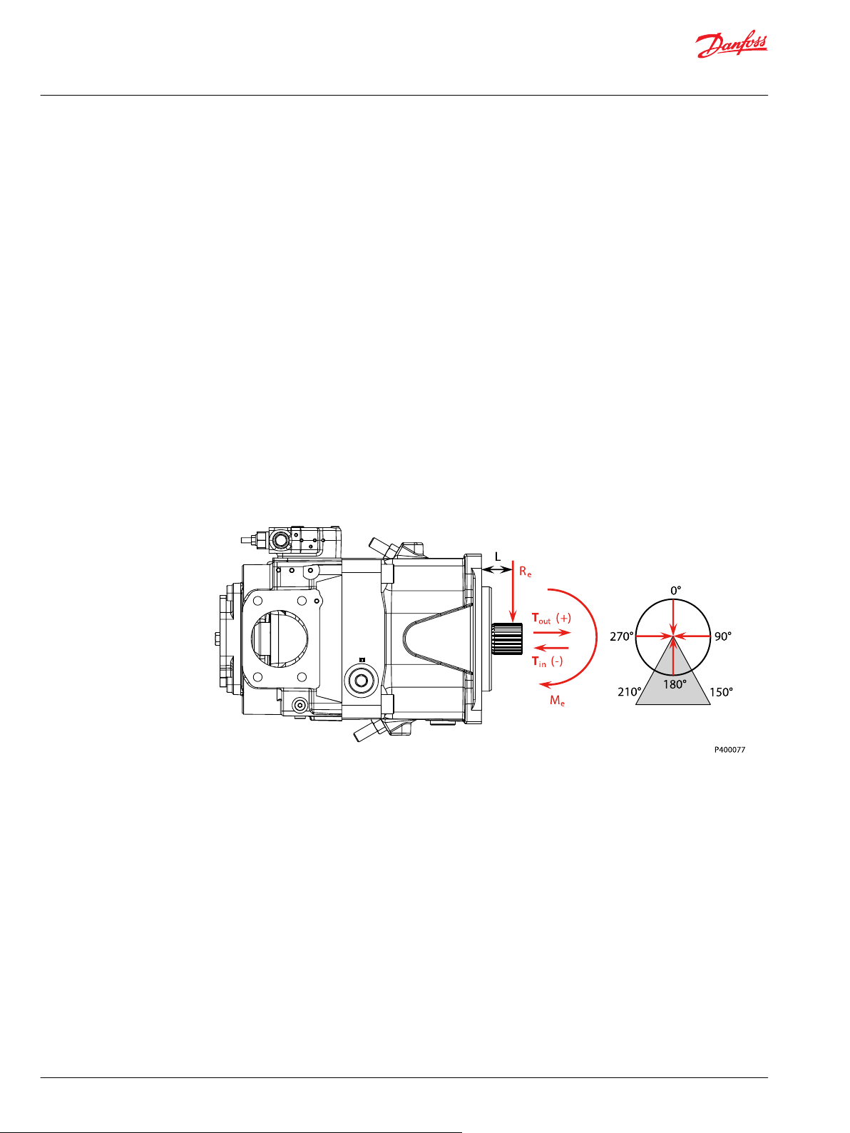
D1P estimating overhung load moments
Use the equations below to estimate the overhung load moments for multiple pump mounting. See
Installation drawings chapter to find the distance from the mounting flange to the center of gravity. Refer
to the to find pump weight.
Overhung load example
1. Mounting Flange 2. Center of Gravity (CG), Pump 1 3. Center of Gravity (CG), Pump 2
Shock load formula MS = GS•K•(W1•L1+W2•L2+...Wn•Ln)
•
Continuous load formula MC = GC•K•(W1•L1+W2•L2+...Wn•Ln)
•
SI units
MS = Shock load moment (N•m)
MC = Continuous (vibratory) load moment (N•m)
GS = Acceleration due to external shock (G’s)
GC = Acceleration due to continuous vibration (G’s)
K = Conversion factor = 0.00981
Wn = Mass of nth pump (kg)
Ln = Distance from mounting flange to nth pump CG (mm)
©
Danfoss | December 2021 BC157786485289en-000501 | 29
Page 30

Technical Information
D1 High Power Open Circuit Pumps Size 130/145/193/260
Parameters
Understanding and minimizing system noise
Noise is transmitted in fluid power systems in two ways: as fluid borne noise, and structure borne noise.
Fluid-borne noise (pressure ripple or pulsation) is created as pumping elements discharge oil into the
pump outlet. It is affected by the compressibility of the oil, and the pump’s ability to transition pumping
elements from high to low pressure. Pulsations travel through the hydraulic lines at the speed of sound
until there is a change (such as an elbow) in the line. Amplitude varies with overall line length and
position.
Structure borne noise is transmitted wherever the pump casing connects to the rest of the system. The
way system components respond to excitation depends on their size, form, material, and mounting.
System lines and pump mounting can amplify pump noise.
Follow these suggestions to help minimize noise in your application:
Use flexible hoses.
•
Limit system line length.
•
If possible, optimize system line position to minimize noise.
•
If you must use steel plumbing, clamp the lines.
•
If you add additional support, use rubber mounts.
•
Test for resonance in the operating range; if possible avoid them.
•
D1P installation
D1P filtration
Series D1 pumps may be installed in any position. To optimize inlet conditions, install the pump at an
elevation below the minimum reservoir fluid level. Design inlet plumbing to maintain inlet pressure
within prescribed limits (see Inlet pressure limits on D1 pump specifications)
Fill the pump housing and inlet line with clean fluid during installation. Connect the case drain line to the
uppermost drain port (L1, L2 or L3) to keep the housing full during operation.
To allow unrestricted flow to the reservoir, use a dedicated drain line. Connect it below the minimum
reservoir fluid level and as far away from the reservoir outlet as possible. Use plumbing adequate to
maintain case pressure within prescribed limits (see case pressure limits on D1 pump specifications).
To prevent damage to the pump, including premature wear, fluid entering the pump inlet must be free of
contaminants. Series D1 pumps require system filtration capable of maintaining fluid cleanliness at class
20/18/15 according to ISO 4406-1999 or better.
Danfoss Power Solutions does not recommend suction line filtration. Suction line filtration can cause high
inlet vacuum, which limits pump operating speed. Instead we recommend a 125 μm (150 mesh) screen in
the reservoir covering the pump inlet. This protects the pump from coarse particle ingestion.
Return line filtration is the preferred method for open circuit systems. Consider these factors when
selecting a system filter:
Cleanliness specifications
•
Contaminant ingression rates
•
Flow capacity
•
Desired maintenance interval
•
Typically, a filter with a beta ratio of β10 = 10 is adequate. However, because each system is unique, only
a thorough testing and evaluation program can fully validate the filtration system.
For more information, see Danfoss Power Solutions publication BC152886482150 Design Guidelines for
Hydraulic Fluid Cleanliness.
30 | © Danfoss | December 2021 BC157786485289en-000501
Page 31

Based on SI units
= (l/min)
Input torque M = (N•m)
Input power P = = (kW)
Based on US units
= (US gal/min)
Input torque M = (lbf•in)
Input power P = = (hp)
Vg • n • η
v
1000
Vg • ∆p
20 • π • η
m
Q • ∆p
600 • η
t
M • n • π
30 000
Vg • n • η
v
231
Vg • ∆p
2 • π • η
m
Q • ∆p
1714 • η
t
M • n • π
198 000
Flow
Torque
Power
Technical Information
D1 High Power Open Circuit Pumps Size 130/145/193/260
Parameters
Reservoir
The reservoir provides clean fluid, dissipates heat, and removes entrained air from the hydraulic fluid. It
allows for fluid volume changes associated with fluid expansion and cylinder differential volumes.
Minimum reservoir capacity depends on the volume needed to perform these functions. Typically, a
capacity of one to three times the pump flow (per minute) is satisfactory.
Locate the reservoir outlet (suction line) near the bottom, allowing clearance for settling foreign particles.
Place the reservoir inlet (return lines) below the lowest expected fluid level, as far away from the outlet as
possible.
Sizing Equations
Use these equations to help choose the right pump size and displacement for your application.
Variables
SI units [US units]
Vg= Displacement per revolution cm3/rev [in3/rev]
PO= Outlet pressure bar [psi]
Pi= Inlet pressure bar [psi]
∆p = pO - pi (system pressure) bar [psi]
n = Speed min-1 (rpm)
ηv= Volumetric efficiency
ηm= Mechanical efficiency
ηt= Overall efficiency (ηv • ηm)
©
Danfoss | December 2021 BC157786485289en-000501 | 31
Page 32

0
0
Q max
Flow
Pressure
W
Technical Information
D1 High Power Open Circuit Pumps Size 130/145/193/260
Control Type
NPNN (Pressure Compensated Control)
D1P 130/145/193/260+NPNN
Pressure Compensated Control (P) Principle
The P control design maintains a constant pressure in the hydraulic circuit as flow varies. The P control
modulates pump flow accordingly to maintain system pressure at the P setting as the P adjusting screw
and spring defines.
Pressure Compensated Control (P) Operation
When system pressure, acting on the non-spring end of the P spool, overcomes the force of the P spring,
the spool shifts porting system pressure to the servo piston and the swashplate angle decreases. When
system pressure drops below the P setting, the P spring shifts the spool in the opposite direction
connecting the servo piston to pump case and the swashplate angle increases. The swashplate is
maintained at whatever angle is required to keep system pressure at the P setting.
P characteristic
Warning
A relief valve is required to be installed in the pump outlet for additional system protection. Failure to
install the relief valve can lead to system damage and/or injury.
32 | © Danfoss | December 2021 BC157786485289en-000501
Page 33

Technical Information
D1 High Power Open Circuit Pumps Size 130/145/193/260
Control Type
Response/Recovery
Pressure Compensated (PC) Control Response/Recovery Times* @80°C, 350 bar, 1500rpm
Frame Size Response (msec) Recovery (msec)
130cc 150 270
145cc 150 270
1
193cc
260cc 154 327
1
Tested at 1800rpm
Values may vary depending on application conditions. For more information, please contact Danfoss
Power Solutions.
280 500
©
Danfoss | December 2021 BC157786485289en-000501 | 33
Page 34

Technical Information
D1 High Power Open Circuit Pumps Size 130/145/193/260
Control Type
NPSN (Pressure Compensated Control + Load Sensing Control)
D1P 130/145/193/260+NPSN
Pressure Compensated Control (P) Principle and Operation
Please refer to NPNN (Pressure Compensated Control) on page 32
Load Sensing Control (S) Principle
The S control design matches pump flow with system demand. The S control senses the flow demand of
the system as a pressure drop across the external control valve (1).
As (1) opens and closes, the pressure difference (delta) across the valve changes. When opening, the delta
decreases. When closing, the delta increases. The S control then increases or decreases pump flow to the
system until the pressure delta becomes equal to the S setting as defined by the S adjusting screw and
spring.
Load Sensing Control (S) Operation
Through internal porting, system pressure [upstream of (1)] is applied to the non-spring end of the S
spool, and through hydraulic line connected at port X, load pressure [downstream of (1)] is applied to the
spring end. This arrangement allows the S spool to act on the delta between system pressure and load
pressure. The S spring sets the threshold of operation (S setting).
Because the swashplate is biased to maximum angle, the pump attempts to deliver full flow to the
hydraulic system. When the flow being delivered exceeds demand, the pressure delta across the (1) is
great enough to overcome spring force and shift the S spool porting system pressure to the servo piston.
The pump de-strokes reducing flow until the delta across the (1) becomes equal to the S setting.
When flow being delivered is less than demand, the delta across the (1) drops below the S setting and the
S spring shifts the spool connecting the servo piston to pump case. The pump strokes increasing flow
until the delta across the (1) becomes equal to the S setting.
When the external control valve (1) is placed in neutral, it connects the LS signal line to drain. With no LS
pressure acting on the non-spring end of the LS spool, the pump adjusts stroke to whatever position
necessary to maintain system pressure at the LS setting. The pump is now in low pressure standby mode.
(1) is not in the scope of supply.
34 | © Danfoss | December 2021 BC157786485289en-000501
Page 35

0
0
Q max
Flow
Pressure
P setting
W
Technical Information
D1 High Power Open Circuit Pumps Size 130/145/193/260
Control Type
S characteristic
Warning
A relief valve is required to be installed in the pump outlet for additional system protection. Failure to
install the relief valve can lead to system damage and/or injury.
NPSN Priority
The Pressure Compensated Control (P) has priority over the Load Sensing Control (S).
Response/Recovery
Load Sensing (LS) Response/Recovery Times @80°C, 1500rpm, LS Setting at 25 bar
Frame Size Response (msec) Recovery (msec)
130cc 260 360
145cc 260 360
1
193cc
260cc 309 327
1
Tested with a LS setting of 20bar
233 264
Values may vary depending on application conditions. For more information, please contact Danfoss
Power Solutions
©
Danfoss | December 2021 BC157786485289en-000501 | 35
Page 36

0
0
Q max
Flow
Pressure
RP setting
PC setting
Technical Information
D1 High Power Open Circuit Pumps Size 130/145/193/260
Control Type
NPNR (Pressure Compensated Control + Remote Pressure Compensated Control)
D1P 130/145/193/260+NPNR
Pressure Compensated Control (P) Principle and Operation
Please refer to NPNN (Pressure Compensated Control) on page 32.
Remote Pressure Compensated Control (R) Principle
The remote PC control is a two-stage control that allows multiple PC settings. Remote PC controls are
commonly used in applications requiring low and high pressure PC operation.
For this control, Danfoss recommends a load sense setting of 25 bar.
Remote Pressure Compensated Control (R) Operation
The remote PC control uses a pilot line connected to an external hydraulic valve. The external valve
changes pressure in the pilot line, causing the PC control to operate at a lower pressure. When the pilot
line is vented to reservoir, the pump maintains pressure at the load sense setting. When pilot flow is
blocked, the pump maintains pressure at the PC setting. An on-off solenoid valve can be used in the pilot
line to create a low-pressure standby mode. A proportional solenoid valve, coupled with a
microprocessor control, can produce an infinite range of operating pressures between the low pressure
standby setting and the PC setting.
R characteristic
36 | © Danfoss | December 2021 BC157786485289en-000501
Page 37

W
Technical Information
D1 High Power Open Circuit Pumps Size 130/145/193/260
Control Type
Warning
A relief valve is required to be installed in the pump outlet for additional system protection. Failure to
install the relief valve can lead to system damage and/or injury.
NPNR Priority
When the pump’s X-port is vented to tank, or limited to some pressure setting via a remote valve, the
remote pressure compensator function will control the maximum outlet pressure of the pump. If the
pump’s outlet pressure reaches the pressure setting of the pressure compensator (PC) function, the PC
function will take priority and limit the pump’s maximum pressure.
©
Danfoss | December 2021 BC157786485289en-000501 | 37
Page 38

P400080
X
Vg min
CW
Vg max
MB
B
L3
S M4 L1 L2
(1)
Technical Information
D1 High Power Open Circuit Pumps Size 130/145/193/260
Control Type
TPSN (Power Control + Pressure Compensated Control + Load Sensing Control)
D1P 130/145/193/260+TPSN
*Control oil filter is optional
Power Control (T) Principle
The power control regulates the displacement of the pump depending on the working pressure so that a
given drive power is not exceeded at constant drive speed, this function can prevent engine stall or
protect electric generator.
PB = working pressure
PB • Vg = C Vg = displacement
C = constant
The precise control with a hyperbolic control characteristic, provides an optimum utilization of available
power.
Power Control (T) Operation
The working pressure acts on a rack-pivot via a roller jack which produces a rotating torque, an externally
adjustable spring force counteracts this which determines the power setting.
If the moment generated by working pressure exceeds the moment generated by spring force, the
control valve is actuated by the rack-pivot, and pump reduces displacement. The lever length at the rackpivot is shortened and the working pressure can increase at the same rate as the displacement decreases
without the drive powers being exceeded.
(PB • Vg = C).
The hydraulic output power (characteristic T) is influenced by the efficiency of the pump.
38 | © Danfoss | December 2021 BC157786485289en-000501
Page 39

Q max
0
0
Flow
Pressure
Technical Information
D1 High Power Open Circuit Pumps Size 130/145/193/260
Control Type
T characteristic
Pressure Compensated Control (P) Principle and Operation
Please refer to NPNN (Pressure Compensated Control) on page 32
Load Sensing Control (S) Principle and Operation
Please refer to NPSN (Pressure Compensated Control + Load Sensing Control) on page 34
TPSN Priority
The Pressure Compensated Control (P) has priority over the Power Control (T), Power Control has priority
over Load Sensing Control (S).
©
Danfoss | December 2021 BC157786485289en-000501 | 39
Page 40

W
X
E
B
Vgmax Vgmin
B
MB
S
M4
L3
L1 L2
Technical Information
D1 High Power Open Circuit Pumps Size 130/145/193/260
Control Type
NNES (Electric Displacement Control + Load Sensing Control)
Warning
(1) Adjustment is not permissible
D1P 130/145/193/260 NNES
Electric Displacement Control (E) Principle
The electric displacement control uses an electric proportional solenoid valve to vary the pump’s
displacement from minimum displacement to maximum displacement or from maximum displacement
to minimum displacement. The swashplate angle (pump displacement) is proportional to the electrical
input signal (control current).
Electric Displacement Control (E) Operation
This control is current driven, requiring a Pulse Width Modulated (PWM) signal. Pulse width modulation
allows more precise control of current to the solenoid. The PWM signal causes the solenoid pin to push
against the E spool, which depressurizes the end of servo piston, the swashplate angle increases under
the force of the bias piston
A swashplate feedback link provides swashplate position force to the solenoid through the E spool’s
linear spring. The control reaches equilibrium when the position of the swashplate spring feedback force
exactly balances the input command solenoid force from the operator. As working pressure changes with
load, the control and servo/swashplate system work constantly to maintain the commanded position of
the swashplate.
Electric Displacement Control (E) Operating Instruction
To make sure the electric displacement control works properly, a minimum control pressure of 30 bar
[435 psi] is required. The required control pressure is taken either from the working pressure, or from the
externally applied control pressure at the E port.
If you can’t make sure that the working pressure is above 30 bar all the time, then a minimum of 30bar
[435 psi] pressure supply at the E port is mandatory in order to control the displacement of the pump at
all times. This pressure supply can be provided from different sources, such as an additional small gear or
piston pump and a relief valve, or an accumulator.
If E port is not connected, remove the shuttle valve
40 | © Danfoss | December 2021 BC157786485289en-000501
Page 41

Technical Information
D1 High Power Open Circuit Pumps Size 130/145/193/260
Control Type
Typical operating curve
Hysteresis
EDC Hysteresis
Input hysteresis <4.5%
Output hysteresis @50% displacement <4.0%
1
Values may vary depending on application conditions. For more information, please contact Danfoss Power
Solutions
1
Response/Recovery
Response/Recovery Times @ 1500rpm (50°C)
Recovery 0%-100% 130cc (263 bar) 260 msec
Response 100%-0% 130cc (263 bar) 390 msec
1
145cc (263 bar) 260 msec
193cc (160 bar) 272 msec
260cc (200 bar) 370 msec
145cc (263 bar) 390 msec
193cc (160 bar) 186 msec
260cc (200 bar) 390 msec
MOR
Each Electric Displacement Control (EDC) is equipped with a Manual Over Ride (MOR) function for
temporary actuation of the control to aid in diagnostics, even if insufficient or no current is supplied to
the solenoid actuator. Initial activation of the MOR function will require a higher force to overcome the
sticking effect between the pin and O-ring seal. Repeated activation of this functionality should provide
better controllability.
©
Danfoss | December 2021 BC157786485289en-000501 | 41
Page 42

W
Technical Information
D1 High Power Open Circuit Pumps Size 130/145/193/260
Control Type
Warning
Do not actuate the MOR unless the machine is in a “SAFE” mode. Unintended MOR operation will cause
the pump to go into stroke, use only for diagnosis purposes.
Solenoid Specification
Technical data - Solenoid
Voltage
Start current at Vg min.
End Current at Vg max.
Maximum current
Coil Resistance @ 20 °C [70 °F]
PWM Range
PWM Frequency (preferred)
IP Rating (IEC 60 529) + DIN 40 050, part 9
IP Rating (IEC 60 529) + DIN 40 050, part 9 with
mating connector
*
PWM signal required for optimum control performance
*
24V (±20%)
200 mA
600 mA
770 mA
22.7 Ω
70~200 Hz
100 Hz
IP 67
IP 69K
Mating connector for Solenoid
Description Ordering Number Quantity
Mating Connector DEUTSCH DT06-2S 1
Wedge Lock DEUTSCH W2S 1
Socket contact (16 and 18 AWG) DEUTSCH 0462-201-16141 2
Danfoss mating connector kit K29657 1
The mating connector is not included in the delivery contents, this can be delivered by Danfoss on request.
Plug polarity is not necessary (Ex. either pin 1 or pin 2 can be used as positive).
Compatible PLUS+1® controllers(see below):
MC012 AI152986480902
MC024 AI152986480953
MC038 AI152886480992
42 | © Danfoss | December 2021 BC157786485289en-000501
Page 43

DEUTSCH DT04-2P
74.5 4.5
(3)
A
(2)
(1)
45°
Ø37.1
36.7
Ø4
Ø13
M18x1.5
Technical Information
D1 High Power Open Circuit Pumps Size 130/145/193/260
Control Type
MC050 AI152986480864
MC088 AI152886480776
For further information: please visit: http://www.danfoss.com/Products/MobileElectronics/index.htm
Standard EDC Valve
The position of the connector can be changed by turning the solenoid body. Proceed as follows:
1. Loosen protection cap (1).
2. Loosen lock nut (2).
3. Turn the solenoid body (3) to the desired position.
4. Tighten the lock nut (2).
5. Tighten the protection cap (1).
Tightening Torque of lock nut: 5 ± 1 N•m [44.25 ± 8.85 lbf•in]
Standard EDC Valve
©
Danfoss | December 2021 BC157786485289en-000501 | 43
A - Actuation Forces
Breakaway Force (First actuation) 45 N [10.12 lbf] max.
Repeat of Actuation 25 N [5.62 lbf] max.
NNES Priority
Both the Electric Displacement Control (EDC) and the Load Sensing Control (LS) are used to control the
pump’s displacement. The pump will output the smallest displacement when both control functions are
given control instruct.
Page 44

W
MB
E B
L3
S M4 L1 L2
Vg min
Vg max
P400074
*
Technical Information
D1 High Power Open Circuit Pumps Size 130/145/193/260
Control Type
TPE2/TPE5 (Power Control + Pressure Compensated Control + Electric Displacement Control)
D1P 130/145+TPE5
D1P 193/260+TPE2
*Control oil filter is optional
Warning
(1) Adjustment is not permissible
Power Control (T) Principle and Operation
Please refer to TPSN (Power Control + Pressure Compensated Control + Load Sensing Control) on page 38
Pressure Compensated Control (P) Principle and Operation
Please refer to NPNN (Pressure Compensated Control) on page 32
Electric Displacement Control (E2/E5) Principle and Operation
Please refer to NNES (Electric Displacement Control + Load Sensing Control) on page 40
TPE2/TPE5 Priority
The Pressure Compensated Control (P) has priority over the Power Control (T), and the Power Control (T)
has priority over Electric Displacement Control (EDC).
44 | © Danfoss | December 2021 BC157786485289en-000501
Page 45

B
MB
S
M4
L3
L1 L2
Vgmax Vgmin
E
Vgmax Vgmin
B
MB
S
M4L3L1 L2
Technical Information
D1 High Power Open Circuit Pumps Size 130/145/193/260
Control Type
NPE2/NPE0 (Pressure Compensated Control + Electric Displacement Control)
D1P with NPE2 (left); D1P with NPE0 (right)
Pressure Compensated Control (P) Principle and Operation
Please refer to NPNN (Pressure Compensated Control) on page 32.
Electric Displacement Control (E2/E0) Principle and Operation
Please refer to NNES (Electric Displacement Control + Load Sensing Control) on page 40.
Shuttle Valve/Pilot Supply
Please refer to Electric Displacement Control (E) Operating Instruction section at NNES (Electric
Displacement Control + Load Sensing Control) on page 40.
To determine if an external control pilot supply is needed, please consult your Danfoss Power Solutions
representative.
D1P pumps configured with an NPE2 control will come with a shuttle valve installed at the E port. D1P
pumps with an NPE0 control will not include the shuttle valve.
©
Danfoss | December 2021 BC157786485289en-000501 | 45
Page 46

310 ± 1.2
296.1 ± 1.2
255 ± 1.2
(163)
Mounting flange
ISO 3019-1-152-4
(SAE J744-D)
21
0
-0.5
12.7 ± 0.5
1.4 ± 0.5
58 ± 0.8
Paint free
174 ± 1.2
Drain port L2
DIN 3852 M26x1.5;
16 full thread depth
(358.1)
252 ± 1.2
Outlet pressure gage port MB
DIN 3852 M12x1.5;
12.5 full thread depth
48 ± 0.8
LS pressure signal port X
M14x1.5;
12 full thread depth
S (load sensing control)
Min. displacement limiter
P (pressure compensated
control)
T (power control)
Inlet port S
3 in; SAE J518
M16x2;
24 full thread depth
Paint free
61.9 ± 0.25
Approximate
center of gravity
Ø 152.4
0
-0.05
104.9 ± 0.8
126 ± 1.2
94 ± 0.2
104 ± 0.8
Inlet port S
104 ± 0.8
Outlet port B
(10)
(133.4)
106.4 ± 0.25
147.4 ± 1.2
168.4 ± 1.2
Technical Information
D1 High Power Open Circuit Pumps Size 130/145/193/260
Installation Drawings
Size 130/145
Dimensions (mm) and port descriptions
Size 130/145: TPSN w/o Charge Pump
Control : TPSN
Power Control (T) + Pressure Compensated Control (P) + Load Sensing Control (S)
Auxiliary flange : NN (No Auxiliary flange)
Charge pump : Without
Before finalizing your design, please request a certified drawing.
46 | © Danfoss | December 2021 BC157786485289en-000501
Page 47

Servo pressure gage port M4
DIN 3852 M12x1.5
12.5 full thread depth
29 ± 0.5
Max. displacement limiter
Drain port L3
46 ± 0.8
265.5 ± 1.2
255 ± 1.2
174 ± 1.2
Drain port L1
DIN 3852 M26x1.5
14.5 full thread depth
58 ± 0.8
27.8 ± 0.25
Outlet port B
1 in; SAE J518
M12x1.75;
18 full thread depth
57.2 ± 0.25
104 ± 0.8
104 ± 0.8
Outlet port B
Inlet port S
94 ± 0.2
126 ± 1.2
104.9 ± 0.8
Technical Information
D1 High Power Open Circuit Pumps Size 130/145/193/260
Installation Drawings
Port Descriptions
Ports Description Standard Size
B
S
L1, L2, L
M
M
X
1)
For required torque, please refer to D1P tightening torque on page 94.
2)
O = Open, must be connected (closed by plastic plug on delivery) / X = Closed (closed by metal plug on delivery).
3)
Depending on installation position, one of L1 ,L2 and L3 must be connected (please refer to Installation Notes).
4
B
Before finalizing your design, please request a certified drawing.
1)
Max. pressure (bar [psi]) State
Outlet port, Fixing thread SAE J518, DIN13 1 in, M12 x 1.75; 18 deep 400 [5802] O
Suction port, Fixing thread SAE J518, DIN13 3 in, M16 x 2; 24 deep 2 [29] O
Drain port DIN 3852 M26 x 1.5; 14.5, 16, 14 deep 2 [29] X
3
Measurement point, servo-piston chamber DIN 3852 M12 x 1.5; 12.5 deep 400 [5802] X
Measurement point, outlet port DIN 3852 M12 x 1.5; 12.5 deep 400 [5802] X
LS port DIN 3852 M14 x 1.5; 12.5 deep 400 [5802] O
2)
3)
©
Danfoss | December 2021 BC157786485289en-000501 | 47
Page 48

P400422
45°±1°
View Z
104 ±0.8 104 ±0.8
146 ±0.2
104.9 ±0.8 104 ±0.8
Outlet port “B” Inlet por t “
4x
Adapter screw hole
M12x1.75
19 full thread depth
S”
Ø
146 ±0.2
Y
346 ±1.2
310 ±1.2
255 ±1.2
(171)
Mounting flange surface
Flange 152-4
SAE-D J744 4 bolt
U
58 ±0.8
(16)
Ø
4
.
2
5
1
0
5
0
.
0
-
Paint free
12.7 ±0.5
- 0.5
0
21
X
61.9 ±0.2
174 ±1.2
Drain port “L2”
DIN 3852 M26x1.5;
16 Full thread depth
Approximate
Center of gravity
Inlet port “S”
3 in;SAE J518
M16x2
24 Full thread depth
Z
217.3 ±1.2(127.7)
106.4 ±0.25
View Y
External control
supply port “
E”
DIN 3852 M14x1.5;
14 Full thread depth
T (Power control)
P (Pressure compensated control)
Min displacement limiter
48 ±0.8
280 ±1.2
252 ±1.2
87.4 ±0.8
40.2 ±0.8
(357.1)
Outlet pressure gauge port “MB”
DIN3852 M12x1.5;
12.5 Full thread depth
Control solenoid connector “E2”
Deutsch, 24V, 2-Pin
Paint free
Technical Information
D1 High Power Open Circuit Pumps Size 130/145/193/260
Installation Drawings
Size 130/145: TPE5 w/o Charge Pump
Control : TPE5
Power Control (T) + Pressure Compensated Control (P) + Electric Displacement Control (E5)
Auxiliary flange : B1
Charge pump : Without
Before finalizing your design, please request a certified drawing.
48 | © Danfoss | December 2021 BC157786485289en-000501
Page 49

P400423
4x 20.6 ±0.2
161.6 ±0.5
29 ±0.5
(5)
(198)
(212)
161.6 ±0.5
Ø
21
+0.021
0
3x Ø
20.6
+0.25
-0.13
45°±1°
45°±1°
View U
29 ±0.5
264.5 ±1.2
46 ±0.8
View X
Servo pressure gauge port“M4”
Max displacement limiter
DIN 3852 M12x1.5;
12.5 Full thread depth
Drain port “L3”
DIN 3852 M26x1.5;
14 Full thread depth
58 ±0.8
57.2 ±0.2
255 ±1.2
27.8 ±0.2
174 ±1.2
Drain port “L1”
DIN 3852 M26x1.5;
14.5 Full thread depth
Outlet port “
B”
1 in;SAE J518
M12x1.75;
18 Full thread depth
Paint free
Name plate
Paint free
Technical Information
D1 High Power Open Circuit Pumps Size 130/145/193/260
Installation Drawings
1)
Port Descriptions
Ports Description Standard Size
B
S
L1, L2, L
M
4
M
B
E
1)
For required torque, please refer to D1P tightening torque on page 94.
2)
O = Open, must be connected (closed by plastic plug on delivery) / X = Closed (closed by metal plug on delivery).
3)
Depending on installation position, one of L1 ,L2 and L3 must be connected (please refer to Installation Notes).
Outlet port, Fixing thread SAE J518, DIN13 1 in, M12 x 1.75; 18 deep 400 [5802] O
Suction port, Fixing thread SAE J518, DIN13 3 in, M16 x 2; 24 deep 2 [29] O
Drain port DIN 3852 M26 x 1.5; 14.5, 16, 14 deep 2 [29] X
3
Measurement point, servo-piston chamber DIN 3852 M12 x 1.5; 12.5 deep 400 [5802] X
Measurement point, outlet port DIN 3852 M12 x 1.5; 12.5 deep 400 [5802] X
External control port DIN 3852 M14 x 1.5; 12 deep 200 [2901] X
Before finalizing your design, please request a certified drawing.
Max. pressure (bar [psi]) State
3)
2)
©
Danfoss | December 2021 BC157786485289en-000501 | 49
Page 50

380 ± 1.2
344 ± 1.2
296 ± 1.2
244 ± 1.2
(173)
Mounting flange
ISO 3019-1-152-4
(SAE J744-D)
Approximate
center of gravity
21
0
-0.5
12.7 ± 0.5
1.4 ± 0.5
58 ± 0.8
Ø 152.4
0
-0.05
Paint free
3x Ø 20.6
+0.25
-0.13
(16)
Drain port L2
DIN 3852 M26x1.5;
16 full thread depth
174 ± 1.2
31.75 ± 0.25
Outlet port B
1 1/4 in; SAE J518
M14x2;
23 full thread depth
Paint free
(133.4)
168.4 ± 1.2
147.4 ± 1.2
66.6 ± 0.25
126 ± 1.2
161.6 ± 0.5
(212)
(3)
161.6 ± 0.5
(198)
62 ± 0.8
Min. displacement limiter
LS presure signal port X
M14x1.5;
12 full thread depth
S (load sensing
control)
P (pressure
compensated control)
T (power control)
(358.1)
238 ± 1.2
Outlet pressure gage port MB
DIN 3852 M12x1.5;
12.5 full thread depth
Ø 21
+0.021
0
4x 20.6 ± 0.2
Technical Information
D1 High Power Open Circuit Pumps Size 130/145/193/260
Installation Drawings
Size 130/145: TPSN w/ Charge pump
Control : TPSN
Power Control (T) + Pressure Compensated Control (P) + Load Sensing Control (S)
Auxiliary flange : B1
Charge pump : With
Before finalizing your design, please request a certified drawing.
50 | © Danfoss | December 2021 BC157786485289en-000501
Page 51

Servo pressure gage port M4
DIN 3852 M12x1.5;
12.5 full thread depth
33 ± 0.5
88 ± 0.8
Suction pressure gage port M5
DIN 3852 M12x1.5;
12.5 full thread depth
265.5 ± 1.2
Max. displacement limiter
Drain port L3
DIN 3852 M26x1.5;
14 full thread depth
46 ± 0.8
300.5 ± 1.2
287 ± 1.2
174 ± 1.2
Drain port L1
DIN 3852 M26x1.5;
14.5 full thread depth
58 ± 0.8
61.9 ± 0.25
Inlet port S
3 in; SAE J518
M16x2;
24 full thread depth
Paint free
106.4 ± 0.25
(198)
161.6 ± 0.5
(3)
(212)
161.6 ± 0.5
4x 20.6 ± 0.2
126 ± 1.2
3x Ø 20.6
+0.25
-0.13
Ø 21
+0.021
0
Technical Information
D1 High Power Open Circuit Pumps Size 130/145/193/260
Installation Drawings
Port Descriptions
Ports Description Standard Size
B
S
L1, L2, L
M
4
M
B
X
1)
For required torque, please refer to D1P tightening torque on page 94.
2)
O = Open, must be connected (closed by plastic plug on delivery) / X = Closed (closed by metal plug on delivery).
3)
Depending on installation position, one of L1 ,L2 and L3 must be connected (please refer to Installation Notes).
Before finalizing your design, please request a certified drawing.
1)
Outlet port, Fixing thread SAE J518, DIN13 1 ¼ in, M14 x 2; 23 deep 400 [5802] O
Suction port, Fixing thread SAE J518, DIN13 3 in, M16 x 2; 24 deep 2 [29] O
Drain port DIN 3852 M26 x 1.5; 14.5, 16, 14 deep 2 [29] X
3
Measurement point, servo-piston chamber DIN 3852 M12 x 1.5; 12.5 deep 400 [5802] X
Measurement point, outlet port DIN 3852 M12 x 1.5; 12.5 deep 400 [5802] X
Max. pressure (bar [psi]) State
LS port DIN 3852 M14 x 1.5; 12.5 deep 400 [5802] X
2)
3)
©
Danfoss | December 2021 BC157786485289en-000501 | 51
Page 52

P400510
View Z
104 ±0.8
146 ±0.2
104 ±0.8
104.9 ±0.8 104.9 ±0.8
Outlet port “B” Inlet por t “S”
Ø 146 ±0.2
4x
Adapter screw hole
M12 x 1.75
19 Full thread depth
45°±1°
30°±5°
Y
380 ±1.2
344 ±1.2
287 ±1.2
(179)
12.7 ±0.5
R0.76 Max
- 0.5
0
21
Mounting flange surface
Flange 152-4
SAE-D J744 4 bolt
58 ±0.8
1.4 ±0.5
(16)
Paint free
X
61.9 ±0.2
174 ±1.2
Drain port “L2”
DIN 3852 M26x1.5;
16 Full thread depth
Approximate
Center of gravity
Z
217.4 ±1.2
(127.7)
106.4 ±0.2
Inlet port “S”
3 in;SAE J518
M16x2
24 Full thread depth
Paint free
U
Ø
4
.
2
5
1
0
5
0
.
0
-
View Y
External control supply port “E”
DIN 3852 M14x1.5;
14 Full thread depth
Control solenoid connector “E2 ”
DEUTSCH, 24V, 2-PIN
Paint free
T (Power control)
P (Pressure compensated control)
Min displacement limiter
62 ±0.8
291 ±1.2
242 ±1.2
87.4 ±0.8
40.2 ±0.8
(357.1)
Outlet pressure gauge port “MB”
DIN3852 M12x1.5;
12.5 Full thread depth
Technical Information
D1 High Power Open Circuit Pumps Size 130/145/193/260
Installation Drawings
Size 130/145: TPE5 w/ Charge Pump
Control : TPE5
Power Control (T) + Pressure Compensated Control (P) + Electric Displacement Control (E5)
Auxiliary flange : B1
Charge pump : With
Before finalizing your design, please request a certified drawing.
52 | © Danfoss | December 2021 BC157786485289en-000501
Page 53
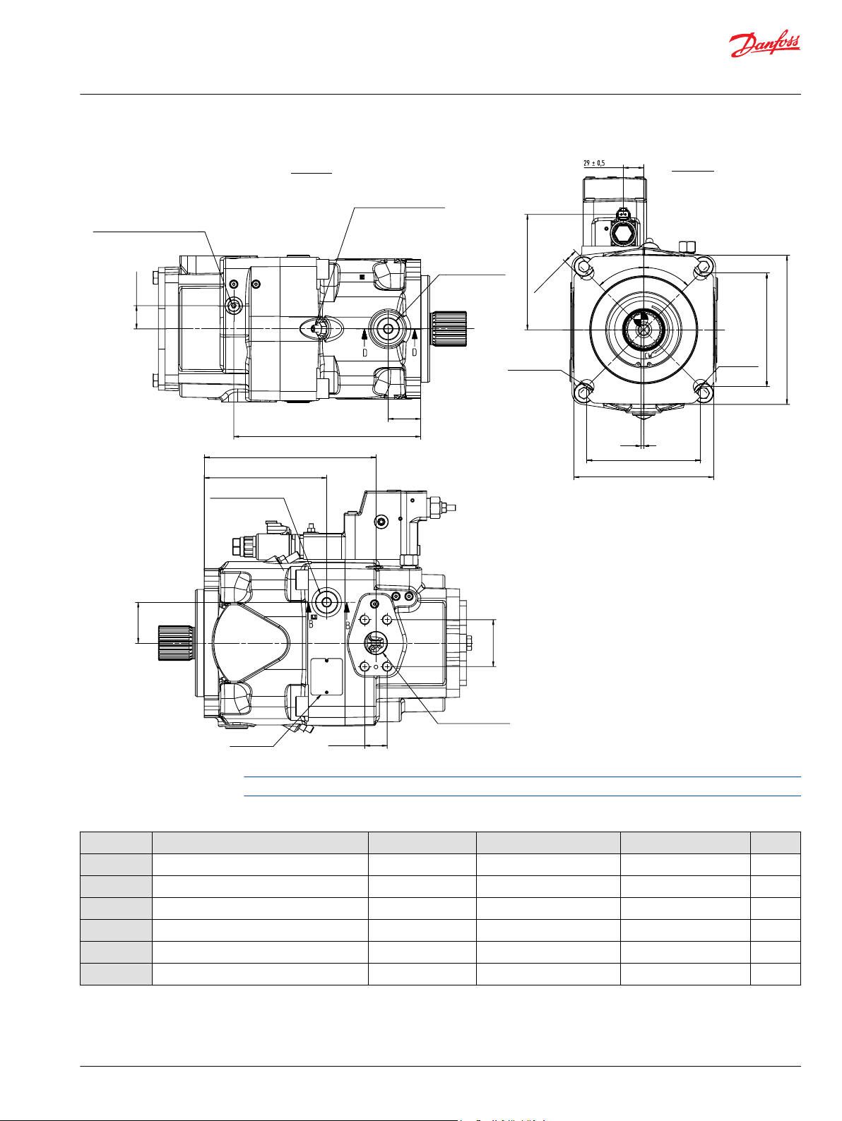
P400511
4x 20.6 ±0.2
161.6 ±0.5
(4)
(198)
(212)
161.6 ±0.5
164.1 ±0.8
Ø
21
+0.021
0
3x Ø
20.6
+0.25
-0.13
View U
45°±1°
45°±1°
33 ±0.5
265.5 ±1.2
46 ±0.8
View X
Servo pressure gauge port“ M4”
Max displacement limiter
DIN 3852 M12x1.5;
12.5 Full thread depth
Drain port “L3”
DIN 3852 M26x1.5;
14 Full thread depth
58 ±0.8
66.6 ±0.2
244 ±1.2
31.8 ±0.2
174 ±1.2
Drain port “L1”
DIN 3852 M26x1.5;
14.5 Full thread depth
Outlet port “
B”
1 1/4 in;SAE J518
M14x2;
23 Full thread depth
Paint free
Name plate
Paint free
Technical Information
D1 High Power Open Circuit Pumps Size 130/145/193/260
Installation Drawings
Port Descriptions
Ports Description Standard Size
B
S
L1, L2, L
M
4
M
B
E
1)
For required torque, please refer to D1P tightening torque on page 94.
2)
O = Open, must be connected (closed by plastic plug on delivery) / X = Closed (closed by metal plug on delivery).
3)
Depending on installation position, one of L1 ,L2 and L3 must be connected (please refer to Installation Notes).
Max. pressure (bar [psi]) State
Before finalizing your design, please request a certified drawing.
Outlet port, Fixing thread SAE J518, DIN13 1 ¼ in, M14 x 2; 23 deep 400 [5802] O
1)
Suction port, Fixing thread SAE J518, DIN13 3 in, M16 x 2; 24 deep 2 [29] O
Drain port DIN 3852 M26 x 1.5; 14.5, 16, 14 deep 2 [29] X
3
Measurement point, servo-piston chamber DIN 3852 M12 x 1.5; 12.5 deep 400 [5802] X
Measurement point, outlet port DIN 3852 M12 x 1.5; 12.5 deep 400 [5802] X
External control port DIN 3852 M14 x 1.5; 12 deep 200 [2901] X
2)
3)
©
Danfoss | December 2021 BC157786485289en-000501 | 53
Page 54

10 ± 0.8
5.2 ± 0.5
45 ± 1
(65)
43.5
36 ± 2
12 ± 2
Ø105.5±0.25
Ø23±0.2
Ø17±0.2
M16 x2-6H THD
1)
0
- 0.5
Ø49.6
0
- 0.16
Ø44.5
+0.12
0
P400085
Mating coupling must not
protrude beyond this point
Spline data
Number of teeth : 24
Modules : 2
Pressure angle : 30°
Pitch Ø : Ø48
Type of fit : Flat root side
Per : DIN 5480 Class 9g
Paint free
Per SAE J744
Flange 152-4
Mounting
flange
Full thd
10 ± 0.8
44 ± 1
(77)
5.2 ± 0.5
12 ± 2
Ø105.5±0.25
Ø34.5±0.1
Ø23±0.2
Ø17±0.2
5/8-11 UNC-2B THD
1)
55
0
- 0.5
Ø 44.45
0
- 0.127
P400424
Mating coupling must not
protrude beyond this point
Spline data
Number of teeth : 13
Pitch fraction : 8/16
Pressure angle : 30°
Pitch Ø : Ø41.275
Type of fit : Fillet root side
Per : ANSI B92.1-1996.
Class 5
Paint free
Per SAE J744Flange 152-4,
Mounting flange
36 ± 2
Full thd
Technical Information
D1 High Power Open Circuit Pumps Size 130/145/193/260
Installation Drawings
Input shaft
D1P 130/145 shaft specifications
Shaft torque and dimensions
Code Description Maximum Torque
Rating
T Splined shaft DIN
5480, W50 x 2 x 30 x
3100 N•m [27437
lbf•in]
24 x 9g
Drawing
(2)
:43.5 mm [1.71 in]
S Splined shaft SAE
J744, 1 3/4 in. 13T,
Min. active spline length
1528 N•m [13524
lbf•in]
8/16 DP
54 | © Danfoss | December 2021 BC157786485289en-000501
Min. active spline length
(2)
:55 mm [2.71 in]
Page 55

Paint free
Mounting flange surface
Flange 152-4
SAE-D J744 4 bolt
M5 x 0.8
Key, AS14x9x80
M16x2-6H THD
Mating coupling must not
protrude beyond this point
80
+0.3
0
1.5
+0.1
0
Ø 105.5 ± 0.25
(53.5)
Ø50
0
-0.5
Ø 23 ± 0.2
Ø 17 ± 0.2
5.2 ± 0.5
12 ± 2
36 ± 2
Full THD
44 ± 1
82 ± 0.1
92 ± 0.5
R1 ± 0.1
Ø 55
+0.02
+0.009
Paint free
Mounting flange surface
Flange 152-4
SAE-D J744 4 bolt
(1.5)
Key-SQ, 0.4375 x 3.000, hard
(49.3)
Mating coupling must not
protrude beyond this point
77.7 ± 0.8
Ø 105.5 ± 0.25
Ø 44.45
0
-0.05
4.4
± 0.5
9.5 ± 2
28 ± 2
Full THD
36 ± 1
100 ± 0.5
92
+0.1
0
R1.5 ± 0.1
Ø 55 ± 0.015
Ø 13 ± 0.2
Ø 18.1 ± 0.2
7/16-14UNC-2B
Technical Information
D1 High Power Open Circuit Pumps Size 130/145/193/260
Installation Drawings
Shaft torque and dimensions (continued)
Code Description Maximum Torque
Rating
P Straight keyed shaft,
DIN 6885, AS14 x 9 x
1411 N•m [12488
lbf•in]
80
Drawing
K SAE J744 (D/E) 3in
straight keyed shaft,
0.4375 x 3.000 in
1787 N•m [15816
lbf•in]
1) Center bore according to DIN 332 (thread according to DIN 13)
2) Minimum active spline length for the specified torque ratings
©
Danfoss | December 2021 BC157786485289en-000501 | 55
Page 56

360 max
2)
310 max
1)
94
47
2xØ6.9±0.1
P400269
No auxiliary
mounting pad
(NN)
2xØ11.2±0.1
7±0.2 depth
counter bore
O-ring seal required
Ref Ø75.86 IDx2.62
cross section
1)
Without charge pump
2)
With charge pump
Mounting
flange
54.8 min
128
64
128
64
106.4
53.2
4xØ20 ±0.2
4xØ13.5
±0.2
Ø88.621
+0.13
+0
Ø82.55
+0.065
+0.03
R0.5
max
2xM10x1.5-6H
2xM10x1.5-6H
1.96±0.08
8.1±0.13
11.65 min
1)
Without charge pump
2)
With charge pump
329 max
1)
363 max
2)
P400271
Spline data
Number of teeth : 9
Pitch fraction : 16/32
Pressure angle : 30°
Pitch Ø : Ø14.288
Type of fit : Fillet root side
Per : ANSI B92.1-1996
Class 6
Mating shaft shoulder must
Not protrude beyond this point
Mating shaft top must not
Protrude beyond this point
Mounting flange
Shaft clearance
Shaft clearance
O-ring seal required
Ref Ø82.2IDx2.62cross
section
Auxiliary mounting pad
For mating flange 82-2
Per SAE J744(A)
Paint free
12.5 min THD depth
13±0.1 depth
through hole
19 min THD depth
Technical Information
D1 High Power Open Circuit Pumps Size 130/145/193/260
Installation Drawings
Aux mounting flange
Size 130/145: Option NN (No Coupling)
Specifications
Option Coupling
NN No coupling
Size 130/145: Option A1 (SAE-A, 9 teeth)
56 | © Danfoss | December 2021 BC157786485289en-000501
Specifications
Option Coupling Max torque
A1 5/8 in, 9T, 16/32 DP 205 N•m [1814.40 lbf•in]
Page 57
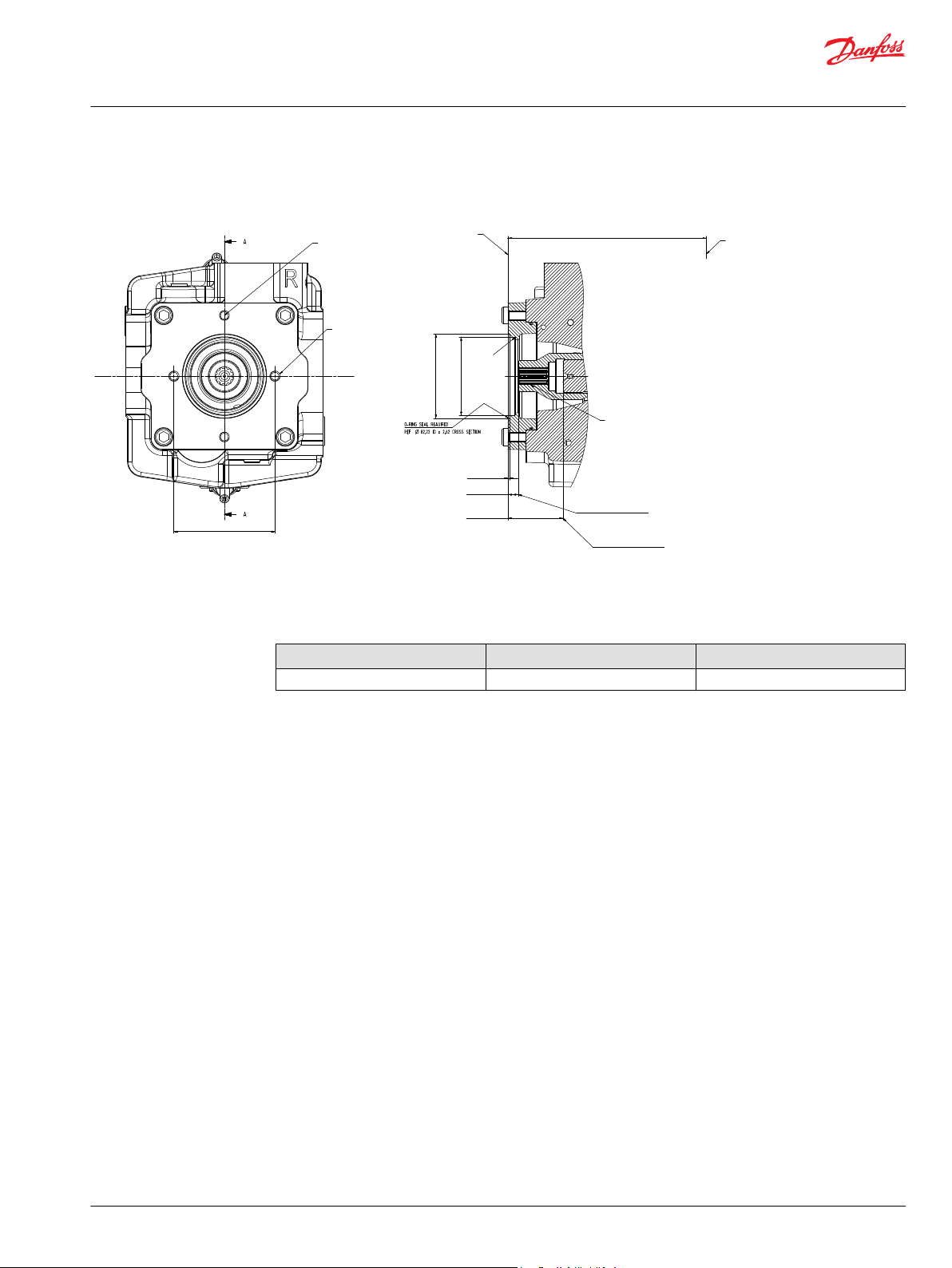
2x lifting hold
M10x1.5
19 full thread depth
2x adapter screw hole
M10x1.5
12.5 full thread depth
106.4 ± 0.1
Auxiliary mounting pad
for mating flange 82-2
per SAE J744 (A)
Mounting flange
R 0.8 ± 0.4
1.96 ± 0.08
Spline data
Number of teeth: 11
Pitch fraction: 16/32
Pressure angle: 30
Pitch: 17/463
Type of fit: fillet root side
Per: ANSI B92, 1-1996, class 6
Mating shaft shoulder must
not protrude beyond this point
Mating shaft must not
protrude beyond this point
O-ring seal required
Ref Ø 82.22 ID x 2.62 cross section
Ø 88.621
+0.13
0
Ø 82.55
+0.065
+0.03
329 max
1)
363 max
2)
11.1
1)
13.3
2)
57
1)
Without charge pump
2)
With charge pump
Technical Information
D1 High Power Open Circuit Pumps Size 130/145/193/260
Installation Drawings
Size 130/145: Option A2 (SAE-A, 11 teeth)
Specifications
Option Coupling Max torque
A2 3/4in, 11T, 16/32DP Pending
©
Danfoss | December 2021 BC157786485289en-000501 | 57
Page 58

P400272
56
Spline data
Number of teeth:13
Pitch fraction :16/32
Pressure angle :
30°
PitchØ :
Ø20.638
Type of fit :
fillet root side
Per
:
ANSI B92.1-1996
CLASS 6
Mating shaft shoulder must
Not protrude beyond this point
Mating shaft top must not
Protrude beyond this point
19 min THD depth
9±0.1 depth
through hole
Mounting flange
O-ring seal
required
Ref Ø94.92IDx2.62
cross section
Paint free
max
2)
128
64
128
64
4xØ20±0.2
4xØ13.5
±0.2
Ø107.82
+0.13
+0
Ø101.6
+0.06
+0.03
R0.5
max
1.96±0.08
14.4±0.2
15.15 min
363
1)
Without charge pump
2)
With charge pump
max
1)
329
Auxiliary mounting pad
For mating flange 101-2
Per SAE J744(B)
4xM12x1.75-6H
45°
min
Shaft clearance
Shaft clearance
Ø146
P400272
56
Spline data
Number of teeth:15
Pitch fraction :16/32
Pressure angle :
30°
PitchØ :
Ø23.812
Type of fit :
fillet root side
Per
:
ANSI B92.1-1996
CLASS 6
Mating shaft shoulder must
Not protrude beyond this point
Mating shaft top must not
Protrude beyond this point
19 min THD depth
9±0.1 depth
through hole
Mounting flange
O-ring seal
required
Ref Ø94.92IDx2.62
cross section
Paint free
max
2)
128
64
128
64
4xØ20±0.2
4xØ13.5
±0.2
Ø107.82
+0.13
+0
Ø101.6
+0.06
+0.03
R0.5
max
1.96±0.08
14.4±0.2
15.15 min
363
1)
Without charge pump
2)
With charge pump
max
1)
329
Auxiliary mounting pad
For mating flange 101-2
Per SAE J744(B)
4xM12x1.75-6H
45°
min
Shaft clearance
Shaft clearance
Ø146
Technical Information
D1 High Power Open Circuit Pumps Size 130/145/193/260
Installation Drawings
Size 130/145: Option B1 (SAE-B, 13 teeth)
Specifications
Option Coupling Max torque
B1 7/8 in, 13T, 16/32 DP 411 N•m [3637.66 lbf•in]
Size 130/145: Option B2 (SAE-B, 15 teeth)
58 | © Danfoss | December 2021 BC157786485289en-000501
Specifications
Option Coupling Max torque
B2 1in, 15T, 16/32DP Pending
Page 59

Ø 146
4x M12x1.75; 19 deep
O-ring seal required
Ref Ø 101.26 ID x 2.62
cross section
12.1 min
shaft clearance
55 min
shaft clearance
Mating shaft shoulder must
not protrude beyond this point
Mating shaft must not
protrude beyond this point
Spline data
Number of teeth: 13
Pitch fraction: 16/32
Pressure angle: 30
Pitch Ø: 20.638
Type of fit: fillet root side fit
Per: ANSI B92, 1-1996, class 6
Mounting flange
363 max
Auxiliary mounting pad
For mounting flange 101-2
Per SAE J744 (B)
Ø107.82
+0.13
0
Ø101.6
+0.06
+0.03
1.96 ± 0.08
P400425
59
Spline data
Number of teeth :
:
:
:
:
:
14
Pitch fraction 12/24
Pressure angle 30°
PitchØ Ø29.633
Type of fit fillet root side
Per ANSI B92.1-1996 CLASS 6
Mating shaft shoulder must
Not protrude beyond this point
Mating shaft top must not
Protrude beyond this point
13±0.2 THD depth
Mounting flange
O-ring seal
required
Ref Ø120.32 IDx2.62
cross section
Paint free
114.5
57.25
114.5
57.25
Ø134.06
+0.13
+0
Ø127
+0.07
+0.03
R0.4±0.12
1.96±0.08
15±0.1
27 min
401±2
2)
367±2
1)
Auxiliary mounting pad
For mating flange 127-2&4
Per SAE J744(C)
4xM12x1.75-6H
min
Shaft clearance
Shaft clearance
181
2xM16x2-6H
13±0.2 THD depth
4x13±0.2
4xØ13±0.2
8x64
R0.8±0.4
1)
Without charge pump
2)
With charge pump
Technical Information
D1 High Power Open Circuit Pumps Size 130/145/193/260
Installation Drawings
Size 130/145: Option BA (SAE-B, 13 teeth)
Specifications
Option Coupling Max torque
BA 7/8in, 13T, 16/32DP 411 N•m [3637.66 lbf•in]
Size 130/145: Option C5 (SAE-C, 14 teeth)
©
Danfoss | December 2021 BC157786485289en-000501 | 59
Specifications
Option Coupling Max torque
C5 1 ¼ in, 14T 12/24 DP 1164 N•m [10302.27 lbf•in]
Page 60

69 min
128
64
128
64
161.6
80.8
4xØ19.4
±0.2
4xØ13±0.2
Ø158.4±0.05
Ø152.4
+0.07
+0.03
R0.5
max
Paint
free
1.96±0.08
15±0.1
21.7 min
374 max
2)
340 max
1)
161.6
80.8
4xM20x2.5-6H
28 min THD depth
P400273
Mating shaft shoulder must
Not protrude beyond this point
Mating shaft top must not
Protrude beyond this point
Mounting
flange
Shaft clearance
Shaft clearance
O-ring seal required
Ref Ø145.72IDx2.62
cross section
Auxiliary mounting pad
For mating flange 152-4
Per SAE J744(D)
15±0.1 depth
through hole
Spline data
Number of teeth: 24
Modules : 2
Pressure angle : 30°
Pitch Ø : Ø48
Type of fit : Flat root side
Per : DIN 5480
Class 9H
1)
Without charge pump
2)
With charge pump
Technical Information
D1 High Power Open Circuit Pumps Size 130/145/193/260
Installation Drawings
Size 130/145: Option D5 (SAE-D, 24 teeth)
Specifications
Option Coupling Max torque
D5 N50 x 2 x 30 x 24 x 9H 1164 N•m [10302.27 lbf•in]
Before finalizing your design, please request a certified drawing.
60 | © Danfoss | December 2021 BC157786485289en-000501
Page 61

Y
Z
U
421.1 ±2
381 ±1.2
319.4 ±1.2
15.9 ±0.5
25.8 ±1
66 ±0.8
226.5 ±1.2
120.7 ±0.25
(162.7)
(187)
(11)
Ø
1
.
5
6
1
0
5
0
.
0
-
69.9 ±0.25
190 ±1.2
116 ±0.8 116 ±0.8
131.3 ±1.2 131.3 ±1.2
68 ±0.8
271 ±1.2
61 ±1.2
321 ±1.2
(378)
P400122
Inlet port “S”
3 1/2 in;SAE J518
M16x2
25 Full thread depth
Paint free
Drain port “L2”
Paint free
DIN 3852 M33x2;
14 Full thread depth
Approximate
Center of gravity
Approximate
Center of gravity
View Z
View Y
Outlet port “B” Inlet por t “S”
Min displacement limiter
Outlet pressure gauge port “MB”
Control solenoid connector “E2 ”
DIN3852 M12x1.5;
13 Full thread depth
Mounting flange surface
Flange 165-4
SAE-E J744 4 bolt
4x
Adapter screw hole
M12x1.75
15 Full thread depth
Lift hole
DIN 13 M12x1.75;
14 Full thread depth
External control supply port “E”
DIN3852 M14x1.5;
14 Full thread depth
T (Power control)
P (Pressure
compensated control)
Deutsch, 24V, 2-PIN
Paint free
Technical Information
D1 High Power Open Circuit Pumps Size 130/145/193/260
Installation Drawings
Size 193
Dimensions (mm) and port descriptions
Size 193: TPE2 w/ Charge Pump
Control : TPE2
Power Control (T) + Pressure Compensated Control (P) + Electric Displacement Control (E2)
Auxiliary flange : B1
©
Danfoss | December 2021 BC157786485289en-000501 | 61
Before finalizing your design, please request a certified drawing.
Page 62

25 ±0.5
66 ±0.8
79.4 ±0.25
287 ±1.2
271.1 ±1.2
36.5 ±0.25
190 ±1.2
61 ±0.8
Z
224.5 ±0.5
(262.6)
34 ±0.8
(3)
CW
224.5 ±0.5
(268.5)
173.2 ±1.2
Ø21
+0.021
0
3x Ø20.6
+0.25
-0.13
P400123
View U
View X
Max displacement limiter
Drain port “L3”
DIN 3852 M33x2;
18 Full thread depth
Lift hole
DIN 13 M12x1.75;
14 Full thread depth
Servo pressure gauge port “M4”
DIN3852 M12x1.5;
13 Full thread depth
Drain port “L1B”
DIN 3852 M33x2;
14 Full thread depth
Outlet port “ “
1 1/2 in;SAE J518
M16x2
25 Full thread depth
Paint free
Name plate
Paint free
Technical Information
D1 High Power Open Circuit Pumps Size 130/145/193/260
Installation Drawings
Before finalizing your design, please request a certified drawing.
Port Descriptions
Ports Description Standard Size
Outlet port, Fixing thread SAE J518, DIN13 1 1/2 in, M16 x 2; 25 deep 400 [5802] O
B
S
L1, L2, L
M
4
M
B
E
1)
For required torque, please refer to D1P tightening torque on page 94
2)
O = Open, must be connected (closed by plastic plug on delivery) / X = Closed (closed by metal plug on delivery)
3)
Depending on installation position, one of L1 ,L2 and L3 must be connected (please refer to Installation Notes).
4)
If E port is not used, remove the shuttle valve and lock port by seal plug.
Suction port, Fixing thread SAE J518, DIN13 3 1/2 in, M16 x 2; 25 deep 2 [29] O
Drain port DIN 3852 M33 x 2; 14,14, 18 deep 2 [29] X
3
Measurement point, servo-piston chamber DIN 3852 M12 x 1.5; 13 deep 400 [5802] X
Measurement point, outlet port DIN 3852 M12 x 1.5; 13 deep 400 [5802] X
External control port DIN 3852 M14 x 1.5; 14 deep 200 [2901] X
1)
Max. pressure (bar [psi]) State
2)
3)
4)
62 | © Danfoss | December 2021 BC157786485289en-000501
Page 63

Y
Z
U
381 ±1.2
319.4 ±1.2
317.2 ±1.2
15.9 ±0.5
25.8 ±1
66 ±0.8
156 ±1.2
178 ±1.2
120.7 ±0.25
(162.7)
(183)
(7)
Ø
1
.
5
6
1
0
5
0
.
0
-
69.9 ±0.25
190 ±1.2
116 ±0.8
116 ±0.8
131.3 ±1.2 131.3 ±1.2
68 ±0.8
403 ±2
271 ±1.2
(379)
X
P400192
View Z
View Y
Inlet port “S”
3 1/2 in;SAE J518
M16x2
25 Full thread depth
Paint free
Drain port “L2”
Paint free
DIN 3852 M33x2;
14 Full thread depth
Approximate
Center of gravity
Outlet port “B” Inlet port “S”
Mounting flange surface
Flange 165-4
SAE-E J744 4 bolt
Outlet pressure gauge port “MB”
DIN3852 M12x1.5;
13 Full thread depth
LS Pressure signal port “X”
M14x1.5;
12 Full thread dpth
T (Power control)
P (Pressure
compensated control)
S (Load sensing control)
Min displacement limiter
Lift hole
DIN 13 M12x1.75;
14 Full thread depth
Technical Information
D1 High Power Open Circuit Pumps Size 130/145/193/260
Installation Drawings
Size 193: TPSN w/ Charge Pump
Control : TPSN
Power Control (T) + Pressure Compensated Control (P) + Load Sensing Control (S)
Auxiliary flange : NN
Before finalizing your design, please request a certified drawing.
©
Danfoss | December 2021 BC157786485289en-000501 | 63
Page 64

25 ±0.5
66 ±0.8
79.4 ±0.25
287 ±1.2
271.1 ±1.2
36.5 ±0.25
190 ±1.2
61 ±0.8
131 ±0.8
(4)
CW
224.5 ±0.5
(268.5)
Ø
21
+0.021
0
3x Ø
20.6
+0.25
-0.13
224.5 ±0.5
(262.6)
P400193
View U
View X
View Y
Max displacement limiter
Drain port “L3”
DIN 3852 M33x2;
18 Full thread depth
Lift screwed hole
DIN 13 M12x1.75;
14 Full thread depth
Servo pressure gauge port “M4”
DIN3852 M12x1.5;
13 Full thread depth
Drain port “L1”
DIN 3852 M33x2;
18 Full thread depth
Outlet port “
B”
1 1/2 in;SAE J518
M16x2
21 Full thread depth
No paint
Name plate
Paint free
Technical Information
D1 High Power Open Circuit Pumps Size 130/145/193/260
Installation Drawings
Port Descriptions
Ports Description Standard Size
B
S
L1, L2, L
M
4
M
B
X
1)
For required torque, please refer to D1P tightening torque on page 94.
2)
O = Open, must be connected (closed by plastic plug on delivery) / X = Closed (closed by metal plug on delivery).
3)
Depending on installation position, one of L1 ,L2 and L3 must be connected (please refer to Installation Notes).
Outlet port, Fixing thread SAE J518, DIN13 1 1/2 in, M16 x 2; 25 deep 400 [5802] O
Suction port, Fixing thread SAE J518, DIN13 3 1/2 in, M16 x 2; 25 deep 2 [29] O
Drain port DIN 3852 M33 x 2; 14, 14, 18 deep 2 [29] X
3
Measurement point, servo-piston chamber DIN 3852 M12 x 1.5; 13 deep 400 [5802] X
Measurement point, outlet port DIN 3852 M12 x 1.5; 13 deep 400 [5802] X
LS port DIN 3852 M14 x 1.5; 12 deep 400 [5802] O
Before finalizing your design, please request a certified drawing.
1)
Max. pressure (bar [psi]) State
2)
3)
64 | © Danfoss | December 2021 BC157786485289en-000501
Page 65
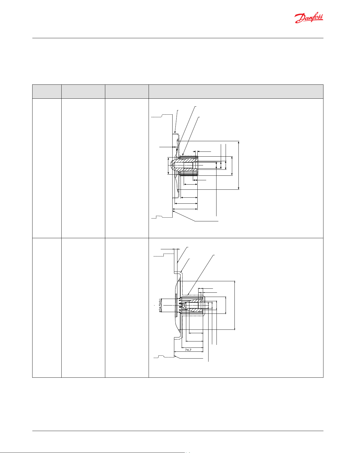
10.4 ± 0.8
5.2 ± 0.5
60 ± 1
44
38 ± 2
12 ± 2
Ø44.5±0.1
Ø126±0.1
Ø23±0.2
Ø17±0.2
0
- 0.5
Ø49.6
0
- 0.1
P400086
(66)
Per SAE J744
Flange 165-4
Mounting flange
Paint free
Spline data
Number of teeth : 24
Modules : 2
Pressure angle : 30°
pitch : Ø 48
Type of fit : flat root side fit
Per : DIN 5480 CLASS 9g
Mating coupling must not
Protrude beyond this point
FULL THD
M16 x2-6H THD
1)
7.8 ± 0.8
12 ± 2
5.2 ± 0.5
36 ± 2
44 ± 1
55
Ø126±0.1
Ø23±0.2
Ø17±0.2
0
- 0.5
Ø44.45
0
- 0.127
P400426
Per SAE J744
Flange 165-4
Mounting flange
Paint free
Spline data
Number of teeth : 13
Pitch friction : 8/16
Pressure angle : 30°
pitch : Ø 41.275
Type of fit : Fillet root side
Per : ANSI B92.1-1996. Class 5
Mating coupling must not
Protrude beyond this point
FULL THD
5/8-11 UNC-2B THD
1)
( )
Technical Information
D1 High Power Open Circuit Pumps Size 130/145/193/260
Installation Drawings
Input shaft
D1P 193 shaft specifications
Code Description Maximum Torque
Rating
T Splined shaft DIN
5480, W50 x 2 x 30 x
3100 N•m [27437
lbf•in]
24 x 9g
S Splined shaft SAE
J744, 1 3/4 in, 13T,
1536 N•m [13595
lbf•in]
8/16 DP
Drawing
Min. active spline length
(2)
:44 mm [1.73 in]
©
Danfoss | December 2021 BC157786485289en-000501 | 65
Min. active spline length
(2)
:55 mm [2.17 in]
Page 66

7.8 ± 0.8
12 ± 2
5.2 ± 0.5
36 ± 2
44 ± 1
Ø126±0.1
Ø40.7±0.1
66
(87.7)
0
- 0.5
Ø50.8
0
- 0.127
P400427
Paint free
Spline data
Number of teeth : 15
Pitch friction : 8/16
Pressure angle : 30°
pitch : Ø 47.625
Type of fit : Fillet root side
Per : ANSI B92.1-1996. Class 5
Mating coupling must not
Protrude beyond this point
FULL THD
Mounting flange
Flange 165-4
Per SAE J744
Ø23±0.2
Ø17±0.2
5/8-11 UNC-2B THD
1)
Technical Information
D1 High Power Open Circuit Pumps Size 130/145/193/260
Installation Drawings
Code Description Maximum Torque
Rating
A Splined shaft SAE
J744, 2 in, 15T, 8/16
2422 N•m [21437
lbf•in]
DP
Drawing
Min. active spline length
(2)
:66 mm [2.60 in]
66 | © Danfoss | December 2021 BC157786485289en-000501
Page 67

Paint free
Mounting flange
Flange 165-4
SAE-E SAE J744 4 bolt
100
+0.5
0
2
+0.2
0
Key, AS16x10x100
M5 x 0.8
Ø 55
0
- 0.06
(59)
Ø 126 ± 0.1
Ø 28 ± 0.2
Ø 21 ± 0.2
M20 x 2.5 THD
42 ± 2
Full THD
105
+0.1
0
112.7 ± 0.5
Mating coupling must not
protrude beyond this point
Ø 60
0
- 0.03
R1 ± 0.1
6 ± 0.5
15 ± 2
55 ± 1
Paint free
Mounting flange
Flange 165-4
SAE-E J744 4 bolt
77.7 ± 0.8
(1.5)
Key-SQ, 0.4175 x 3.000, hard
Ø 126 ± 0.1
Ø 44.45
0
- 0.05
(49.3)
Ø 18.1 ± 0.2
Ø 13 ± 0.2
7/16 - 14UNC-2B THD
4.4 ± 0.5
9.5 ± 2
28 ± 2
Full THD
36 ± 1
R1.5 ± 0.1
92
+ 0.1
0
100 ± 0.5
Mating coupling must not
protrude beyond this point
Ø 60
0
- 0.03
Technical Information
D1 High Power Open Circuit Pumps Size 130/145/193/260
Installation Drawings
Code Description Maximum Torque
Rating
P Straight keyed shaft,
DIN 6885,
2195 N•m [19427
lbf•in]
AS16x10x100
K SAE J744 (D/E) 3in
straight keyed shaft,
1787 N•m [15816
lbf•in]
0.4375x3.000 in
Drawing
©
Danfoss | December 2021 BC157786485289en-000501 | 67
1) Center bore according to DIN 332 (thread according to DIN 13)
2) Minimum active spline length for the specified torque ratings
Page 68

P400274
403 max
145±0.1
72.5±0.05
145±0.1
72.5±0.05
4xØ17±0.2
4xØ26±0.2
3.5±0.1 depth
through hole
No auxiliary
mounting pad
(NN)
O-ring seal required
Ref Ø158.42IDx2.62cross
section
Mounting
flange
P400275
106.4±0.1
53.2±0.05
1.96±0.08
8.1±0.13
54.8 min
2xM10x1.5-6H
13 min THD depth
Ø82.55
+0.065
+0.03
Ø88.621
+0.13
+0
145±0.2
72.5±0.1
145±0.2
72.5±0.1
4xØ26±0.2
4x Ø17±0.2
6±0.1 depth
through hole
394
R0.5
max
11.6 min
2x M10 x1.5-6H
thread through
hole
Paint free
Auxiliary mounting pad
For mating flange 82-2
Per SAE J744(A)
Mounting flange
max
O-ring seal
required
Ref Ø82.2IDx2.62
cross section
Mating shaft shoulder must
Not protrude beyond this point
Mating shaft top must not
Protrude beyond this point
Shaft clearance
Shaft clearance
Spline data
Number of teeth :9
Pitch fraction:16/32
Pressure angle :30°
PitchØ :Ø14.288
Type of fit :fillet root side
Per :ANSI B92.1-1996
CLASS 6
Technical Information
D1 High Power Open Circuit Pumps Size 130/145/193/260
Installation Drawings
Aux mounting flange
Size 193: Option NN (No Coupling)
Specifications
Option Coupling
NN No coupling
Size 193: Option A1 (SAE-A, 9 teeth)
Option Coupling Max torque
A1 5/8 in, 9T, 16/32 DP 205 N•m [1814.40 lbf•in]
Specifications
68 | © Danfoss | December 2021 BC157786485289en-000501
Page 69

P400578
106.4±0.1
53.2±0.05
1.96±0.08
8.1±0.13
55.3
2xM10x1.5-6H
13 min THD depth
Ø82.55
+0.065
+0.03
Ø88.621
+0.13
+0
145±0.2
72.5±0.1
145±0.2
72.5±0.1
4xØ26±0.2
4xØ17±0.2
6±0.1 depth
through hole
394
R0.5
max
12.3
2xM10x1.5-6H
thread through
hole
Paint free
Auxiliary mounting pad
For mating flange 82-2
Per SAE J744(A)
Mounting flange
max
O-ring seal
required
Ref Ø82.2IDx2.62
cross section
Mating shaft shoulder must
Not protrude beyond this point
Mating shaft top must not
Protrude beyond this point
min
Shaft clearance
min
Shaft clearance
Spline data
Number of teeth :13
Pitch fraction :16/32
Pressure angle :30°
PitchØ :Ø20.638
Type of fit :fillet root side fit
Per :ANSI B92.1-1996 CLASS 6
64.8 min
1.96±0.08
12 min
(13.9)
404 max
145±0.1
72.5±0.05
145±0.1
72.5±0.05
Ø146
45°±1°
4xØ26±0.2
4xØ17±0.2
4xM12x1.75-6H
Ø107.823
+0.13
+0
Ø101.6
+0.065
+0.03
R0.5
max
P400276
Paint
free
15 min THD depth
Mating shaft shoulder must
Not protrude beyond this point
Mating shaft top must not
Protrude beyond this point
Mounting
flange
Shaft clearance
Shaft clearance
O-ring seal
required
Ref Ø94.92IDx2.62
cross section
Auxiliary mounting pad
For mating
flange 101-2
Per SAE J744(B)
6±0.1 depth
through hole
Spline data
Number of teeth: 13
Pitch fraction : 16/32
Pressure angle : 30°
Pitch Ø : Ø20.638
Type of fit : Fillet root side
Per : ANSI B92.1-1996
class 6
Technical Information
D1 High Power Open Circuit Pumps Size 130/145/193/260
Installation Drawings
Size 193: Option A3 (SAE-A, 13 teeth)
Specifications
Option Coupling Max torque
A3 7/8 in, 13T, 16/32 DP 619 N•m [5478.61 lbf•in]
Size 193: Option B1 (SAE-B, 13 teeth)
©
Danfoss | December 2021 BC157786485289en-000501 | 69
Specifications
Option Coupling Max torque
B1 7/8 in, 13T, 16/32 DP 411 N•m [3637.66 lbf•in]
Page 70

Ø 146
4x M12x1.75;
16 deep
O-ring seal required
Ref Ø 101.26 ID x 2.62
cross section
Mating shaft shoulder must
not protrude beyond this point
Mating shaft must not
protrude beyond this point
“C” min
shaft clearance
“B” min
shaft clearance
Spline data
Number of teeth: 15
Pitch fraction: 16/32
Pressure angle: 30°
Pitch Ø: 23.813
Type of fit: fillet root side fit
Per: ANSI B92, 1-1006, class 6
Mounting flange
“A” max
Auxiliary mounting pad
For mating flange 101-2
Per SAE J744 (B)
Ø 107.8
+0.13
0
Ø 101.6
+0.06
+0.03
1.96 ± 0.08
Technical Information
D1 High Power Open Circuit Pumps Size 130/145/193/260
Installation Drawings
Size 193: Option B2 (SAE-B, 15 teeth)
Legend
Dimension Y2 N3
A 404 369.8
B 12.2 12.3
C 65 63.2
Specifications
Option Coupling Max torque
B2 1in, 15T, 16/32DP Pending
70 | © Danfoss | December 2021 BC157786485289en-000501
Page 71

Ø 146
Ø 107.8
+0.13
0
Ø 101.6
+0.06
+0.03
O-ring seal required
Ref Ø 101.26 ID x 2.62
cross section
Spline data
Number of teeth: 13
Pitch fraction: 16/32
Pressure angle: 30
Pitch Ø: 20.638
Type of fit: fillet root side fit
Per: ANSI B92, 1-1996, class 6
Mounting flange
“A” max
Auxiliary mounting pad
For mating flange 101-2
Per SAE J744 (B)
1.96 ± 0.08
“B” min
shaft clearance
“C” min
shaft clearance
Mating shaft shoulder must
not protrude beyond this point
Mating shaft must not
protrude beyond this point
Technical Information
D1 High Power Open Circuit Pumps Size 130/145/193/260
Installation Drawings
Size 193: Option BA (SAE-B, 13 teeth)
Legend
Dimension Value
A 404
B 12
C 64
Specifications
Option Coupling Max torque
BA 7/8in, 13T, 16/32DP 411 N•m [3637.66 lbf•in]
©
Danfoss | December 2021 BC157786485289en-000501 | 71
Page 72

Ø 146
4x M12x1.75;
16 deep
Auxiliary mounting pad
For mating flange 101-2
Per SAE J744 (B)
Ø107.8
+0.13
0
Ø101.6
+0.06
+0.03
B min
shaft clearance
C min
shaft clearance
Mating shaft must not
protrude beypnd this point
Mating shaft shoulder must
not protrude beyond this point
Spline data
Number of teeth: 13
Pressure angle: 30
Pitch Ø: 20.638
Type of fit: fillet root side fit
Per: ANSI B92, 1-1996, class 6
Mounting flange
A max
2 ± 0.08
Technical Information
D1 High Power Open Circuit Pumps Size 130/145/193/260
Installation Drawings
Size 193: Option BB (SAE-B, 13 teeth)
Legend
Dimension Value
A 404
B 11.6
C 63.4
Specifications
Option Coupling Max torque
BB 7/8in, 13T, 16/32DP 411 N•m [3637.66 lbf•in]
72 | © Danfoss | December 2021 BC157786485289en-000501
Page 73
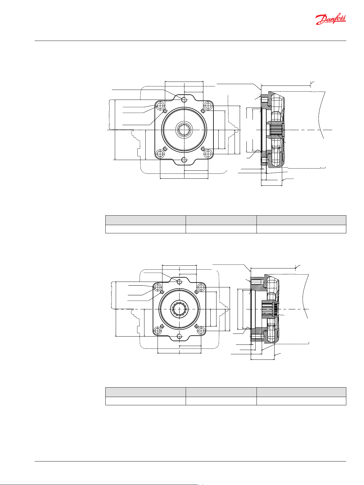
Ø134.06
+0.13
0
Ø127
+0.07
+0.03
400 max
R0.5
max
1.96±0.08
14.5 min
62.5 min
15±0.1
4xØ26±0.2
4xØ17±0.2
2xM16x2-6H
4xM12x1.75-6H
145±0.2
72.5±0.1
145±0.2
72.5±0.1
181±0.2
90.5±0.1
114.5±0.2
57.25±0.1
114.5±0.2
57.25±0.1
P400277
19 min THD depth
Mating shaft shoulder must
Not protrude beyond this point
Mating shaft top must not
Protrude beyond this point
Mounting
flange
Shaft clearance
Shaft clearance
O-ring seal required
Ref Ø120.32IDx2.62
cross section
Paint free
For mating flange 127-4
Per SAE J744(C)
11.5±0.1 depth
through hole
Spline data
Number of teeth: 14
Pitch fraction : 12/24
Pressure angle : 30°
Pitch Ø : Ø29.633
Type of fit : Fillet root side
Per : ANSI B92.1-1996
class 6
19 min THD depth
Auxiliary mounting pad
P400579
33 min THD
depth
R0.5
max
Paint free
Auxiliary mounting pad
For mating flange 127-4
Per SAE J744(C)
Mounting flange
max
O-ring seal
required
Ref Ø120.32IDx2.62
cross section
Mating shaft shoulder must
Not protrude beyond this point
Mating shaft top must not
Protrude beyond this point
min
Shaft clearance
Spline data
Number of teeth :13
Pitch fraction :8/16
Pressure angle :30°
PitchØ :Ø41.275
Type of fit :fillet root side fit
Per :ANSI B92.1-1996
CLASS 6
Ø134.1
+0.13
0
Ø127
+0.07
+0.03
424
1.96±0.08
14.5
62.5
15±0.1
4xØ26±0.2
4xØ17±0.2
2xM16x2-6H
4xM12x1.75-6H
145±0.2
72.5±0.1
145±0.2
72.5±0.1
181±0.2
90.5±0.1
114.5±0.2
57.2±0.1
114.5±0.2
57.3±0.1
32.5±0.2 depth
counter bore
19 min THD depth
min
Shaft clearance
Technical Information
D1 High Power Open Circuit Pumps Size 130/145/193/260
Installation Drawings
Size 193: Option C5 (SAE-C, 14 teeth)
Specifications
Option Coupling Max torque
C5 1 1/4 in, 14T, 12/24 DP 1289 N•m [11408.61 lbf•in]
Size 193: Option C9 (SAE-C, 13 teeth)
©
Danfoss | December 2021 BC157786485289en-000501 | 73
Specifications
Option Coupling Max torque
C9 1 3/4 in, 13T, 8/16 DP 1790 N•m [15842.83 lbf•in]
Page 74

P400580
80
1.96±0.08
39.1
15±0.1
427
161.6±0.1
80.8±0.05
161.6±0.1
80.8±0.05
Ø158.4±0.05
Ø152.4
+0.07
+0.03
R0.5
max
Paint free
4xM20x2.5-6H
23 FULL THREAD
DEPTH
Auxiliary mounting pad
For mating flange 152-4
Per SAE J744(D)
Mounting flange
max
O-ring seal
required
Ref Ø145.72IDx2.62
cross section
Spline data
Number of teeth :
:
:
:
:
:
13
Pith fraction 8/16
Pressure angle 30°
PitchØ Ø41.275
Type of fit fillet root side fit
Per ANSI B92.1-1996
CLASS 6
Mating shaft shoulder must
Not protrude beyond this point
Mating shaft top must not
Protrude beyond this point
min
min
Shaft clearance
Shaft clearance
68.9 min
1.96±0.08
30.6 min
15±0.1
426 max
161.6±0.1
80.8±0.05
161.6±0.1
80.8±0.05
Ø158.4±0.05
Ø152.4
+0.07
+0.03
R0.5
max
4xM20x2.5-6H
P400278
Paint free
22 min THD depth
Mating shaft shoulder must
Not protrude beyond this point
Mating shaft top must not
Protrude beyond this point
Mounting
flange
Shaft clearance
Shaft clearance
O-ring seal
required
Ref Ø145.72
IDx2.62
cross section
Auxiliary mounting pad
For mating
flange 152-4
Per SAE J744(D)
Spline data
Number of teeth: 24
Modules : 2
Pressure angle : 30°
Pitch Ø : Ø48
Type of fit : Flat root side
Per : DIN 5480
class 9H
Technical Information
D1 High Power Open Circuit Pumps Size 130/145/193/260
Installation Drawings
Size 193: Option D2 (SAE-D, 13 teeth)
Specifications
Option Coupling Max torque
D2 1 3/4 in, 13T, 8/16 DP 1630 N•m [14426.72 lbf•in]
Size 193: Option D5 (SAE-D, 24 teeth)
Specifications
74 | © Danfoss | December 2021 BC157786485289en-000501
Option Coupling Max torque
D5 N50 x 2 x 30 x 24 x 9H 1790 N•m [15842.83 lbf•in]
Page 75

145±0.2
72.5±0.1
145±0.2
72.5±0.1
224.5±0.2
122.25±0.1
224.5±0.2
112.25±0.1
409 max
1.96±0.08
13.6 min
19±0.2
69.8 min
Ø165.1±0.05
Ø170.99±0.12
4x M20x 2.5-6H
4xØ26±0.2
4xØ17±0.2
P400280
R0.5
max
Paint free
15 min THD depth
Mating shaft shoulder must
Not protrude beyond this point
Mating shaft top must not
Protrude beyond this point
Mounting
flange
Shaft clearance
Shaft clearance
O-ring seal
required
Ref Ø158.42IDx2.62
cross section
Auxiliary mounting pad
For mating
flange 165-4
Per SAE J744(E)
Spline data
Number of teeth: 24
Modules : 2
Pressure angle : 30°
Pitch Ø : Ø48
Type of fit : Flat root side
Per : DIN 5480
class 9H
6±0.1 depth
through hole
Technical Information
D1 High Power Open Circuit Pumps Size 130/145/193/260
Installation Drawings
Size 193: Option E2 (SAE-E, 24 teeth)
Specifications
Option Coupling Max torque
E2 N50 x 2 x 30 x 24 x 9H 1790 N•m [15842.83 lbf•in]
Before finalizing your design, please request a certified drawing.
©
Danfoss | December 2021 BC157786485289en-000501 | 75
Page 76

P400410
130 ±1.2 130 ±1.2
131.3 ±1.2
Ø
146 ±0.2
131.3 ±1.2
View Z
Outlet port “B” Inlet por t “S”
4x
Adapter screw hole
M12 x 1.75
15 full thread depth
45°
±1
°
Y
30 ±1
346 ±1.2
77.8 ± 0.25
214 ± 1.2
414 ±2
454 ±2
15.9 ±0.5
(198)
Paint free
72 ±0.8
238 ±1.2
130.2 ±0.25
(167.8)
(8)
Ø
165.1
0
-0.05
Inlet port “S”
4 in;SAE J518
M16x2
25 Full thread depth
Paint free
Approximate
Ceter of gravity
Drain port “L2”
DIN 3852 M33x2;
16.5 Full thread depth
Z
U
Flange 165-4
SAE-E J744 4 bolt
Mounting flange surface
View Y
63 ±0.8
301 ±1.2
88.1 ±1.2
135.3 ±1.2
352.5 ±1.2
(405.1)
Min displacement limiter
Outlet pressure gauge port “ MB”
DIN3852 M12x1.5;
12.5 Full thread depth
Lifting hole
DIN 13 M12x1.75;
10 Full thread depth
External control supply port “E “
DIN3852 M14x1.5;
14 Full thread depth
T (Power control)
P (Pressure compensated
control)
Control solenoid connector ”E2”
Deutsch, 24V, 2-PIN
Paint free
Technical Information
D1 High Power Open Circuit Pumps Size 130/145/193/260
Installation Drawings
Size 260
Dimensions (mm) and port descriptions
Size 260: TPE2 w/ Charge Pump
Control : TPE2
Power Control (T) + Pressure Compensated Control (P) + Electric Displacement Control (E2)
Auxiliary flange : B1
Before finalizing your design, please request a certified drawing.
76 | © Danfoss | December 2021 BC157786485289en-000501
Page 77

P400411
39.5 ±0.8
224.5 ±0.5
(272)
184.7 ±1.2
Ø21
+0.021
0
3x Ø20.6
+0.25
-0.13
View U
224.5 ±0.5
(3)
(262.6)
314.5 ±1.2
304 ±1.2
214 ±1.2
60 ±0.8
30 ±0.5
View X
Drain port “L3”
DIN 3852 M33x2;
22 Full thread depth
Lifting hole
DIN 13 M12x1.75;
10 Full thread depth
Max displacement limiter
Servo pressure gauge port “
M4”
DIN3852 M12x1.5;
12.5 Full thread depth
Drain port “L1”
DIN 3852 M33x2;
17 Full thread depth
72 ±0.8
79.4 ±0.25
36.5 ±0.25
Name plate
Paint free
B
Outlet port “ “
1 1/2 in;SAE J518
M16x2
25 Full thread depth
Paint free
Technical Information
D1 High Power Open Circuit Pumps Size 130/145/193/260
Installation Drawings
Port Descriptions
Ports Description Standard Size
B
S
L1, L2, L
M
4
M
B
E
1)
For required torque, please refer to D1P tightening torque on page 94
2)
O = Open, must be connected (closed by plastic plug on delivery) / X = Closed (closed by metal plug on delivery)
3)
Depending on installation position, one of L1 ,L2 and L3 must be connected (please refer to Installation Notes).
4)
If E port is not used, remove the shuttle valve and lock port by seal plug.
Before finalizing your design, please request a certified drawing.
1)
Max. pressure (bar [psi]) State
Outlet port, Fixing thread SAE J518, DIN13 1 1/2 in, M16 x 2; 25 deep 400 [5802] O
Suction port, Fixing thread SAE J518, DIN13 4 in, M16 x 2; 25 deep 2 [29] O
Drain port DIN 3852 M33 x 2; 17, 16.5, 22 deep 2 [29] X
3
Measurement point, servo-piston chamber DIN 3852 M12 x 1.5; 12.5 deep 400 [5802] X
Measurement point, outlet port DIN 3852 M12 x 1.5; 12.5 deep 400 [5802] X
External control port DIN 3852 M14 x 1.5; 14 deep 200 [2901] X
2)
3)
4)
©
Danfoss | December 2021 BC157786485289en-000501 | 77
Page 78

P400412
130 ±1.2 130 ±1.2
131.3 ±1.2
131.3 ±1.2
View Z
Outlet port “B” Inlet por t “S”
Y
30 ±1
346 ±1.2
344 ±1.2
77.8 ± 0.25
214 ± 1.2
414 ±2
436 ±2
15.9 ±0.5
(192)
Paint free
72 ±0.8
187.5 ±1.2
167.5 ±1.2
130.2 ±0.25
(167.8)
(4)
Ø
165.1
0
-0.05
Inlet port “S”
4 in;SAE J518
M16x2
25 Full thread depth
Paint free
Approximate
Ceter of gravity
Drain port “L2”
DIN 3852 M33x2;
16.5 Full thread depth
Z
U
Flange 165-4
SAE-E J744 4 bolt
Mounting flange surface
63 ±0.8
301 ±1.2
(405)
Min displacement limiter
Outlet pressure gauge port “MB”
DIN3852 M12x1.5;
12.5 Full thread depth
Lifting hole
DIN 13 M12x1.75;
10 Full thread depth
T (Power control)
P (Pressure compensated
control)
S (Load sensing control)
LS pressure signal port ”X”
M14x1.5
12 full thread depth
View Y
Technical Information
D1 High Power Open Circuit Pumps Size 130/145/193/260
Installation Drawings
Size 260: TPSN w/ Charge Pump
Control : TPSN
Power Control (T) + Pressure Compensated Control (P) + Load Sensing Control (S)
Auxiliary flange : NN
78 | © Danfoss | December 2021 BC157786485289en-000501
Before finalizing your design, please request a certified drawing.
Page 79

P400413
224.5 ±0.5
224.5 ±0.5
(272)
Ø21
+0.021
0
3x Ø20.6
+0.25
-0.13
View U
137 ±0.8
(3)
(262.6)
314.5 ±1.2
60 ±0.8
30 ±0.5
X
Drain port “L3”
DIN 3852 M33x2;
22 Full thread depth
Lifting hole
DIN 13 M12x1.75;
10 Full thread depth
Max displacement limiter
Servo pressure gauge port “
M4”
DIN3852 M12x1.5;
12.5 Full thread depth
View
304 ±1.2
214 ±1.2
72 ±0.8
Drain port “L1”
DIN 3852 M33x2;
17 Full thread depth
79.4 ±0.25
36.5 ±0.25
Name plate
Paint free
B
Outlet port “ “
1 1/2 in;SAE J518
M16x2
25 Full thread depth
Paint free
Technical Information
D1 High Power Open Circuit Pumps Size 130/145/193/260
Installation Drawings
Port Descriptions
Ports Description Standard Size
B
S
L1, L2, L
M
4
M
B
X
1)
For required torque, please refer to D1P tightening torque on page 94.
2)
O = Open, must be connected (closed by plastic plug on delivery) / X = Closed (closed by metal plug on delivery).
3)
Depending on installation position, one of L1 ,L2 and L3 must be connected (please refer to Installation Notes).
Before finalizing your design, please request a certified drawing.
Outlet port, Fixing thread SAE J518, DIN13 1 1/2 in, M16 x 2; 25 deep 400 [5802] O
Suction port, Fixing thread SAE J518, DIN13 4 in, M16 x 2; 25 deep 2 [29] O
Drain port DIN 3852 M33 x 2; 17,16.5, 22 deep 2 [29] X
3
1)
Max. pressure (bar [psi]) State
Measurement point, servo-piston chamber DIN 3852 M12 x 1.5; 12.5 deep 400 [5802] X
Measurement point, outlet port DIN 3852 M12 x 1.5; 12.5 deep 400 [5802] X
LS port DIN 3852 M14 x 1.5; 12 deep 400 [5802] O
2)
3)
©
Danfoss | December 2021 BC157786485289en-000501 | 79
Page 80

P400414
Ø
131
±0.1
Ø
59.6
0
-0.19
Ø
54.4
±0.1
M20 x2.5-6H THD
Ø21
±0.2
Ø28
±0.2
1)
8 ±0.8
15 ±2
6 ±0.5
42 ±2
47 ±0.5
52 ±1
(66.0)
FULL THD
Spline data
Paint free
Number of teeth: 28
Modules : 2
Pressure angle : 30°
Pitch Ø : Ø56
Type of fit : Flat root side
Per : DIN 5480
class 9g
Mating coupling must not
Protrude beyond this point
Mounting flange
Flange 165-4
Per SAE J744
P400513
Spline data
Number of teeth : 13
Pitch friction : 8/16
Pressure angle : 30°
pitch : Ø 41.275
Type of fit : Fillet root side
Per : ANSI B92.1-1996. Class 5
5/8 -11 UNC-2B THD
0
-0.127
8 ± 0.8
12 ± 2
36 ± 2
Full THD
Mounting flange
Flange 165-4
Per SAE J744
5.2 ± 0.5
44 ± 1
Paint free
Mating coupling must not
Protrude beyond this point
Ø131 ±0.1
Ø34.5 ±0.1
Ø44.45
Ø23 ±0.2
Ø17 ±0.2
55
(75)
0
-0.5
Technical Information
D1 High Power Open Circuit Pumps Size 130/145/193/260
Installation Drawings
Input shaft
D1P 260 shaft specifications
Code Description Maximum Torque
Rating
T Splined shaft DIN
5480, W60 x 2 x 30 x
5432 N•m [48077
lbf•in]
28 x 9g
S Splined shaft SAE
J744, 1 3/4 in. 13T,
1535 N•m [13586
lbf•in]
8/16 DP
Drawing
Min. active spline length
(2)
:47 mm [1.85 in]
80 | © Danfoss | December 2021 BC157786485289en-000501
Min. active spline length
(2)
:55 mm [2.17 in]
Page 81
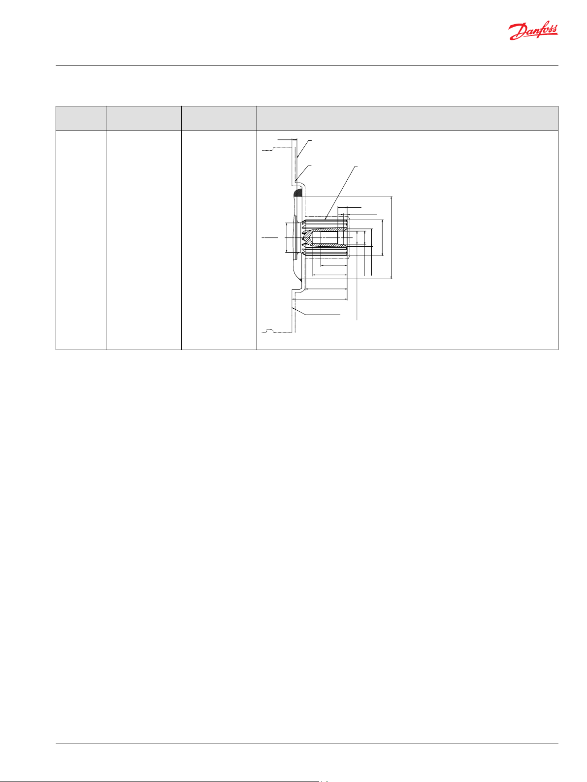
P400514
Spline data
Number of teeth : 17
Pitch friction : 8/16
Pressure angle : 30°
pitch : Ø 53.975
Type of fit : Fillet root side
Per : ANSI B92.1-1996. Class 5
8 ± 0.8
Paint free
Mating coupling must not
Protrude beyond this point
3/4 -10 UNC-2B THD
0
-0.127
15 ± 2
42 ± 2
Full THD
Mounting flange
Flange 165-4
Per SAE J744
6.1 ± 0.5
55 ± 1
Ø131 ±0.1
Ø47 ±0.1
Ø57.15
Ø28 ±0.2
Ø21 ±0.2
66
(88)
0
-0.5
Technical Information
D1 High Power Open Circuit Pumps Size 130/145/193/260
Installation Drawings
Code Description Maximum Torque
Rating
A Splined shaft SAE
J744, 2 1/4 in. 17T,
3621 N•m [32049
lbf•in]
8/16 DP
Drawing
Min. active spline length
(2)
:66 mm [2.60 in]
©
Danfoss | December 2021 BC157786485289en-000501 | 81
Page 82

Mounting flange
Flange 165-4
per SAE J744
Paint free
100
+0.5
0
Key, AS18x11x100
3
+0.1
0
M5 x 0.8
Ø 28 ± 0.2
Ø 60
0
- 0.06
(64)
Ø 131 ± 0.1
Ø 21 ± 0.2
M20 x 2.5-6H THD
42 ± 2
Full THD
55 ± 1
113 ±0.5
105
+ 0.1
0
R1 ± 0.1
6 ± 0.5
15 ± 2
Mating coupling must not
protrude beyond this point
Ø 70
0
- 0.03
Paint free
Mounting flange
Flange 165-4
SAE-E J744 4 bolt
77.7 ± 0.8
(1.5)
Key- SQ, 0.4175 x 3.000, hard
Ø 131 ± 0.1
(49.3)
Ø 44.45
0
- 0.05
Ø 18.1 ± 0.2
Ø 13 ± 0.2
7/16 - 14UNC-2B THD
4.4 ± 0.5
9.5 ± 2
28 ± 2
Full THD
36 ± 1
92
+0.1
0
100 ± 0.5
Mating coupling must not
protrude beyond this point
Ø 70
0
- 0.03
R1.5 ± 0.1
Technical Information
D1 High Power Open Circuit Pumps Size 130/145/193/260
Installation Drawings
Code Description Maximum Torque
Rating
P Straight keyed shaft,
DIN 6885,
2571 N•m [22755
lbf•in]
AS18x11x100
K SAE J744 (D/E)
ø1.75in straight
1787 N•m [15816
lbf•in]
keyed shaft, 0.4375 x
3.000in key
Drawing
82 | © Danfoss | December 2021 BC157786485289en-000501
1) Center bore according to DIN 332 (thread according to DIN 13)
2) Minimum active spline length for the specified torque ratings
Page 83

P400482
145±0.2
72.5±0.1
106.4±0.1
53.2±0.05
145±0.2
72.5±0.1
2xM10x1.5-6H
13 min THD depth
2xM10x1.5-6H
thread through
hole
4xØ17±0.2
6±0.1 depth
through hole
4xØ26±0.2
1.96±0.08
8.1±0.13
53
Ø82.55
+0.065
+0.03
Ø88.621
+0.13
+0
427±2
R0.5
max
15
Paint free
Auxiliary mounting pad
For mating flange 82-2
Per SAE J744(A)
Mounting
flange
O-ring seal required
Ref Ø82.2IDx2.62
cross section
Mating shaft shoulder must
Not protrude beyond this point
Mating shaft top must not
Protrude beyond this point
min
Shaft clearance
min
Shaft clearance
Spline data
Number of teeth :9
Pitch fraction :16/32
Pressure angle :30°
PitchØ :Ø14.288
Type of fit :fillet root side
Per:ANSI B92.1-1996 CLASS 6
P400581
106.4±0.1
53.2±0.05
1.96±0.08
8.1±0.13
56.4
2xM10x1.5-6H
13 min THD depth
Ø82.55
+0.065
+0.03
Ø88.621
+0.13
+0
145±0.2
72.5±0.1
145±0.2
72.5±0.1
4xØ26±0.2
4xØ17±0.2
8±0.1 depth
through hole
427
R0.5
max
15.5
2xM10x1.5-6H
thread through
hole
Paint free
Auxiliary mounting pad
For mating flange 82-2
Per SAE J744(A)
Mounting flange
max
O-ring seal
required
Ref Ø82.2IDx2.62
cross section
Mating shaft shoulder must
Not protrude beyond this point
Mating shaft top must not
Protrude beyond this point
min
Shaft clearance
min
Shaft clearance
Spline data
Number of teeth :13
Pitch fraction :16/32
Pressure angle :30°
PitchØ :Ø20.638
Type of fit :fillet root side
Per :ANSI B92.1-1996 CLASS 6
Technical Information
D1 High Power Open Circuit Pumps Size 130/145/193/260
Installation Drawings
Aux mounting flange
Size 260: Option A1 (SAE-A, 9 teeth)
Specifications
Option Coupling Max torque
A1 5/8 in, 9T, 16/32 DP 205 N•m [1814.40 lbf•in]
Size 260: Option A3 (SAE-A, 13 teeth)
©
Danfoss | December 2021 BC157786485289en-000501 | 83
Specifications
Option Coupling Max torque
A3 7/8 in, 13T, 16/32 DP 619 N•m [5478.61 lbf•in]
Page 84

P400415
4xØ26±0.2
Ø107.823
+0.13
+0
Ø101.6
+0.06
+0.03
R0.5
max
4xM12x1.75-6H
Spline data
Number of teeth : 13
Pitch fraction : 16/32
Pressure angle : 30°
45°±1°
Pitch Ø : Ø20.638
Type of fit : Fillet root side
Per : ANSI B92.1-1996
Class 6
Mating shaft shoulder must
Not protrude beyond this point
Mating shaft top must not
Protrude beyond this point
Shaft clearance
Ø146
15 THD depth
4xØ17
±0.2
6±0.1 depth
through hole
Mounting flange
437±2
72.5±0.05
72.5±0.05
145±0.1
145±0.1
Auxiliary mounting pad
For mating flange 101-2
Per SAE J744(B)
Paint free
1.96±0.08
11.4±0.2
15.6 min
63 min
Shaft clearance
O-ring seal required
Ref Ø94.92IDx2.62cross
section
Ø 146
4x M12x1.75;
16 deep
O-ring seal required
Ref Ø 101.26 ID x 2.62
cross section
Mating shaft shoulder must
not protrude beyond this point
Mating shaft must not
protrude beyond this point
“C” min
shaft clearance
“B” min
shaft clearance
Spline data
Number of teeth: 15
Pitch fraction: 16/32
Pressure angle: 30°
Pitch Ø: 23.813
Type of fit: fillet root side fit
Per: ANSI B92, 1-1006, class 6
Mounting flange
“A” max
Auxiliary mounting pad
For mating flange 101-2
Per SAE J744 (B)
Ø 107.8
+0.13
0
Ø 101.6
+0.06
+0.03
1.96 ± 0.08
Technical Information
D1 High Power Open Circuit Pumps Size 130/145/193/260
Installation Drawings
Size 260: Option B1 (SAE-B, 13 teeth)
Specifications
Option Coupling Max torque
B1 7/8 in, 13T, 16/32 DP 411 N•m [3637.66 lbf•in]
Size 260: Option B2 (SAE-B, 15 teeth)
Legend
Dimension Y3
A 437
B 15.4
C 63
84 | © Danfoss | December 2021 BC157786485289en-000501
Page 85

Ø 146
Ø 107.8
+0.13
0
Ø 101.6
+0.06
+0.03
O-ring seal required
Ref Ø 101.26 ID x 2.62
cross section
Spline data
Number of teeth: 13
Pitch fraction: 16/32
Pressure angle: 30
Pitch Ø: 20.638
Type of fit: fillet root side fit
Per: ANSI B92, 1-1996, class 6
Mounting flange
“A” max
Auxiliary mounting pad
For mating flange 101-2
Per SAE J744 (B)
1.96 ± 0.08
“B” min
shaft clearance
“C” min
shaft clearance
Mating shaft shoulder must
not protrude beyond this point
Mating shaft must not
protrude beyond this point
Technical Information
D1 High Power Open Circuit Pumps Size 130/145/193/260
Installation Drawings
Specifications
Option Coupling Max torque
B2 1in, 15T, 16/32DP Pending
Size 260: Option BA (SAE-B, 13 teeth)
Legend
Dimension Value
A 437
B 15.4
C 63
Specifications
Option Coupling Max torque
BA 7/8in, 13T, 16/32DP 411 N•m [3637.66 lbf•in]
©
Danfoss | December 2021 BC157786485289en-000501 | 85
Page 86

Ø 146
4x M12x1.75;
16 deep
Auxiliary mounting pad
For mating flange 101-2
Per SAE J744 (B)
Ø107.8
+0.13
0
Ø101.6
+0.06
+0.03
B min
shaft clearance
C min
shaft clearance
Mating shaft must not
protrude beypnd this point
Mating shaft shoulder must
not protrude beyond this point
Spline data
Number of teeth: 13
Pressure angle: 30
Pitch Ø: 20.638
Type of fit: fillet root side fit
Per: ANSI B92, 1-1996, class 6
Mounting flange
A max
2 ± 0.08
Technical Information
D1 High Power Open Circuit Pumps Size 130/145/193/260
Installation Drawings
Size 260: Option BB (SAE-B, 13 teeth)
Legend
Dimension Value
A 437
B 15.4
C 62.25
Specifications
Option Coupling Max torque
BB 7/8in, 13T, 16/32DP 411 N•m [3637.66 lbf•in]
86 | © Danfoss | December 2021 BC157786485289en-000501
Page 87

P400483
19 min THD
depth
R0.5
max
Paint free
Auxiliary mounting pad
For mating flange 127-4
Per SAE J744(C)
Mounting
flange
O-ring seal required
Ref Ø120.32IDx2.62
cross section
Mating shaft shoulder must
Not protrude beyond this point
Mating shaft top must not
Protrude beyond this point
min
Shaft clearance
Spline data
Number of teeth:14
Pitch fraction :12/24
Pressure angle :30°
PitchØ :Ø29.633
Type of fit :fillet root side
Per :
ANSI B92.1-1996 CLASS 6
Ø134.1
+0.13
0
Ø127
+0.07
+0.03
433±2
1.96±0.08
11
59
15±0.1
4xØ26±0.2
4xØ17±0.2
2xM16x2-6H
4xM12x1.75-6H
145±0.2
72.5±0.1
145±0.2
72.5±0.1
181±0.2
90.5±0.1
114.5±0.2
57.2
±0.1
114.5±0.2
57.3±0.1
11.5±0.2 depth
counter bore
19 min THD depth
min
Shaft clearance
Technical Information
D1 High Power Open Circuit Pumps Size 130/145/193/260
Installation Drawings
Size 260: Option C5 (SAE-C, 14 teeth)
Specifications
Option Coupling Max torque
C5 1 1/4 in, 14T, 12/24 DP 1638 N•m [14497.52 lbf•in]
©
Danfoss | December 2021 BC157786485289en-000501 | 87
Page 88

P400582
19 min THD
depth
R0.5
max
Paint free
Auxiliary mounting pad
For mating flange 127-4
Per SAE J744(C)
Mounting flange
max
O-ring seal
required
Ref Ø120.32IDx2.62
cross section
Mating shaft shoulder must
Not protrude beyond this point
Mating shaft top must not
Protrude beyond this point
min
Shaft clearance
Spline data
Number of teeth
:
:
:
:
:
:
14
Pitch fraction 12/24
Pressure angle 30°
PitchØ Ø29.633
Type of fit fillet root side
Per ANSI B92.1-1996
CLASS 6
Ø134.1
+0.13
0
Ø127
+0.07
+0.03
457
1.96±0.08
39.3
80.1
15±0.1
4xØ26±0.2
4xØ17±0.2
2xM16x2-6H
4xM12x1.75-6H
145±0.2
72.5±0.1
145±0.2
72.5±0.1
181±0.2
90.5±0.1
114.5±0.2
57.2±0.1
114.5±0.2
57.3±0.1
10.5±0.2 depth
counter bore
19 min THD depth
min
Shaft clearance
P400583
83.2
1.96±0.08
42.3
15±0.1
460
161.6±0.1
80.8±0.05
161.6±0.1
80.8±0.05
Ø158.4±0.05
Ø152.4
+0.07
+0.03
R0.5
max
Paint free
4xM20x2.5-6H
28 min THD depth
Auxiliary mounting pad
For mating flange 152-4
Per SAE J744(D)
Mounting flange
max
O-ring seal
required
Ref Ø145.72IDx2.62
cross section
Mating shaft shoulder must
Not protrude beyond this point
Mating shaft top must not
Protrude beyond this point
min
min
Shaft clearance
Shaft clearance
Spline data
Number of teeth :
:
:
:
:
:
13
Pitch fraction 8/ 16
Pressure angle 30°
PitchØ Ø41.275
Type of fit fillet root side
Per ANSI B92.1-1996
CLASS 6
Technical Information
D1 High Power Open Circuit Pumps Size 130/145/193/260
Installation Drawings
Size 260: Option C9 (SAE-C, 13 teeth)
Specifications
Option Coupling Max torque
C9 1 3/4 in, 13T, 8/16 DP 1891 N•m [16736.76 lbf•in]
Size 260: Option D2 (SAE-D, 13 teeth)
88 | © Danfoss | December 2021 BC157786485289en-000501
Specifications
Option Coupling Max torque
D2 1 3/4 in, 13T, 8/16 DP 1819 N•m [16099.50 lbf•in]
Page 89

P400416
Mounting
flange
Spline data
Number of teeth : 24
Modules : 2
Pressure angle : 30°
Pitch Ø : Ø48
Type of fit :
Flat root side
Per : DIN 5480
Class 9H
Mating shaft shoulder must
Not protrude beyond this point
Mating shaft top must not
Protrude beyond this point
Shaft clearance
35 min
70.5 min
Shaft clearance
1.96±0.08
161.6±0.1
80.8±0.05
161.6±0.1
80.8±0.05
15±0.1
O-ring seal required
Ref Ø145.72IDx2.62cross
section
Ø158.4±0.05
Ø152.4
+0.07
-0.03
R0.5
max
460±2
Auxiliary mounting pad
For mating flange 152-4
Per SAE J744(D)
Paint free
4xM20x2.5-6H
23 THD depth
P400484
15 min THD depth
R0.5
max
Paint free
Auxiliary mounting pad
For mating flange 165-4
Per SAE J744(E)
Mounting
flange
O-ring seal required
Ref Ø158.42IDx2.62
cross section
Mating shaft shoulder must
Not protrude beyond this point
Mating shaft top must not
Protrude beyond this point
min
Shaft clearance
Spline data
Number of teeth:24
Module :2
Pressure angle :30°
PitchØ :Ø48
Type of fit :fillet root side
Per:DIN 5480 CLASS 9H
20±0.2 depth
counter bore
145±0.2
72.5±0.1
145±0.2
72.5±0.1
224.5±0.2
122.25±0.1
224.5±0.2
112.25±0.1
442±2
1.96±0.08
17
19±0.2
Ø165.1±0.05
Ø170.99±0.12
4x M20x 2.5-6H
4xØ26±0.2
4xØ17±0.2
68
min
Shaft clearance
Technical Information
D1 High Power Open Circuit Pumps Size 130/145/193/260
Installation Drawings
Size 260: Option D5 (SAE-D, 24 teeth)
Specifications
Option Coupling Max torque
D5 N50 x 2 x 30 x 24 x 9H 1936 N•m [17135.04 lbf•in]
Size 260: Option E2 (SAE-E, 24 teeth)
©
Danfoss | December 2021 BC157786485289en-000501 | 89
Specifications
Option Coupling Max torque
E2 N50 x 2 x 30 x 24 x 9H 1936 N•m [17135.04 lbf•in]
Page 90

P400417
26 THD depth
R0.5
max
Paint free
Auxiliary mounting pad
For mating flange 165-4
Per SAE J744(E)
Mounting
flange
±2
O-ring seal required
Ref Ø158.42IDx2.62
cross section
Mating shaft shoulder must
Not protrude beyond this point
Mating shaft top must not
Protrude beyond this point
min
Shaft clearance
Spline data
Number of teeth:
:
:
:
:
:
28
Module 2
Pressure angle 30°
PitchØ Ø56
Type of fit
Flat root side
Per DIN 5480
CLASS 9H
20±0.2 depth
counter bore
145±0.2
72.5±0.1
145±0.2
72.5±0.1
224.5±0.2
122.25±0.1
224.5±0.2
112.25±0.1
442
1.96±0.08
16
19±0.2
Ø165.1
Ø170.99±0.12
4x M20x 2.5-6H
4xØ26±0.2
4xØ17±0.2
68
min
Shaft clearance
-0.03
+0.07
Technical Information
D1 High Power Open Circuit Pumps Size 130/145/193/260
Installation Drawings
Size 260: Option E3 (SAE-E, 28 teeth)
Specifications
Option Coupling Max torque
E3 N60 x 2 x 30 x 28 x 9H 1936 N•m [17135.04 lbf•in]
Before finalizing your design, please request a certified drawing.
90 | © Danfoss | December 2021 BC157786485289en-000501
Page 91

Technical Information
D1 High Power Open Circuit Pumps Size 130/145/193/260
Installation Drawings
Inlet pressure gauge port
An inlet pressure gauge port is offered in certain porting configurations. Pump configurations with this
additional port are indicated in the table below.
Displacement Porting Option Inlet pressure gauge port
D1P145 CW w/o impeller No
CCW w/o impeller Yes
D1P193 CW w/o impeller Yes
CCW w/ impeller No
D1P260 CW w/ impeller No
CCW w/ impeller Yes
Inlet pressure gauge port general location
w/ impeller Yes
w/ impeller Yes
w/ impeller Yes
©
Danfoss | December 2021 BC157786485289en-000501 | 91
Page 92

Servo pressure gauge port M4
DIN 3852 M12x1.5;
12.5 full thread depth
30 ± 0.5110 ± 0.8
Suction pressure gauge port M5
DIN 3852 M12x1.5;
12.5 full thread depth
314.5 ± 1.2
363 ± 1.2
60 ± 0.8
Drain port L3
DIN 3852 M33x2;
22 full thread depth
Lifting hole
DIN 13 M12x1.75;
10 full thread depth
Max displacement limiter
Technical Information
D1 High Power Open Circuit Pumps Size 130/145/193/260
Installation Drawings
D1P 260 CCW + Inlet pressure gauge port
Port Description Standard Size Max. Pressure
(bar [psi])
M5 Measurement
DIN 3852 M12 x 1.5 100 [1450] X
point, suction
pressure
State
92 | © Danfoss | December 2021 BC157786485289en-000501
Page 93

Technical Information
D1 High Power Open Circuit Pumps Size 130/145/193/260
Additional Information
D1P tandem with Danfoss pumps
1st Pump 2nd Pump
D1P (OC)
Through Drive
Flange Coupling Code Size (shaft) Size (shaft) Size (shaft) Size (shaft) Size (shaft) Size (shaft) Size (shaft)
82-2
A
101-2
B
127-2&4
C
152-4
D
165-4
E
165-4
E
5/8 in
9T
7/8 in
13T
1 1/4 in
14T
1 3/4 in
13T
W50 D5
1 3/4 in
13T
W50 E2
W60 E3
A1
A3
B1
C5
C9
D2
D1P (OC) S45 (OC) S90 (CC) H1P (CC) S42 (CC) S40 (CC) Gear Pump
4 ~ 45
(SA, SM, SE)
7 ~ 45
130/145
(T)
193
(T)
260
(T)
25, 30, 38, 45
(C2)
45, 51, 60, 65, 74,
75, 90, 100, 130,
147
(S1)
100, 130, 147
(S4)
55, 75, 100
(S1)
130
(F1)
45, 53
(G4)
60, 68, 69, 78,
89, 100
(G1)
115, 130, 147,
165
(G3)
28, 32, 41, 51
(C)
25, 35, 44, 46
(A)
7 ~ 90
(SA, SL, SH)
22 ~ 200
(RA, RD, S0)
(SH)
D1P tandem pump torque
Maximum torque rating and tandem pump torque
D1 Pump Displacement 130/145 193 260
Torque at Vg max and Δp = 350 bar 724/808 N•m
[6407.94/7151.40 lbf•in]
Max torque rating of input shaft T 3100 N•m [27437 lbf•in] 3100 N•m [27437 lbf•in] 5432 N•m [48077 lbf•in]
S 1528 N•m [13524 lbf•in] 1536 N•m [13595 lbf•in] 1535 N•m [13586 lbf•in]
A - 2422 N•m [21437 lbf•in] 3621 N•m [32049 lbf•in]
P 1411 N•m [12488 lbf•in] 2195 N•m [19427 lbf•in] 2571 N•m [22755 lbf•in]
K 1787 N•m [15816 lbf•in] 1787 N•m [15816 lbf•in] 1787 N•m [15816 lbf•in]
1075 N•m [9514.55
lbf•in]
1448 N•m [12815.88
lbf•in]
©
Danfoss | December 2021 BC157786485289en-000501 | 93
Page 94

Technical Information
D1 High Power Open Circuit Pumps Size 130/145/193/260
Additional Information
Maximum torque rating and tandem pump torque (continued)
D1 Pump Displacement 130/145 193 260
Max torque rating of different aux mounting
flange options
A1 205 N•m [1814.40
lbf•in]
A2 Pending - A3 - 619 N•m [5478.61
B1 411 N•m [3637.66
lbf•in]
B2 Pending Pending Pending
BA 411 N•m [3637.66
lbf•in]
BB 411 N•m [3637.66
lbf•in]
C5 1164 N•m [10302.27
lbf•in]
C9 - 1790 N•m [15842.83
D2 1130 N•m [10001.35
lbf•in]
D5 1164 N•m [10302.27
lbf•in]
E2 - 1790 N•m [15842.83
E3 - - 1936 N•m [17135.04
205 N•m [1814.40
lbf•in]
lbf•in]
411 N•m [3637.66
lbf•in]
411 N•m [3637.66
lbf•in]
411 N•m [3637.66
lbf•in]
1289 N•m [11408.61
lbf•in]
lbf•in]
1630 N•m [14426.72
lbf•in]
1790 N•m [15842.83
lbf•in]
lbf•in]
205 N•m [1814.40
lbf•in]
619 N•m [5478.61
lbf•in]
411 N•m [3637.66
lbf•in]
411 N•m [3637.66
lbf•in]
411 N•m [3637.66
lbf•in]
1638 N•m [14497.52
lbf•in]
1891 N•m [16736.76
lbf•in]
819 N•m [16099.51
lbf•in]
1936 N•m [17135.04
lbf•in]
1936 N•m [17135.04
lbf•in]
lbf•in]
D1P tightening torque
The following tightening torques apply:
Fittings Observe the manufacturer’s instruction regarding the tightening torques of the
fittings used.
Fixing screws For fixing screws according to DIN 13, we recommend checking the tightening torque
individually according to VDI 2230.
Locking screws For the metal locking screws supplied with the D1 pump, the required torques are as
indicated in the table below:
Thread size Standard Required torque Wrench size
M12 x 1.5
M14 x 1.5 34 N•m [300.93 lbf•in] 6 mm
M26 x 1.5 60 N•m [531.05 lbf•in] 12 mm
M33 x 2 225 N•m [1991.42 lbf•in] 17 mm
DIN 3852
25 N•m [221.27 lbf•in] 6 mm
94 | © Danfoss | December 2021 BC157786485289en-000501
Page 95

L1
L2
L3
S
200mm min 200mm min
200mm min
100mm min
200mm min
100mm min
200mm min
200mm min
200mm min
100mm min
200mm min
100mm min
P400089
1
L1
L2
L3
S
2
L1
L2
L3
S
3
L1
L2
L3
S
4
Technical Information
D1 High Power Open Circuit Pumps Size 130/145/193/260
Installation Notes
D1P below-reservoir (standard)
Recommended arrangements : 1 and 2.
Fill pump case with clean oil before start
Suction (absolute) : P min = 0.6 bar with charge pump (0.8 bar without charge pump), P max = 2 bar. Do
not restrict suction line
Drain (absolute) : P max = 2 bar. Do not restrict drain line, do not combine drain line
Arrangements Air Bleeding Filling
1 L1 S + L1
2 L3 S + L2
3 L1 / L2 S + L1 / L2
4 L3 S + L1 / L2
©
Danfoss | December 2021 BC157786485289en-000501 | 95
Page 96

L1
L2
L3
S
200mm min
100mm min
200mm min
5
V2
V1
800mm max
L2
L1
L3
S
200mm min
6
V2
V1
800mm max
200mm min
100mm min
L2
L1
L3
S
200mm min
100mm min
P400090
200mm min
7
V2
V1
800mm max
0.5bar
Technical Information
D1 High Power Open Circuit Pumps Size 130/145/193/260
Installation Notes
D1P above-reservoir
Fill pump case with clean oil before start
Suction (absolute) : P min = 0.6 bar with charge pump (0.8 bar without charge pump), P max = 2 bar. Do
not restrict suction line
Drain (absolute) : P max = 2 bar. Do not restrict drain line, do not combine drain line
Arrangements Air Bleeding Filling
5 V1 + V2 V2 (S) + V1 (L1)
6 L3 + V2 V2 (S) + V1 (L2)
7 V1 + V2 V2 (S) + V1 (L1 / L2)
Caution! Installation hazards!
Failure to adhere to the installation notes may result in shortened product life.
The maximum allowable suction height is 0.8m. The allowable suction height is derived from the total
pressure loss.
The D1 pump with charge pump is not designed for above-Reservoir installation.
For control options with pressure controllers, proportional displacement control, the minimum
displacement setting must be Vg ≥ 5% Vg max.
Recommendation for arrangement 7 (shaft upwards): A check valve in the case drain line (cracking
pressure 0.5 bar) can prevent draining of the case interior.
96 | © Danfoss | December 2021 BC157786485289en-000501
Page 97

8
9
10
L1
L2
L3
S
L1
L2
L3
S
L1
L2
L3
S
100mm min
200mm min
200mm min
100mm min
100mm min
P400091
200mm min
200mm min
200mm min
200mm min
Technical Information
D1 High Power Open Circuit Pumps Size 130/145/193/260
Installation Notes
D1P reservoir installation
Fill pump case with clean oil before start
Suction (absolute) : P min = 0.6 bar with charge pump (0.8 bar without charge pump), P max = 2 bar. Do
not restrict suction line
Drain (absolute) : P max = 2 bar. Do not restrict drain line, do not combine drain line
Arrangements Air Bleeding Filling
8 L1 Automatically via all open L1, L2, L3
9 L3
10 L3
•
It is recommended to fit a pipe to the suction port S and fitting a pipe to case drain port L1, L2 or L3
and S ports through position below
the hydraulic fluid level.
(See arrangements), the other case drain ports must be plugged in this situation. The pump should be
filled before fitting the pipe and filling the tank with hydraulic fluid.
•
It is only permissible to install a pump with solenoids (E.g. a pump with electric displacement control)
at tank-level, if used hydraulic fluids are based on mineral oil and the oil temperature in the tank does
not exceed 80° C.
©
Danfoss | December 2021 BC157786485289en-000501 | 97
Page 98

P400281
Maximum
displacement
limiter
Minimum
displacement
limiter
Technical Information
D1 High Power Open Circuit Pumps Size 130/145/193/260
Displacement Limiter
D1P displacement limiter
Series D1 pumps feature maximum and minimum displacement limiters, which limit displacement
mechanically.
Maximum Displacement Limiter
Frame Setting range Displacement change per turn
130
145
193
260
Minimum Displacement Limiter
Frame Setting range Displacement change per turn
130
145
193
260
72 cm3 – 130 cm
72 cm3 – 145 cm
0 cm3 – 193 cm
56 cm3 – 260 cm
0 cm3 – 124 cm
0 cm3 – 124 cm
0 cm3 – 193 cm
0 cm3 – 260 cm
3
3
3
3
3
3
3
3
11 cm3/rev
11 cm3/rev
16 cm3/rev
19 cm3/rev
9 cm3/rev
9 cm3/rev
15 cm3/rev
18 cm3/rev
Displacement Limiter Cross-Section View
98 | © Danfoss | December 2021 BC157786485289en-000501
Page 99

Danfoss
Power Solutions GmbH & Co. OHG
Krokamp 35
D-24539 Neumünster, Germany
Phone: +49 4321 871 0
Danfoss
Power Solutions ApS
Nordborgvej 81
DK-6430 Nordborg, Denmark
Phone: +45 7488 2222
Danfoss
Power Solutions (US) Company
2800 East 13th Street
Ames, IA 50010, USA
Phone: +1 515 239 6000
Danfoss
Power Solutions Trading
(Shanghai) Co., Ltd.
Building #22, No. 1000 Jin Hai Rd
Jin Qiao, Pudong New District
Shanghai, China 201206
Phone: +86 21 2080 6201
Products we offer:
Hydro-Gear
www.hydro-gear.com
Daikin-Sauer-Danfoss
www.daikin-sauer-danfoss.com
Cartridge valves
•
DCV directional control
•
valves
Electric converters
•
Electric machines
•
Electric motors
•
Gear motors
•
Gear pumps
•
Hydraulic integrated
•
circuits (HICs)
Hydrostatic motors
•
Hydrostatic pumps
•
Orbital motors
•
PLUS+1® controllers
•
PLUS+1® displays
•
PLUS+1® joysticks and
•
pedals
PLUS+1® operator
•
interfaces
PLUS+1® sensors
•
PLUS+1® software
•
PLUS+1® software services,
•
support and training
Position controls and
•
sensors
PVG proportional valves
•
Steering components and
•
systems
Telematics
•
Danfoss Power Solutions is a global manufacturer and supplier of high-quality hydraulic and
electric components. We specialize in providing state-of-the-art technology and solutions
that excel in the harsh operating conditions of the mobile off-highway market as well as the
marine sector. Building on our extensive applications expertise, we work closely with you to
ensure exceptional performance for a broad range of applications. We help you and other
customers around the world speed up system development, reduce costs and bring vehicles
and vessels to market faster.
Danfoss Power Solutions – your strongest partner in mobile hydraulics and mobile
electrification.
Go to www.danfoss.com for further product information.
We offer you expert worldwide support for ensuring the best possible solutions for
outstanding performance. And with an extensive network of Global Service Partners, we also
provide you with comprehensive global service for all of our components.
Local address:
Danfoss can accept no responsibility for possible errors in catalogues, brochures and other printed material. Danfoss reserves the right to alter its products without notice. This also applies to products
already on order provided that such alterations can be made without subsequent changes being necessary in specifications already agreed.
All trademarks in this material are property of the respective companies. Danfoss and the Danfoss logotype are trademarks of Danfoss A/S. All rights reserved.
©
Danfoss | December 2021 BC157786485289en-000501
 Loading...