

Page 1
Parts Manual
D1 High Power Open Circuit Pumps
Size 260
www.danfoss.com
Page 2
Parts Manual
D1P size 260
Revision history Table of revisions
Date Changed Rev
December 2021 Added new controls corrected part numbers, added SB-2020-042 0501
February 2021 Updated part numbers 0407
September 2020 Corrected control service kit part numbers 0406
March 2020 Corrected part numbers and changed document number from AX00000311 0405
January 2020 Added new part options 0304
April 2019 Updated various part numbers and added new options 0303
June 2018 Updated for global launch 0301
March 2017 Minor updates 0202
January 2017 Split each frame size into its own document 0201
June 2016 Added size 260 0104
April 2016 Updated document format 0103
July 2015 Minor updates 0102
January 2015 First edition 0101
2 | © Danfoss | December 2021 AX218086484736en-000501
Page 3

Parts Manual
D1P size 260
Contents
General information
Controls
Input shaft
Mounting flange
Endcap
Auxiliary mounting flange
Special hardware
Overhaul seal kit
Service bulletins
Service Parts Identification............................................................................................................................................................4
Nameplate...........................................................................................................................................................................................4
Date code............................................................................................................................................................................................ 5
About service bulletins...................................................................................................................................................................5
Procedure to identify a part..........................................................................................................................................................5
Adobe Acrobat 2-page viewing..................................................................................................................................................6
Order code.......................................................................................................................................................................................... 7
Control ENSN......................................................................................................................................................................................8
D1P control NPNR..........................................................................................................................................................................10
Control NPNN..................................................................................................................................................................................12
Control NPSN...................................................................................................................................................................................14
Control TPSN....................................................................................................................................................................................16
Control NNES...................................................................................................................................................................................18
Control TPE2.................................................................................................................................................................................... 20
Control NPE0....................................................................................................................................................................................22
Control NPE2....................................................................................................................................................................................24
Shaft A-T............................................................................................................................................................................................26
Shaft K................................................................................................................................................................................................ 28
Mounting flange E4.......................................................................................................................................................................30
Mounting flange EA...................................................................................................................................................................... 32
Endcap Y3......................................................................................................................................................................................... 34
Aux mounting A1, A3................................................................................................................................................................... 36
Aux mounting B1, B2, BA, BB..................................................................................................................................................... 38
Aux mounting C5, C9....................................................................................................................................................................40
Aux mounting D2, D5, E2............................................................................................................................................................42
Aux mounting E3........................................................................................................................................................................... 44
Aux mounting NN..........................................................................................................................................................................46
Special hardware NNN................................................................................................................................................................. 48
Orifice NNN, NNF............................................................................................................................................................................50
D1P 260 seal kit...............................................................................................................................................................................52
SB-2020-042.....................................................................................................................................................................................53
©
Danfoss | December 2021 AX218086484736en-000501 | 3
Page 4
Parts Manual
D1P size 260
General information
Service Parts Identification
Nameplate
The following information and procedure is used to identify the module group, item number,
manufacture date, part number, and part name of the parts included in the D1P 260.
The parts listed include all parts which may be used when performing either “Minor Repairs”, “Major
Repairs” or “Conversions” on the .
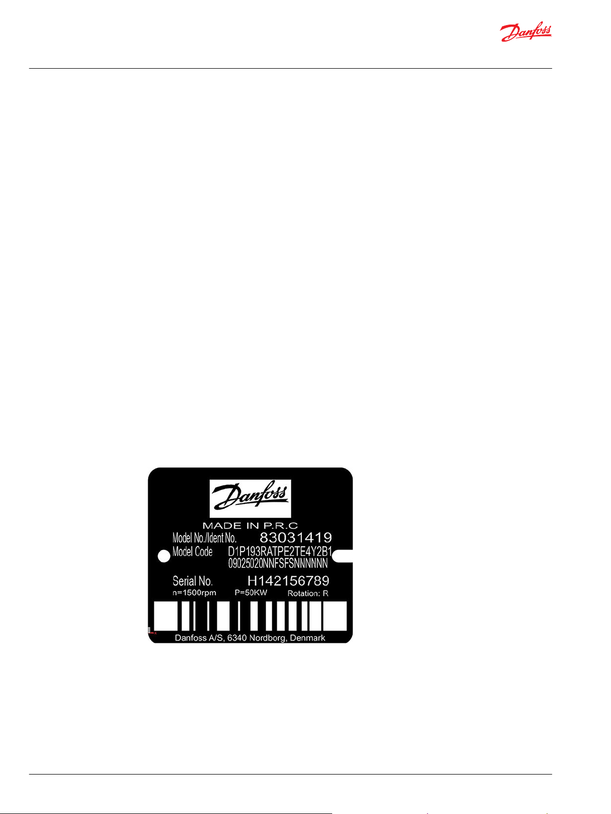
Each unit will have a nameplate affixed to the housing. The nameplate will include the following
information:
Model Code
The Danfoss model code completely defines the specific unit and must be used when ordering parts to
service this product.
Model Number
The Danfoss model number is used by the factory in manufacturing. On repeat orders, a complete unit
can be ordered by the model number.
Serial Number
The Danfoss serial number is used to identify the manufacture date and the unit sequence in the build.
The serial number is also used to identify the units warranty time period.
The letter code indicates the location of original manufacture (assembly).
The first number (2 digits) indicates the year of manufacture. The second number (2 digits) indicates the
calendar week of manufacture.
The third number (5 digits) is a sequential number used to identify a specific unit.
4 | © Danfoss | December 2021 AX218086484736en-000501
Page 5
Parts Manual
D1P size 260
General information
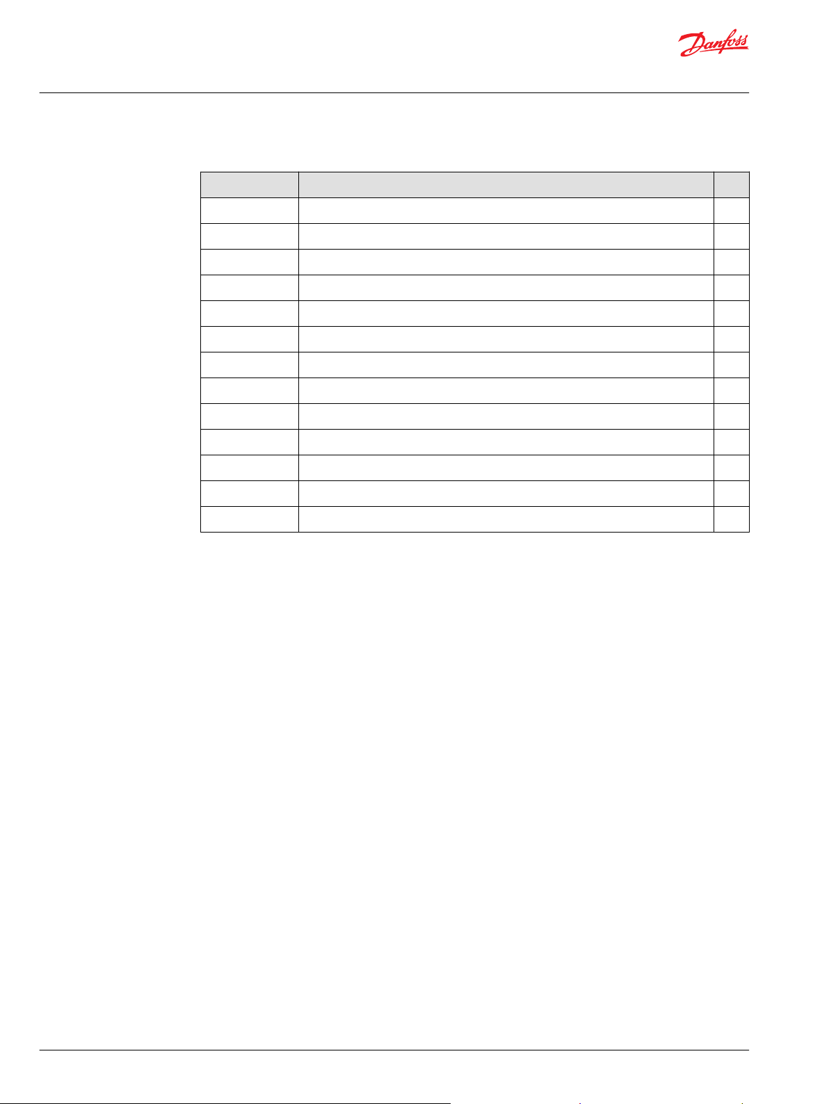
Date code
About service bulletins
The date code is defined as the year and week of manufacture. The same item number may list more than
one part number. This indicates that there is more than one configuration for that item number. You will
see that there are different date codes for the different part numbers. Find the date code of your unit
from the nameplate to determine which service part number you need to order.
Example: The service part desired is item G30
Order Code Item Date Begin Date End Part Number Part Name Qty. per
80 G30 89-17 8000243 End cap gasket 1
G30 89-16 8000151 End cap gasket
(SB-1995-006)
Model/Kit
1
All units using this order code with a date code prior to 89-17 must use part number “8000151.” All units
with a date code of 89-17 and newer must use part number “8000243.”
A Service Bulletin Number (SB-_ _ _ _ - _ _ _) may follow the “Part Name” of the part you desire. You must
read that Service Bulletin prior to ordering that part. The information contained in these Service Bulletins,
as of the print date of this bulletin, are included at the end of this manual. Service Bulletins contain more
detailed information such as interchangeability, what additional parts are involved, etc. It is suggested
that you add additional Service Bulletins to this manual as you receive them.
Procedure to identify a part
The modular design of this product results in a simplified service parts list and part number identification
procedure.
The same item numbers are used for same part names on all units within a product type. A part number
that has another number following it in parentheses is done to make this a world wide manual.
©
Danfoss | December 2021 AX218086484736en-000501 | 5
Page 6
Parts Manual
D1P size 260
General information
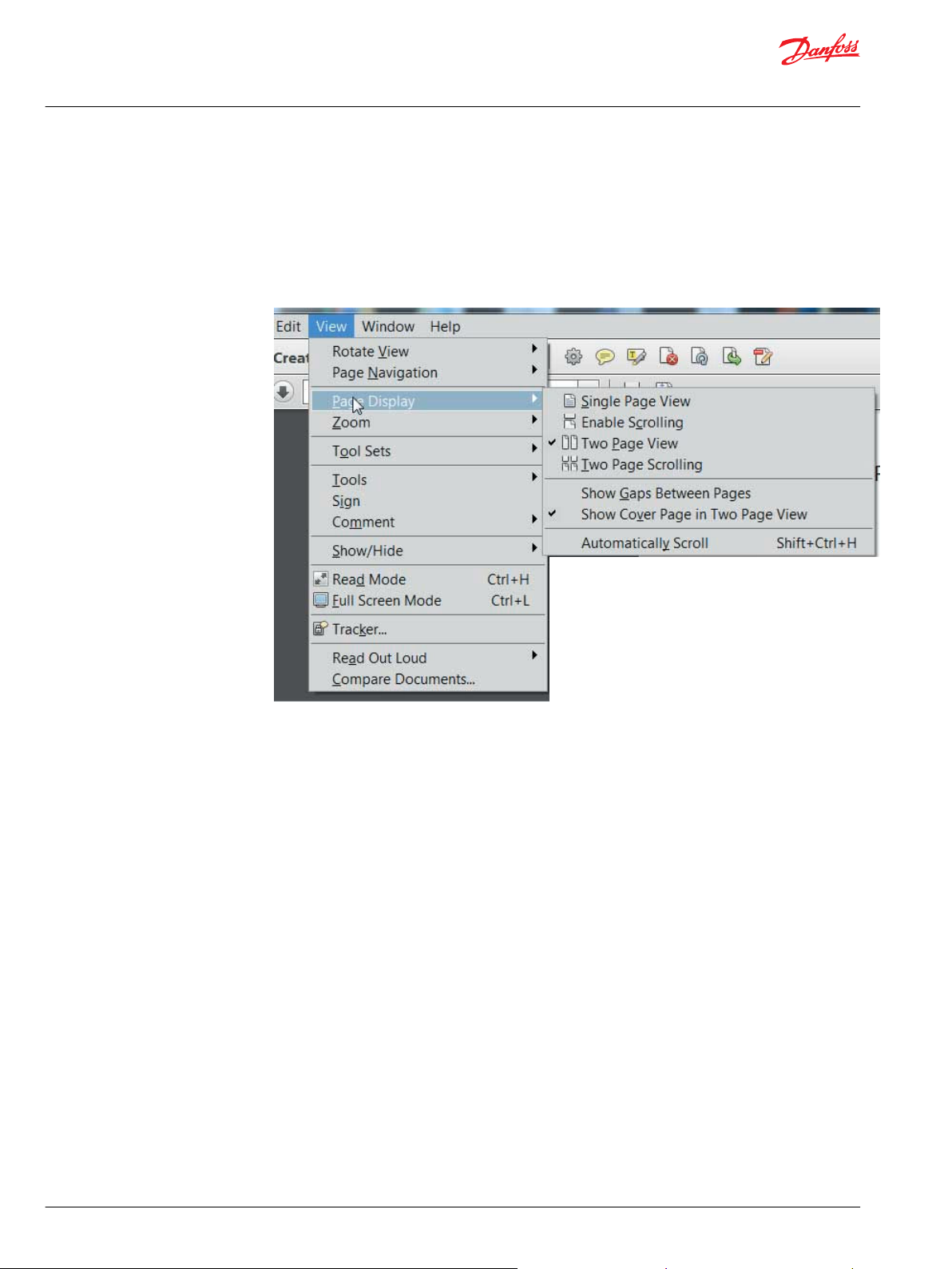
Adobe Acrobat 2-page viewing
While viewing manual in Adobe Acrobat, the following settings need to be applied to ensure proper
page display.
1. Select “View” → “Page Display” → “Two Page View”
2. Select “View” → “Page Display” → “Show Cover Page in Two Page View”
6 | © Danfoss | December 2021 AX218086484736en-000501
Page 7
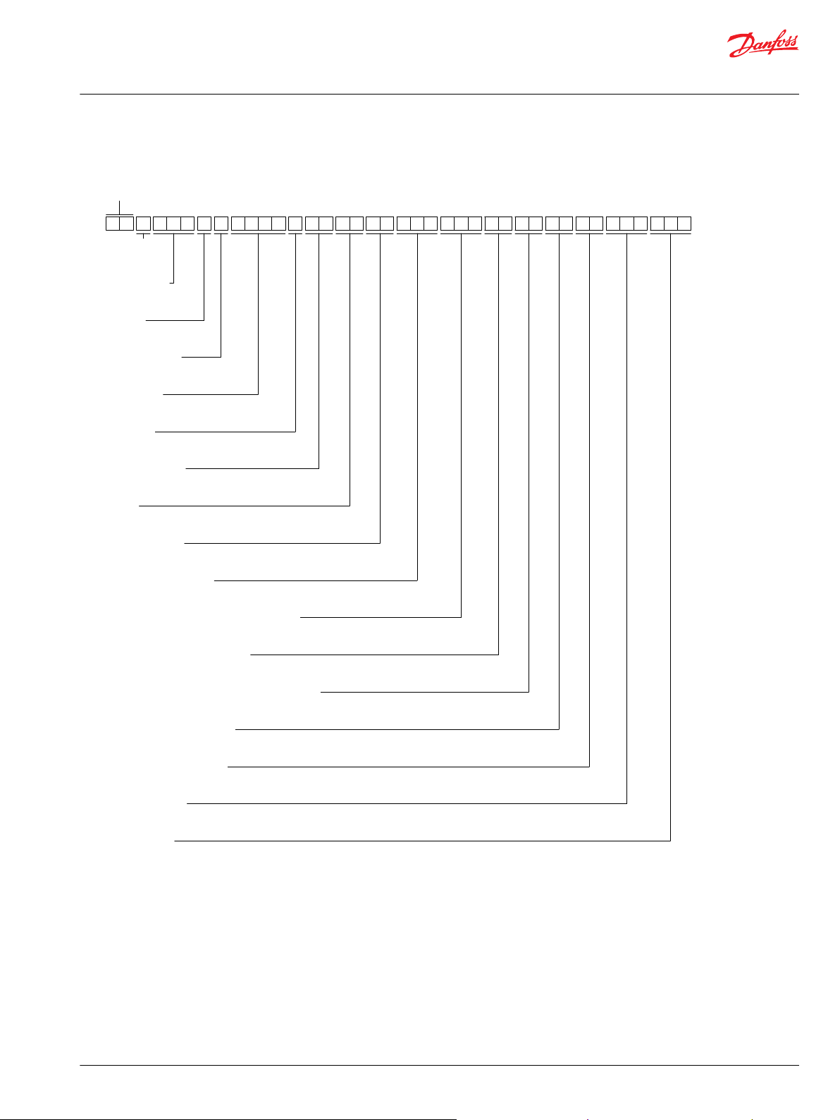
D 1 P 2 6 0 R A T P E 2 T E 4 Y 3 B 1 1 1 5 3 4 0 N N N N F S 0 5 N N N NN N
Series
Product
type
Displacement
A B C D E F G H J K L M N P R S
Rotation
Product version
Control type
Input shaft
Endcap
Power control setting
Pressure compensated control setting
Load sensing control setting
Hydraulic disp control start pressure setting
Max displacement setting
Min displacement setting
Special hardware
Special feature
Mounting flange
Auxiliary flange
Parts Manual
D1P size 260
General information
Order code
©
Danfoss | December 2021 AX218086484736en-000501 | 7
Page 8
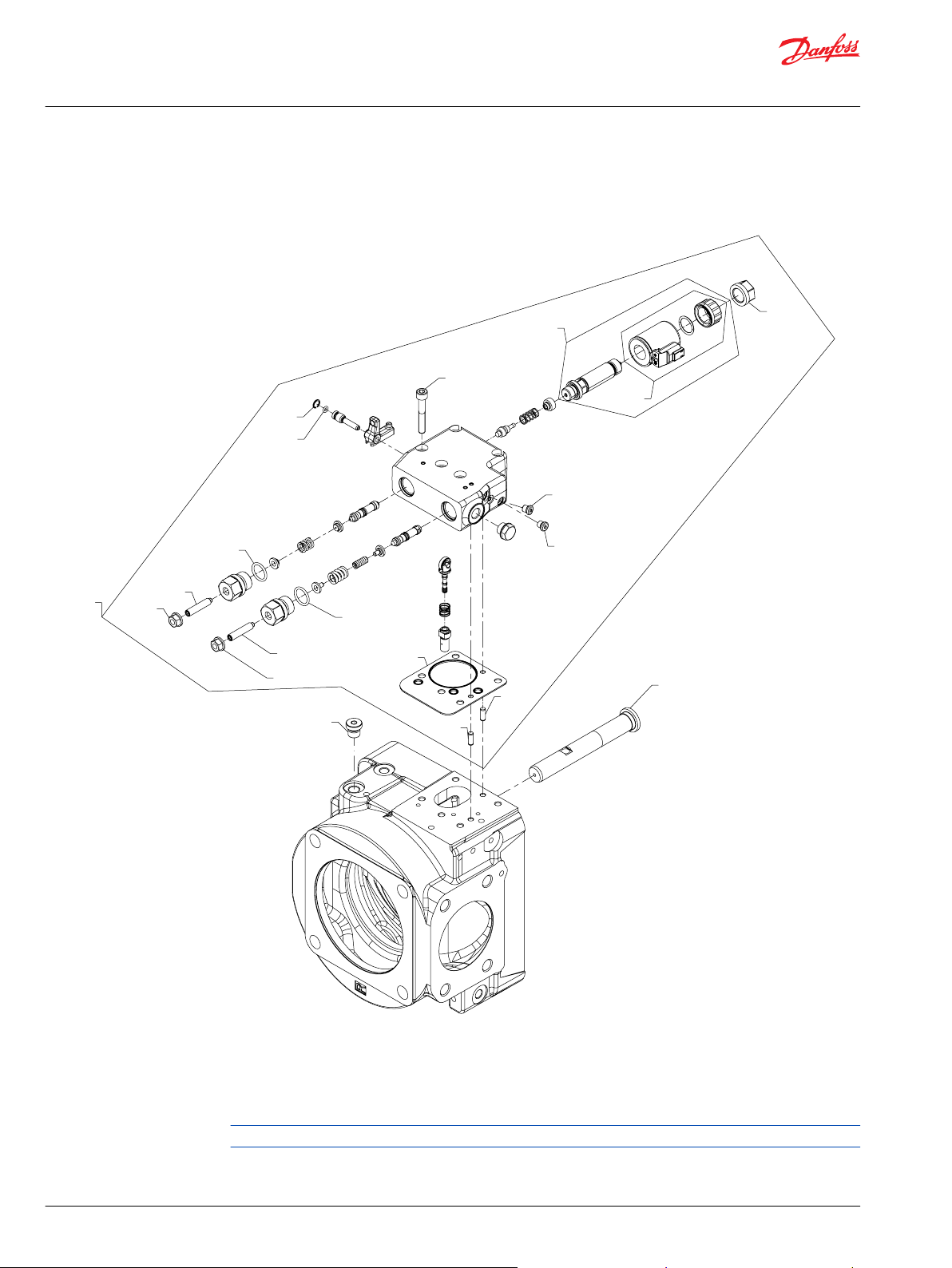
QD01
*D480
D470
*D450
D870
*D880
D900
*D850
*D145
D160
D160
A220
D135
D104
3x
D175
D700
QD701
D705
D550
*D540
Parts Manual
D1P size 260
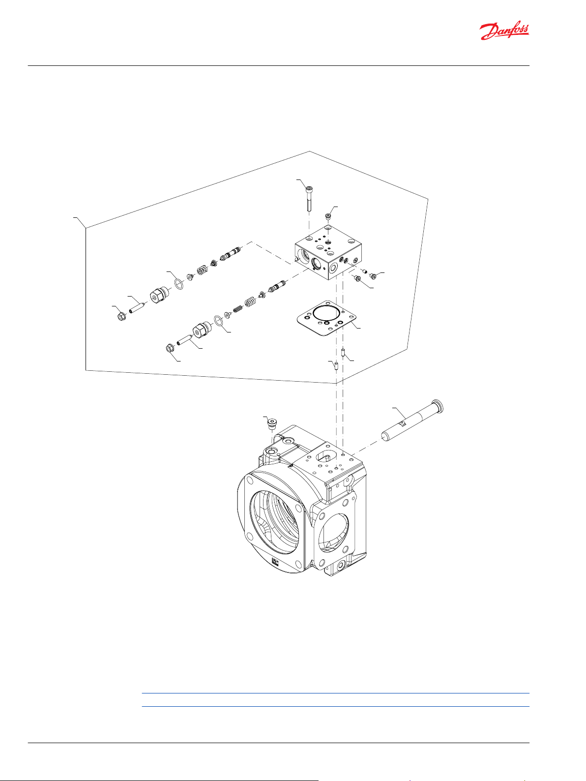
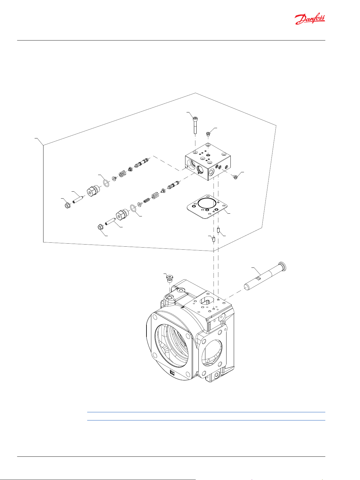
Controls
D1P ENSN control
Parts configuration
* Included in overhaul seal kit Q210
Generic endcap used to show part location only.
8 | © Danfoss | December 2021 AX218086484736en-000501
Page 9
Parts Manual
D1P size 260
Controls
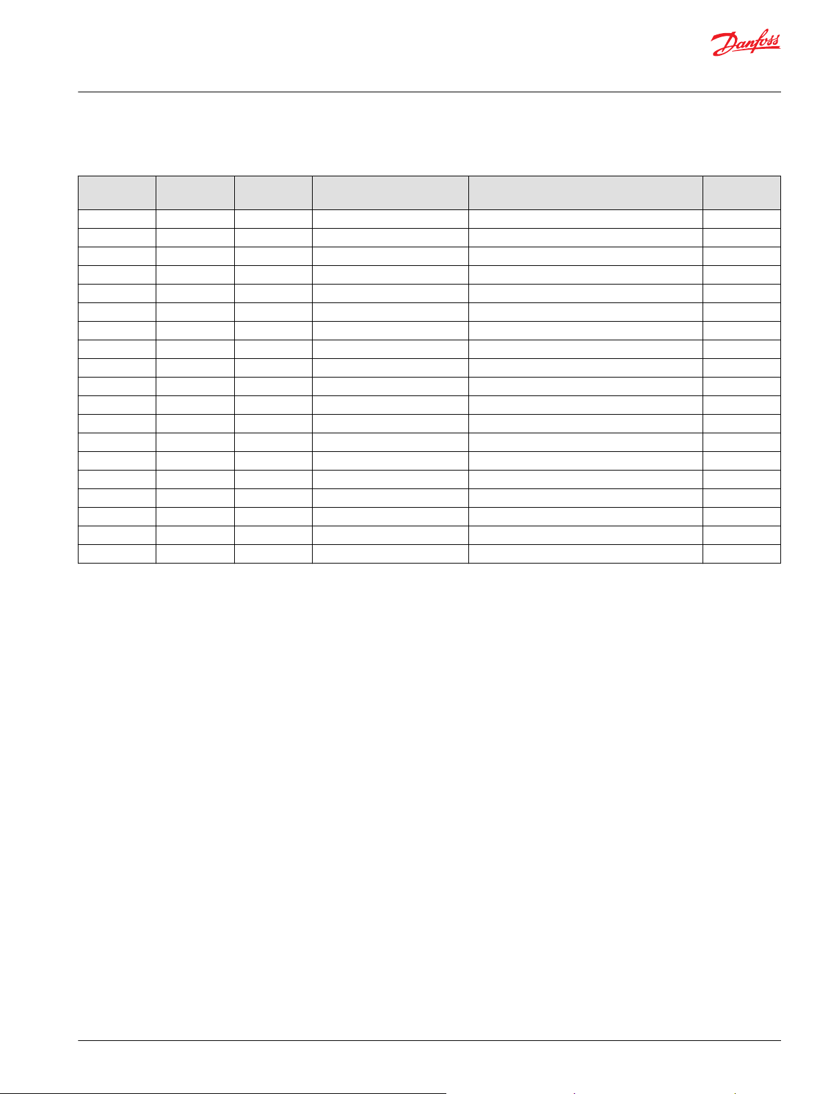
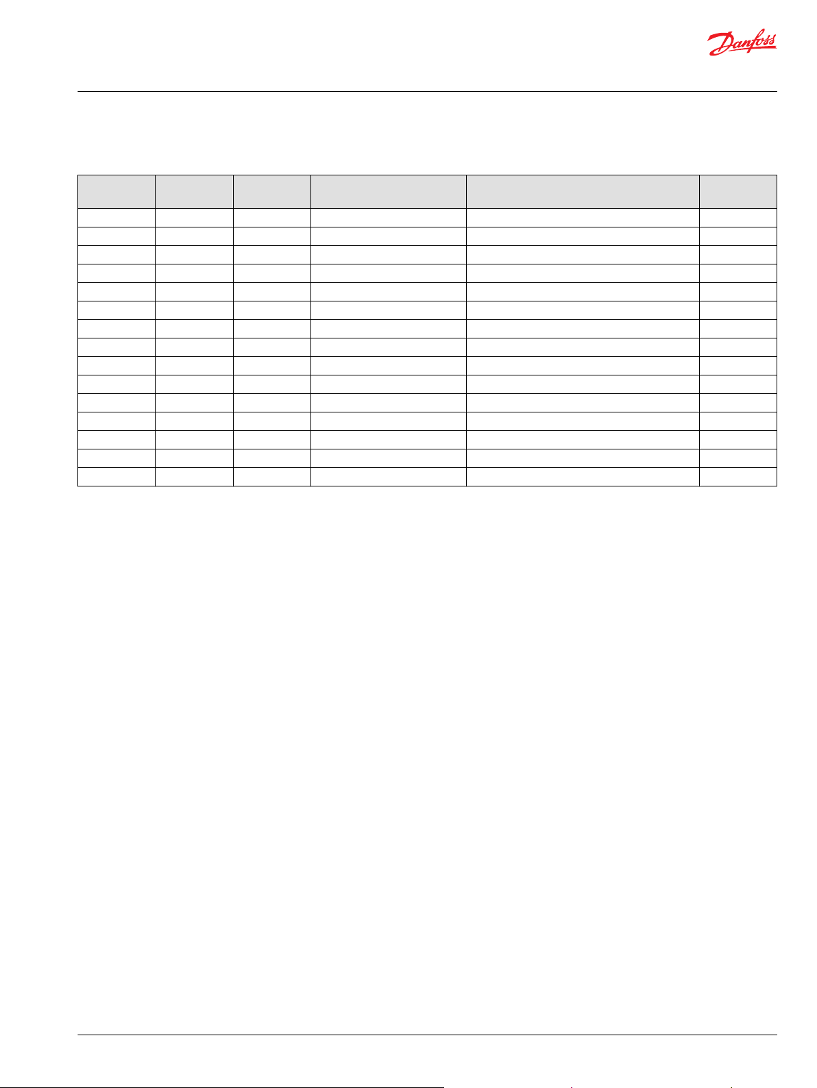
Order code: ENSN
Item Date Begin Date End Part Number Part Name Qty. per
A220 17-37 11156971 Bias piston 1
D103 17-37 11040532 Plug assembly 3
D135 17-37 11040532 Plug assembly 1
D145 17-37 11168710 Control seal 1
D160 17-37 11130807 Dowel pin 2
D175 17-37 527218 Screw 5
D450 17-37 9004104-1160 O-ring 1
D470 17-37 11167267 Screw 1
D480 17-37 612291 Lock nut seal 1
D540 17-37 9004104-0100 O-ring 1
D550 17-37 11130806 Retainer ring 1
D700 17-37 11146859 Proportional solenoid valve assembly, 24v 1
D705 17-37 11155340 Cap 1
D850 17-37 9004104-1160 O-ring 1
D870 17-37 11167267 Screw 1
D880 17-37 612291 Hex nut seal 1
D900 17-37 11139781 Plug assembly 1
QD01 17-37 11212532 SVC control kit 1
QD701 17-37 11189731 Coil assembly 1
Model/Kit
©
Danfoss | December 2021 AX218086484736en-000501 | 9
Page 10
QD01
D175
D103
D896
D135
*D145
D160
D160
*D850
D870
*D880
*D350
D370
*D380
D900
A220
Parts Manual
D1P size 260
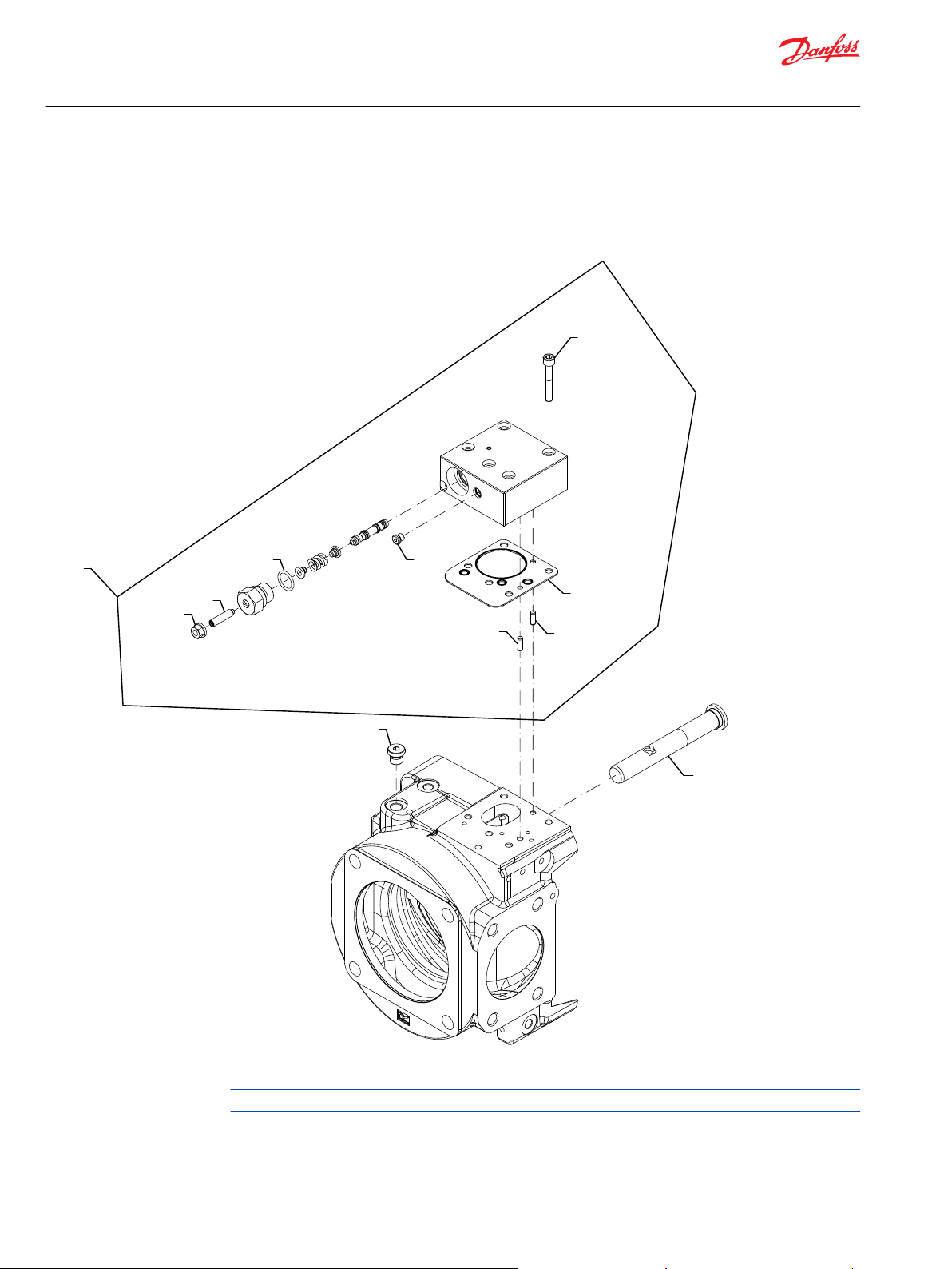
Controls
D1P control NPNR
Parts configuration
* Included in overhaul seal kit Q210
Generic end cap used to show part location only.
10 | © Danfoss | December 2021 AX218086484736en-000501
Page 11
Parts Manual
D1P size 260
Controls
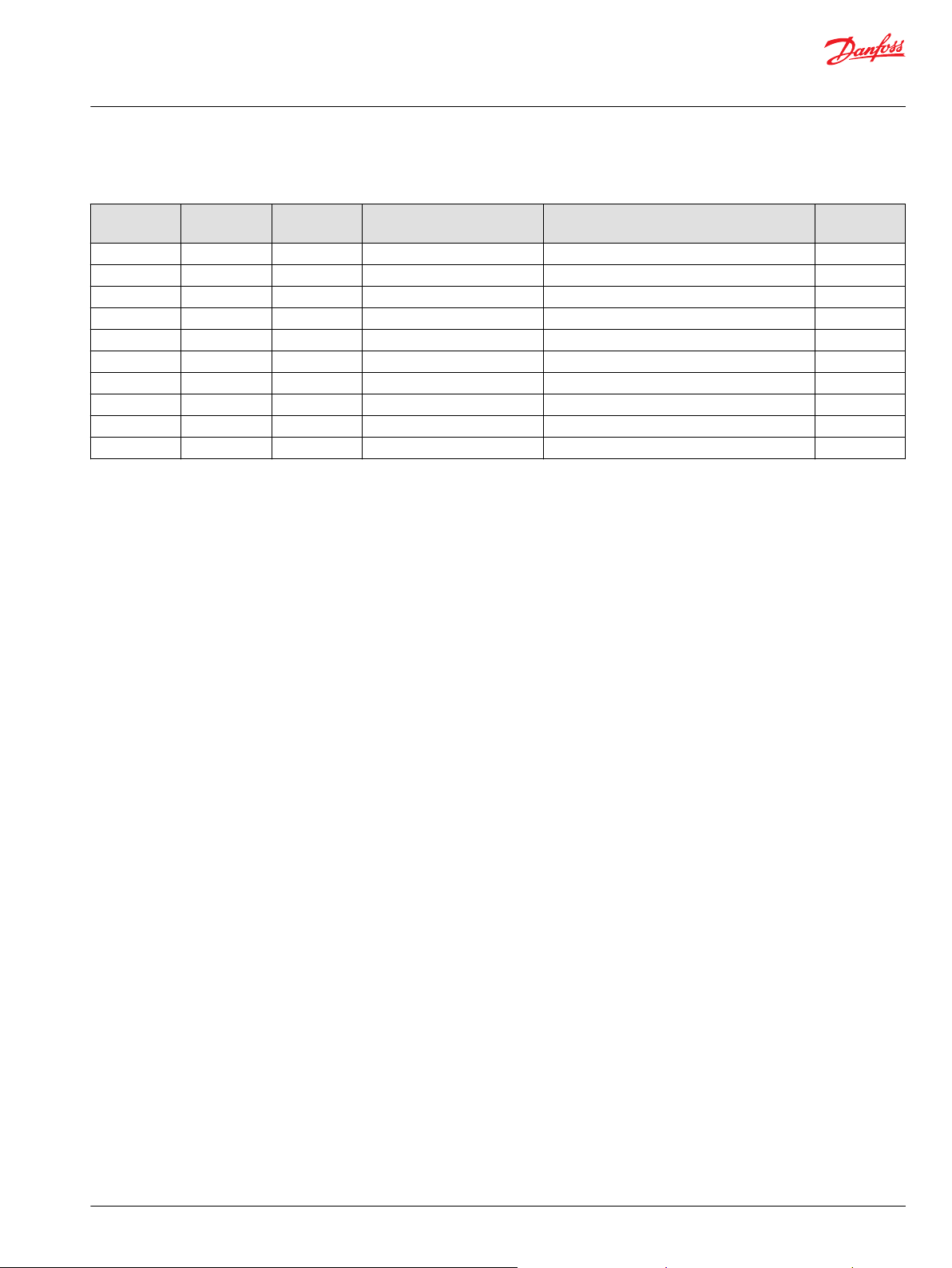
Order code: NPNR
Item Date Begin Date End Part Number Part Name Qty. per
A220 18-32 11187492 Bias piston 1
D103 18-32 11040532 Plug assembly 4
D135 18-32 11040532 Plug assembly 1
D145 18-32 11168710 Control seal 1
D160 18-32 11130807 Dowel pin 2
D175 18-32 527218 Screw 5
D350 18-32 9004104-1160 O-ring 1
D370 18-32 11167267 Screw 1
D380 18-32 612291 (9003508-0008) Lock nut seal 1
D850 18-32 9004104-1160 O-ring 1
D870 18-32 11167267 Screw 1
D880 18-32 612291 (9003508-0008) Lock nut seal 1
D896 18-32 Plug assembly Plug assembly 1
D900 18-32 11139781 Plug assembly 1
QD01 18-32 11221674 Control SVC kit 1
Model/Kit
©
Danfoss | December 2021 AX218086484736en-000501 | 11
Page 12
D175
*D145
D160
D160
D103
*D350
D370
*D380
QD01
D900
A220
Parts Manual
D1P size 260
Controls
D1P control NPNN
Parts configuration
Generic end cap used to show part location only
* Included in overhaul seal kit Q210
12 | © Danfoss | December 2021 AX218086484736en-000501
Page 13
Parts Manual
D1P size 260
Controls
Order code: NPNN
Item Date Begin Date End Part Number Part Name Qty. per
A220 17-10 11187492 Bias piston 1
D103 17-10 11040532 Plug assembly 2
D145 17-10 11168710 Control seal 1
D160 17-10 11130807 Dowel pin 2
D175 17-10 527218 Screw 5
D350 17-10 9004104-1160 O-ring 1
D370 17-10 11167267 Screw 1
D380 17-10 612291 (9003508-0008) Hex nut seal 1
D900 17-10 11139781 Plug assembly 1
QD01 17-10 11196162 SVC control kit 1
Model/Kit
©
Danfoss | December 2021 AX218086484736en-000501 | 13
Page 14
D175
D103
D135
*D145
D160
D160
*D850
D870
*D880
*D380
D370
*D350
QD01
D900
A220
Parts Manual
D1P size 260
Controls
D1P control NPSN
Parts configuration
Generic end cap used to show part location only
* Included in overhaul seal kit Q210
14 | © Danfoss | December 2021 AX218086484736en-000501
Page 15
Parts Manual
D1P size 260
Controls
Order code: NPSN
Item Date Begin Date End Part Number Part Name Qty. per
A220 17-10 11187492 Bias piston 1
D103 17-10 11040532 Plug assembly 1
D135 17-10 11040532 Plug assembly 1
D145 17-10 11168710 Control seal 1
D160 17-10 11130807 Dowel pin 2
D175 17-10 527218 Screw 5
D350 17-10 9004104-1160 O-ring 1
D370 17-10 11171317 Screw 1
D380 17-10 9003509-0008 (612291) Hex nut seal 1
D850 17-10 9004104-1160 O-ring 1
D870 17-10 11171317 Screw 1
D880 17-10 9003509-0008 (612291) Hex nut seal 1
D900 17-10 11139781 Plug assembly 1
QD01 17-10 11196161 SVC control kit 1
Model/Kit
©
Danfoss | December 2021 AX218086484736en-000501 | 15
Page 16
QD01
D175
D550
*D540
D135
D103
3x
D160
D160
*D145
*D850
D870
*D880
*D380
*D350
D370
*D450
D470
*D480
D900
A220
Parts Manual
D1P size 260
Controls
D1P control TPSN
Parts configuration
Generic end cap used to show part location only
* Included in control seal kit QD210
16 | © Danfoss | December 2021 AX218086484736en-000501
Page 17

Parts Manual
D1P size 260
Controls
Order code: TPSN
Item Date Begin Date End Part Number Part Name Qty. per
A220 11169133 Bias piston 1
D103 11040532 Plug assembly 3
D135 11040532 Plug assembly 1
D145 11168710 Control seal 1
D160 11130807 Pin 2
D175 527218 Screw 5
D350 9004104-1160 O-ring 1
D370 11167267 Screw 1
D380 612291 Lock nut seal 1
D450 9004104-1160 O-ring 1
D470 11167267 Screw 1
D480 612291 Lock nut seal 1
D540 9004104-0100 O-ring 1
D550 11130806 Retainer ring 1
D850 9004104-1160 O-ring 1
D870 11167267 Screw 1
D880 612291 Hex nut seal 1
D900 11139781 Plug assembly 1
QD01 11180173 SVC control kit () 1
Model/Kit
©
Danfoss | December 2021 AX218086484736en-000501 | 17
Page 18

D705
D701
D700
D770
*D880
D870
*D850
*D210
*D190
*D120
D110
D175
D103
*D145
D160
D160
A220
QD02
*D902
QD01
Parts Manual
D1P size 260
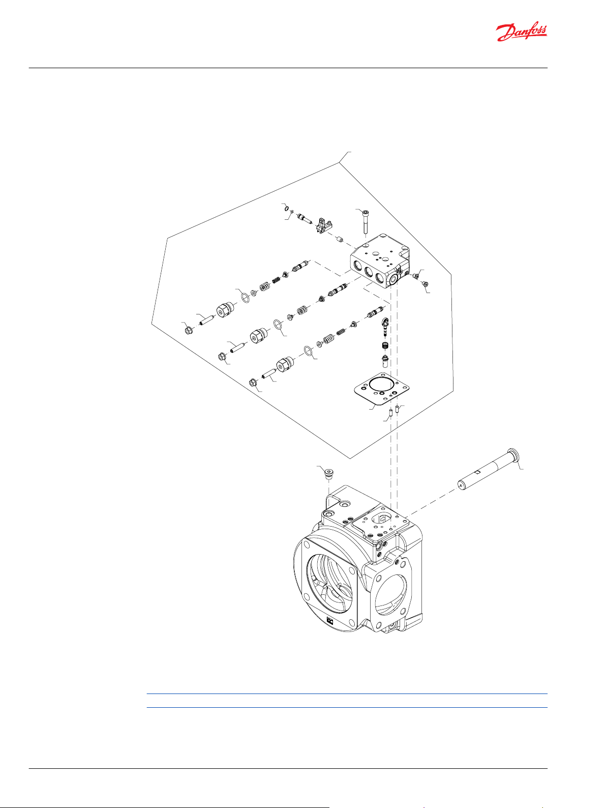
Controls
D1P control NNES
Parts configuration
Generic end cap used to show part location only
18 | © Danfoss | December 2021 AX218086484736en-000501
Page 19

Parts Manual
D1P size 260
Controls
Order code: NNES
Item Date Begin Date End Part Number Part Name Qty. per
A220 17-22 11187492 Bias piston 1
D103 17-22 11040532 Plug assembly 3
D110 17-22 11244238 Screw 1
D120 17-22 9003509-0006 Hex nut seal 1
D145 17-22 11168710 Control seal 1
D160 17-22 11130807 Dowel pin 2
D175 17-22 527218 Screw 5
D190 17-22 9004104-1200 O-ring 1
D210 17-22 11130945 O-ring 1
D700 17-22 11146859 Proportional solenoid valve assembly, 24v 1
D705 17-22 11155340 Cap 1
D770 17-22 11137994 Screw 4
D850 17-22 9004104-1160 O-ring 1
D870 17-22 11167267 Screw 1
D880 17-22 612291 (9003508-0008) Lock nut seal 1
D902 17-22 11135346 Ring seal 1
QD01 17-22 11196157 SVC control kit 1
QD02 17-22 11196160 SVC shuttle valve kit 1
Model/Kit
©
Danfoss | December 2021 AX218086484736en-000501 | 19
Page 20

* D902
* D145
* D380
* D350
* D190
* D120
* D540
D550
D110
D180
D170
D103
11x
* D210
D770
D701
D700
D705
D370
* D480
* D450
D470
QD01
A220
D160
D160
QD02
Parts Manual
D1P size 260
Controls
D1P control TPE2
Parts configuration
Generic end cap used to show part location only
* Included in overhaul seal kit Q210
20 | © Danfoss | December 2021 AX218086484736en-000501
Page 21

Parts Manual
D1P size 260
Controls
Order code: TPE2
Item Date Begin Date End Part Number Part Name Qty. per
A220 16-01 11156971 Bias piston 1
D103 16-01 11040532 Plug assembly 11
D110 16-01 11244238 Screw 1
D120 16-01 9003509-0006 Hex nut seal 1
D145 16-01 11168710 Seal 1
D160 16-01 11130807 Dowel pin 2
D170 16-01 11125762 Screw 3
D180 16-01 11128407 Screw 2
D190 16-01 9004104-1200 O-ring 1
D210 16-01 11130945 O-ring 1
D350 16-01 9004104-1160 O-ring 1
D370 16-01 11167267 Screw 1
D380 16-01 612291 (9003508-0008) Lock nut seal 1
D450 16-01 9004104-1160 O-ring 1
D470 16-01 11167267 Screw 1
D480 16-01 612291 (9003508-0008) Lock nut seal 1
D540 16-01 9004104-0100 O-ring 1
D550 16-01 11130806 Retainer ring 1
D700 16-01 11146859 Solenoid 1
D701 16-01 11189731 Coil assembly 1
D705 16-01 11155340 Solenoid cap 1
D770 16-01 11137994 Screw 4
D902 16-01 11135346 Seal 1
QD01 16-01 11180172 SVC control kit 1
QD02 16-01 11153191 SVC shuttle valve kit 1
Model/Kit
©
Danfoss | December 2021 AX218086484736en-000501 | 21
Page 22

D705
D701
D700
D770
*D210
*D380
D370
*D350
*D190
*D120
D110
D175
*D145
D103
D645
D160
D160
D900
A220
QD01
Parts Manual
D1P size 260
Controls
D1P control NPE0
Parts configuration
* Included in overhaul seal kit Q210
Generic endcap used to show part location only.
22 | © Danfoss | December 2021 AX218086484736en-000501
Page 23

Parts Manual
D1P size 260
Controls
Order code: NPE0
Item Date Begin Date End Part Number Part Name Qty. per
A220 19-24 11187492 Bias piston 1
D103 19-24 11040532 Plug assembly 5
D110 19-24 11126005 Screw 1
D120 19-24 9003509-0006 Hex nut seal 1
D145 19-24 11168710 Control seal 1
D160 19-24 11130807 Dowel pin 2
D175 19-24 527218 Screw 5
D190 19-24 9004104-1200 O-ring 1
D210 19-24 11130945 O-ring 1
D350 19-24 9004104-1160 O-ring 1
D370 19-24 11167267 Screw 1
D380 19-24 612291 Lock nut seal 1
D645 19-24 11187420 Snap ring 1
D700 19-24 11146859 Proportional solenoid 1
D705 19-24 11155340 Solenoid cap, plastic 1
D900 19-24 11139781 Plug assembly 1
QD01 19-24 11282621 SVC control kit 1
Model/Kit
©
Danfoss | December 2021 AX218086484736en-000501 | 23
Page 24

D705
D701
D700
D770
*D210
*D380
D370
*D350
*D190
*D120
D110
D175
D103
D645
*D145
D160
D160
QD01
QD02
*D902
A220
Parts Manual
D1P size 260
Controls
D1P control NPE2
Parts configuration
* Included in overhaul seal kit Q210
Generic endcap used to show part location only.
24 | © Danfoss | December 2021 AX218086484736en-000501
Page 25

Parts Manual
D1P size 260
Controls
Order code: NPE2
Item Date Begin Date End Part Number Part Name Qty. per
A220 19-24 11187492 Bias piston 1
D103 19-24 11040532 Plug assembly 5
D110 19-24 11126005 Screw 1
D120 19-24 9003509-0006 Hex nut seal 1
D145 19-24 11168710 Control seal 1
D160 19-24 11130807 Dowel pin 2
D175 19-24 527218 Screw 5
D190 19-24 9004104-1200 O-ring 1
D210 19-24 11130945 O-ring 1
D350 19-24 9004104-1160 O-ring 1
D370 19-24 11167267 Screw 1
D380 19-24 612291 Lock nut seal 1
D645 19-24 11187420 Snap ring 1
D700 19-24 11146859 Proportional solenoid 1
D705 19-24 11155340 Solenoid cap, plastic 1
D900 19-24 11131608 Plug assembly 1
D902 19-24 11135346 Seal ring 1
QD01 19-24 11282621 SVC control kit 1
QD02 19-24 11153191 SVC shuttle valve kit 1
Model/Kit
©
Danfoss | December 2021 AX218086484736en-000501 | 25
Page 26

E100
E110
E120
QE01
E110
E100
E130
E120
QE01
(A, S, T)
(P)
Parts Manual
D1P size 260
Input shaft
D1P 260 shaft A-T
Parts configuration
Generic end cap used to show part location only
26 | © Danfoss | December 2021 AX218086484736en-000501
Page 27

Parts Manual
D1P size 260
Input shaft
Order code: A
Item Date Begin Date End Part Number Part Name Qty. per
E100 16-42 11173294 Shaft 1
E110 16-42 11156871 Shaft bearing 1
E120 16-42 11156897 Retainer ring 1
QE01 16-42 11189648 SVC shaft kit 1
Order code: S
E100 16-42 11173293 Shaft 1
E110 16-42 11156871 Shaft bearing 1
E120 16-42 11156897 Retainer ring 1
QE01 16-42 11189647 SVC shaft kit 1
Order code: T
E100 16-42 11156870 Shaft 1
E110 16-42 11156871 Shaft bearing 1
E120 16-42 11156897 Retainer ring 1
QE01 16-42 11189650 SVC shaft kit 1
Model/Kit
Order code: P
E100 16-42 11173295 Shaft 1
E110 16-42 11156871 Shaft bearing 1
E120 16-42 11156897 Retainer ring 1
E130 16-42 11173297 Shaft key 1
QE01 16-42 11189649 SVC shaft kit 1
©
Danfoss | December 2021 AX218086484736en-000501 | 27
Page 28

QE01
E120
E110
E100
E130
Parts Manual
D1P size 260
Input shaft
D1P 260 shaft K
Parts configuration
Generic housing used to show part location only.
28 | © Danfoss | December 2021 AX218086484736en-000501
Page 29

Parts Manual
D1P size 260
Input shaft
Order code: K
Item Date Begin Date End Part Number Part Name Qty. per
E100 18-36 11216648 3in straight key shaft 1
E110 18-36 11156871 Shaft bearing 1
E120 18-36 11156897 Retainer ring 1
E130 18-36 11223862 Shaft key 1
QE01 18-36 11223866 SVC shaft kit 1
Model/Kit
©
Danfoss | December 2021 AX218086484736en-000501 | 29
Page 30

* F130
F160
F110
* F120
F100
* F230
* F220
* F210
QF01
* F120
F140
F150
F180
F110
(E4 used prior to 20-45)
F150
F110
*F120
*F130
F110
*F120
F160
F100
*F230
*F220
F210
QF01
(E4 used 20-45 and after)
F140
F180
Parts Manual
D1P size 260
Mounting flange
D1P 260 mounting flange E4
Parts configuration
* Included in overhaul seal kit Q210
30 | © Danfoss | December 2021 AX218086484736en-000501
Page 31

Parts Manual
D1P size 260
Mounting flange
Order code: E4
Item Date Begin Date End Part Number Part Name Qty. per
F100 16-01 11238549 Housing (SB-2020-042 on page 53) 1
F110 16-01 11164808 Set screw 2
F120 16-01 11125710 Hex nut 2
F130 16-01 20-44 11166685 O-ring (SB-2020-042 on page 53) 1
F130 20-45 11197602 Gasket 1
F140 16-01 11167122 Plug assembly 1
F150 16-01 11167122 Plug assembly 1
F160 16-01 11167122 Plug assembly 1
F180 16-01 11166688 Screw 4
F210 16-01 11156878 Retainer ring 1
F220 16-01 11156879 Carrier seal assembly 1
F230 16-01 11166687 O-ring 1
QF01 16-01 11168253 SVC shaft seal kit 1
Model/Kit
©
Danfoss | December 2021 AX218086484736en-000501 | 31
Page 32

QF01
F210
*F220
*F230
F140
F180
F150
*F120
F110
*F130
F110
*F120
F160
*F340
*F318
F315
*F305
F330
QF02
F100
Parts Manual
D1P size 260
Mounting flange
D1P 260 mounting flange EA
Parts configuration
* Included in overhaul seal kit Q210
32 | © Danfoss | December 2021 AX218086484736en-000501
Page 33

Parts Manual
D1P size 260
Mounting flange
Order code: EA
Item Date Begin Date End Part Number Part Name Qty. per
F100 18-49 11201156 Housing, with ANSR 1
F110 18-49 11164808 Set screw 2
F120 18-49 11125710 Hex nut seal 2
F130 18-49 11166685 O-ring 1
F140 18-49 11167122 Plug assembly 1
F150 18-49 11167122 Plug assembly 1
F160 18-49 11167122 Plug assembly 1
F180 18-49 11166688 Screw 4
F210 18-49 11156878 Retainer ring 1
F220 18-49 11156879 Carrier seal assembly 1
F230 18-49 11166687 O-ring 1
F305 18-49 9004104-0350 O-ring 1
F315 18-49 11201149 ANSR spacer 1
F318 18-49 9004104-0350 O-ring 1
F340 18-49 11201145 Screw 4
QF01 18-49 11168253 SVC shaft seal kit 1
QF02 18-49 11233558 SVC angle sensor kit 1
Model/Kit
©
Danfoss | December 2021 AX218086484736en-000501 | 33
Page 34

QG01
G610
G600
G620
G235
G250
G253
G255
G200
G210
G260
G300
G125
G225
G100
9x
Parts Manual
D1P size 260
Endcap
D1P 260 endcap Y3
Parts configuration
Generic orifice (G130 and G140) used to show part location only.
34 | © Danfoss | December 2021 AX218086484736en-000501
Page 35

Parts Manual
D1P size 260
Endcap
Order code: Y3 (clockwise configuration)
Item Date Begin Date End Part Number Part Name Qty. per
G100 15-35 11156886 Endcap assembly 1
G125 15-35 11040532 Plug assembly 9
G200 15-35 11156890 Shaft bearing 1
G210 15-35 11125269 Dowel pin 2
G225 15-35 11135349 Plug assembly 1
G235 15-35 11135349 Plug assembly 1
G250 15-35 11135349 Plug assembly 1
G253 15-35 11040532 Plug assembly 1
G255 15-35 11139781 Plug assembly 1
G260 15-35 11156891 Bushing 1
G300 15-35 11166689 Dowel pin 1
G600 15-35 11126107 Impeller 1
G610 15-35 11127784 Retainer ring 1
G620 15-35 11127784 Retainer ring 1
QG01 15-35 11153195 SVC impeller kit, CW 1
Model/Kit
Order code: Y3 (counterclockwise configuration)
Item Date Begin Date End Part Number Part Name Qty. per
G100 15-35 11190513 Endcap assembly 1
G125 15-35 11040532 Plug assembly 9
G200 15-35 11156890 Shaft bearing 1
G210 15-35 11125269 Dowel pin 2
G225 15-35 11135349 Plug assembly 1
G235 15-35 11135349 Plug assembly 1
G250 15-35 11135349 Plug assembly 1
G253 15-35 11040532 Plug assembly 1
G255 15-35 11139781 Plug assembly 1
G260 15-35 11156891 Bushing 1
G300 15-35 11166689 Dowel pin 1
G600 15-35 11180818 Impeller 1
G610 15-35 11127784 Retainer ring 1
G620 15-35 11127784 Retainer ring 1
QG01 15-35 11196163 SVC impeller kit, CCW 1
Model/Kit
©
Danfoss | December 2021 AX218086484736en-000501 | 35
Page 36

QH01
H200
*H110
H100
H130
H140
H120
H150
Parts Manual
D1P size 260
Auxiliary mounting flange
D1P aux mounting A1, A3
Parts configuration
Generic endcap used to show part location only
* Included in overhaul seal kit Q210
36 | © Danfoss | December 2021 AX218086484736en-000501
Page 37

Parts Manual
D1P size 260
Auxiliary mounting flange
Order code: A1
Item Date Begin Date End Part Number Part Name Qty. per
H100 16-01 11137727 Adapter 1
H110 16-01 11130792 O-ring 1
H120 16-01 11130802 Screw 4
H130 16-01 4800482 Seal 1
H140 16-01 11139662 Hex screw 2
H150 16-01 4460586 Cover 1
H200 16-01 11138417 Coupling 1
QH01 16-01 11160946 SVC aux pad kit 1
Order code: A3
H100 16-01 11137727 Adapter 1
H110 16-01 11130792 O-ring 1
H120 16-01 11130802 Screw 4
H130 16-01 4800482 Seal 1
H140 16-01 11139662 Hex screw 2
H150 16-01 4460586 Cover 1
H200 16-01 11190214 Coupling 1
QH01 16-01 11196164 SVC aux pad kit 1
Model/Kit
©
Danfoss | December 2021 AX218086484736en-000501 | 37
Page 38

QH01
H200
*H110
H100
H130
H140
H120
H150
(B1, B2)
QH01
H200
*H110
H100
H120
H130
H150
H140
(BA)
Parts Manual
D1P size 260
Auxiliary mounting flange
D1P aux mounting B1, B2, BA, BB
Parts configuration
* Included in overhaul seal kit Q210
Generic endcap used to show part location only.
38 | © Danfoss | December 2021 AX218086484736en-000501
Page 39

Parts Manual
D1P size 260
Auxiliary mounting flange
Common parts
Item Date Begin Date End Part Number Part Name Qty. per
H100 16-01 11129048 Adapter 1
H110 16-01 11130792 O-ring 1
H120 16-01 11130802 Screw 4
H130 16-01 9004104-1540 O-ring 1
H140 16-01 509528 Hex screw 2
H150 16-01 4460370 Cover, SAE B flange 1
Order code: B1
H200 16-01 11138204 Coupling 1
QH01 16-01 11160947 SVC aux pad kit 1
Order code: B2
H200 19-20 11229286 Coupling 1
QH01 19-20 11229287 SVC aux pad kit 1
Model/Kit
Order code: BA (90° orientation)
H200 17-48 11138204 Coupling 1
QH01 17-48 11160947 SVC aux pad kit 1
Order code: BB (45° orientation)
H200 18-51 11138204 Coupling 1
QH01 18-51 11160947 SVC aux pad kit 1
©
Danfoss | December 2021 AX218086484736en-000501 | 39
Page 40

QH01
H200
*H110
H100
H130
H120
H150
H140
Parts Manual
D1P size 260
Auxiliary mounting flange
D1P aux mounting C5, C9
Parts configuration
Generic endcap used to show part location only
* Included in overhaul seal kit Q210
40 | © Danfoss | December 2021 AX218086484736en-000501
Page 41

Parts Manual
D1P size 260
Auxiliary mounting flange
Order code: C5
Item Date Begin Date End Part Number Part Name Qty. per
H100 14-38 11156542 Adapter 1
H110 14-38 11130792 O-ring 1
H120 14-38 11165544 Screw 4
H130 14-38 11081805 C-pad seal 1
H140 14-38 509528 Hex screw 4
H150 14-38 8801060 Cover 1
H200 14-38 11153130 Coupling 1
QH01 14-38 11160948 SVC aux pad kit 1
Order code: C9
H100 17-16 11189976 Adapter 1
H110 17-16 11130792 O-ring 1
H120 17-16 11130802 Screw 4
H130 17-16 11081805 C-pad seal 1
H140 17-16 509528 Hex screw 4
H150 17-16 8801060 Cover 1
H200 17-16 11189848 Coupling 1
QH01 17-16 11196165 SVC aux pad kit 1
Model/Kit
©
Danfoss | December 2021 AX218086484736en-000501 | 41
Page 42

* H110
H200
H140
H150
H130
H120
H100
QH01
QH01
H200
*H110
*H108
H105
H120
H100
H107
H130
H140
(D2, D5)
(E2)
Parts Manual
D1P size 260
Auxiliary mounting flange
D1P aux mounting D2, D5, E2
Parts configuration
Generic endcap used to show part location only
* Included in overhaul seal kit Q210
42 | © Danfoss | December 2021 AX218086484736en-000501
Page 43

Parts Manual
D1P size 260
Auxiliary mounting flange
Order code: D2
Item Date Begin Date End Part Number Part Name Qty. per
H100 17-14 11165411 Rear adapter 1
H105 17-14 11165410 Front adapter 1
H107 17-14 11158926 Screw 8
H108 17-14 9004104-1580 O-ring 1
H110 17-14 11130792 O-ring 1
H120 17-14 11165544 Screw 4
H130 17-14 9004104-1620 O-ring 1
H140 17-14 11024165 Hex screw 4
H150 17-14 338400 Cover 1
H200 17-14 11189848 Coupling 1
QH01 17-14 11196166 SVC aux pad kit 1
Order code: D5
H100 17-14 11165411 Rear adapter 1
H105 17-14 11165410 Front adapter 1
H107 17-14 11158926 Screw 8
H108 17-14 9004104-1580 O-ring 1
H110 17-14 11130792 O-ring 1
H120 17-14 11165544 Screw 4
H130 17-14 9004104-1620 O-ring 1
H140 17-14 11024165 Hex screw 4
H150 17-14 338400 Cover 1
H200 17-14 11180061 Coupling 1
QH01 17-14 11170706 SVC aux pad kit 1
Model/Kit
Order code: E2
H100 16-01 11136088 Adapter 1
H110 16-01 11130792 O-ring 1
H120 16-01 11130802 Screw 4
H130 16-01 505068 O-ring 1
H140 16-01 11024165 Hex screw 4
H150 16-01 750422 Cover 1
H200 16-01 11138418 Coupling 1
QH01 16-01 11160950 SVC aux pad kit 1
©
Danfoss | December 2021 AX218086484736en-000501 | 43
Page 44

QH01
H200
*H110
H100
H130
H150
H140
H120
Parts Manual
D1P size 260
Auxiliary mounting flange
D1P aux mounting E3
Parts configuration
Generic endcap used to show part location only.
* Included in overhaul seal kit Q210
44 | © Danfoss | December 2021 AX218086484736en-000501
Page 45

Parts Manual
D1P size 260
Auxiliary mounting flange
Order code: E3
Item Date Begin Date End Part Number Part Name Qty. per
H100 16-21 11136088 Adapter 1
H110 16-21 11130792 O-ring 1
H120 16-21 11130802 Screw 4
H130 16-21 505068 O-ring 1
H140 16-21 11024165 Hex screw 4
H150 16-21 750422 SAE-E flange cover 1
H200 16-21 11178715 Coupling 1
QH01 16-21 11179969 SVC aux pad kit 1
Model/Kit
©
Danfoss | December 2021 AX218086484736en-000501 | 45
Page 46

* H110
QH01
H100
H120
Parts Manual
D1P size 260
Auxiliary mounting flange
D1P aux mounting NN
Parts configuration
Generic endcap used to show part location only
* Included in overhaul seal kit Q210
46 | © Danfoss | December 2021 AX218086484736en-000501
Page 47

Parts Manual
D1P size 260
Auxiliary mounting flange
Order code: NN
Item Date Begin Date End Part Number Part Name Qty. per
H100 15-16 11159172 Cover (without aux) 1
H110 15-16 505068 O-ring 1
H120 15-16 11130802 Screw 4
QH01 15-16 11160951 SVC aux pad kit 1
Model/Kit
©
Danfoss | December 2021 AX218086484736en-000501 | 47
Page 48

QR01
R100
A210
QR02
R130
R130
A000
QA01
A110
QA02
A140
A100
QA03
A310
A320
A330
A230
Washer number and thickness may differ
depending on kit group height
Parts Manual
D1P size 260
Special hardware
D1P 260 special hardware NNN
Parts configuration
Generic housing and bias piston used to show part location only. This option is available in clockwise and
counterclockwise rotation. Please order accordingly.
48 | © Danfoss | December 2021 AX218086484736en-000501
Page 49

Parts Manual
D1P size 260
Special hardware
Common parts
Item Date Begin Date End Part Number Part Name Qty. per
A110 16-01 11156953 Slipper retainer 1
A140 16-01 11156959 Slipper guide retainer 1
A210 16-01 11162217 Bias rod, long 1
A230 16-01 11156972 Spring 1
A310 16-01 11156973 Servo rod 1
A320 16-01 11156974 Servo piston 1
A330 16-01 11156975 Spring 1
R100 16-01 11156976 Swashplate 1
R130 16-01 11142920 Screw 4
QA01 16-01 11168257 SVC piston kit 1
QA02 16-01 11187628 SVC spring kit 1
QA03 16-01 11201163 SVC washer kit 1
QR01 16-01 11187631 SVC bearing kit 1
QR02 16-01 11189655 SVC holder kit 1
Model/Kit
Order code: NNN (clockwise)
A000 16-01 11156945 Kit assembly 1
A100 16-01 11247345 Cylinder block kit 1
A120 16-01 11156957 Washer 1
Order code: NNN (counterclockwise)
A000 16-01 11190501 Kit assembly 1
A100 16-01 11190500 Cylinder block kit 1
A120 16-01 11156590 Washer 1
©
Danfoss | December 2021 AX218086484736en-000501 | 49
Page 50

G130
G140
G254
G130
G140
(NNN)
(NNF)
Parts Manual
D1P size 260
Special hardware
D1P 260 orifice NNN, NNF
Parts configuration
50 | © Danfoss | December 2021 AX218086484736en-000501
Page 51

Parts Manual
D1P size 260
Special hardware
Order code: NNN
Item Date Begin Date End Part Number Part Name Qty. per
G130 16-01 516598 Orifice 1
G140 16-01 11131955 Orifice 1
Order code: NNF
G130 16-01 516598 Orifice 1
G140 16-01 11131955 Orifice 1
G254 16-01 11124768 Edge filter 1
Model/Kit
©
Danfoss | December 2021 AX218086484736en-000501 | 51
Page 52

Parts Manual
D1P size 260
Overhaul seal kit
D1P 260 seal kit
Item Date Begin Date End Part Number Part Name Qty. per
Q210 16-01 11261852 SVC overhaul seal kit
D120 16-01 9003509-0006 Hex nut seal 1
D145 16-01 11168710 Seal 1
D190 16-01 9004104-1200 O-ring 1
D210 16-01 11130945 O-ring 1
D350 16-01 9004104-1160 O-ring 1
D380 16-01 612291 Hex nut seal 1
D450 16-01 9004104-1160 O-ring 1
D480 16-01 612291 Lock nut seal 1
D540 16-01 9004104-0100 O-ring 1
D850 16-01 9004104-1160 O-ring 1
D880 16-01 612291 Lock nut seal 1
D902 16-01 11135346 Seal 1
F120 16-01 11125710 Hex nut 2
F130 16-01 11197602 Gasket 1
F220 16-01 11156879 Carrier seal assembly 1
F230 16-01 11166687 O-ring 1
F305 16-01 9004104-0350 O-ring 1
F318 16-01 9004104-0350 O-ring 1
F340 16-01 11201145 Screw 1
H108 16-01 9004104-1580 O-ring 1
H110 16-01 11130792 O-ring 1
H110 16-01 505068 O-ring 1
Model/Kit
52 | © Danfoss | December 2021 AX218086484736en-000501
Page 53

Parts Manual
D1P size 260
Service bulletins
SB-2020-042
Products affected
D1 pumps
Subject
Housing and end cap seal design change
Description
Danfoss Power Solutions has made a product improvement to the D1P 260cc open circuit pump housing
and end cap seal. The O-ring groove in the housing has been removed and the O-ring has been replaced
with a metal gasket.
The new gasket and housing can be directly substituted for the O-ring seal and the old housing. The Oring seal will remain as a service part. The old housing will become obsolete.
The overhaul seal kit part number changes.
Models affects
D1P 260cc open circuit pumps
Serial numbers affected
This change became effective at: H-XX-XX-XXXXX (30 October 2020)
Part numbers affected
Description Old part number New part number
End cap O-ring 11166685 N/A
Housing 11156875 11238549
Endcap gasket N/A 11197602
Overhaul seal kit 11187634 11261852
©
Danfoss | December 2021 AX218086484736en-000501 | 53
Page 54

Parts Manual
D1P size 260
Service bulletins
Parts disposition
Interchangeable – When using both the new gasket seal and new housing
54 | © Danfoss | December 2021 AX218086484736en-000501
Page 55

Danfoss
Power Solutions GmbH & Co. OHG
Krokamp 35
D-24539 Neumünster, Germany
Phone: +49 4321 871 0
Danfoss
Power Solutions ApS
Nordborgvej 81
DK-6430 Nordborg, Denmark
Phone: +45 7488 2222
Danfoss
Power Solutions (US) Company
2800 East 13th Street
Ames, IA 50010, USA
Phone: +1 515 239 6000
Danfoss
Power Solutions Trading
(Shanghai) Co., Ltd.
Building #22, No. 1000 Jin Hai Rd
Jin Qiao, Pudong New District
Shanghai, China 201206
Phone: +86 21 2080 6201
Products we offer:
Hydro-Gear
www.hydro-gear.com
Daikin-Sauer-Danfoss
www.daikin-sauer-danfoss.com
Cartridge valves
•
DCV directional control
•
valves
Electric converters
•
Electric machines
•
Electric motors
•
Gear motors
•
Gear pumps
•
Hydraulic integrated
•
circuits (HICs)
Hydrostatic motors
•
Hydrostatic pumps
•
Orbital motors
•
PLUS+1® controllers
•
PLUS+1® displays
•
PLUS+1® joysticks and
•
pedals
PLUS+1® operator
•
interfaces
PLUS+1® sensors
•
PLUS+1® software
•
PLUS+1® software services,
•
support and training
Position controls and
•
sensors
PVG proportional valves
•
Steering components and
•
systems
Telematics
•
Danfoss Power Solutions is a global manufacturer and supplier of high-quality hydraulic and
electric components. We specialize in providing state-of-the-art technology and solutions
that excel in the harsh operating conditions of the mobile off-highway market as well as the
marine sector. Building on our extensive applications expertise, we work closely with you to
ensure exceptional performance for a broad range of applications. We help you and other
customers around the world speed up system development, reduce costs and bring vehicles
and vessels to market faster.
Danfoss Power Solutions – your strongest partner in mobile hydraulics and mobile
electrification.
Go to www.danfoss.com for further product information.
We offer you expert worldwide support for ensuring the best possible solutions for
outstanding performance. And with an extensive network of Global Service Partners, we also
provide you with comprehensive global service for all of our components.
Local address:
Danfoss can accept no responsibility for possible errors in catalogues, brochures and other printed material. Danfoss reserves the right to alter its products without notice. This also applies to products
already on order provided that such alterations can be made without subsequent changes being necessary in specifications already agreed.
All trademarks in this material are property of the respective companies. Danfoss and the Danfoss logotype are trademarks of Danfoss A/S. All rights reserved.
©
Danfoss | December 2021 AX218086484736en-000501
 Loading...