

Page 1
MAKING MODERN LIVING POSSIBLE
User Manual
PLUS+1 Compliant
CYPR1
www.powersolutions.danfoss.com
Function Block
Page 2

User Manual
PLUS+1 Compliant CYPR1 Function Block
2
AQ00000201 · 00-00 · July 2015
©
All trademarks in t
PLUS+1, GUIDE, and Sauer
PLUS+1 GUIDE, PLUS+1 Compliant, and Sauer
Company
Revision History
Revision Date Comment
Rev 00-00 July 2015
2015 Danfoss Power Solutions (US) Company. All rights reserved.
his material are properties of their respective owners.
-Danfoss are trademarks of Danfoss Power Solutions (US) Company. The Danfoss,
-Danfoss logotypes are trademarks of Danfoss Power Solutions (US)
.
Page 3

User Manual
PLUS+1 Compliant
AQ00000201 · Rev 00-00 · July 2015
3
CYPR1 Function Block
Contents
CYPR1 Function Block ........................................................................................................................................ 4
Overview ......................................................................................................................................................... 4
Inputs ............................................................................................................................................................... 4
Outputs ............................................................................................................................................................ 5
About Function Block Connections...................................................................................................... 7
Fault and Status Logic ............................................................................................................................... 8
Function Block Parameter Values........................................................................................................ 10
Page 4
User Manual
PLUS+1 Compliant
AQ00000201 · Rev 00-00 · July 2015
4
Overview
CYPR1 Function Block
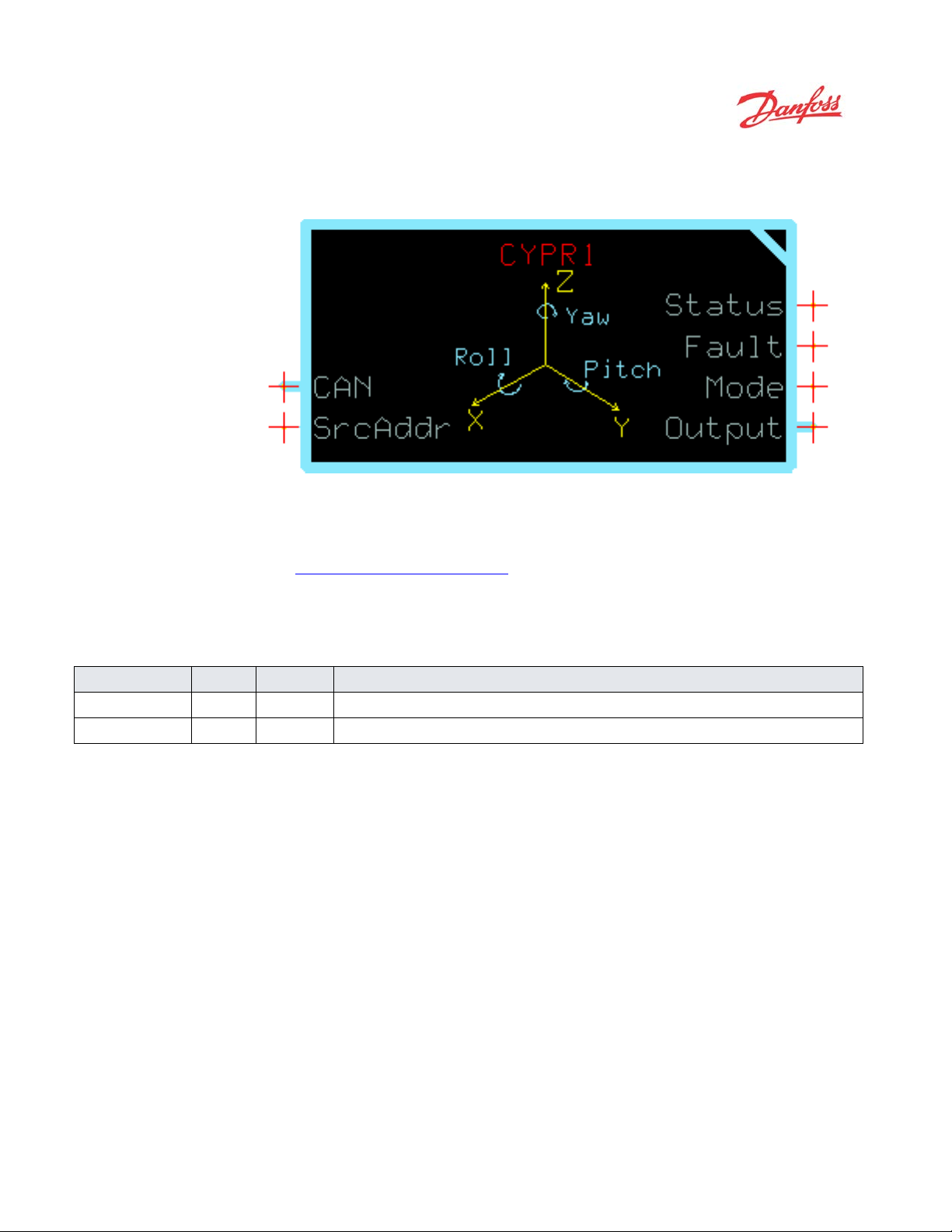
CYPR1 Function Block
This function block outputs X, Y, and Z position data based on measurements from the
CYPR1 Sensor. All signals are received via the CAN communication bus.
See About Function Block Connections on page 7 for an overview of this function block’s
connections and signals.
Inputs
CYPR1 Function Block Inputs
Input Type Range Description
CAN Bus ——
SrcAddr U8 0 to 253
CAN port that receives messages from the CYPR1 sensor.
Source address of the CYPR1 sensor.
Page 5

User Manual
PLUS+1 Compliant
CYPR1Function Block
AQ00000201 · Rev 00-00 · July 2015
5
Outputs
CYPR1Function Block Outputs
Output Type Range Description
Status U16 ——
Reports the function block’s status.
• 0x0000 = Block is OK.
• 0x8008 = SrcAddr or Timeout value is out of range.
CYPR1 Function Block
Fault U16 ——
Mode U8 ——
Output Bus ——
X_Axis S32 Mode 0: 0 to 35999
Mode 1: -17999 to
18000
Mode 2: -9000 to
9000
Mode 3:-10000 to
10000
Y_Axis S32 Mode 0: 0 to 35999
Mode 1: -17999 to
18000
Mode 2: -9000 to
9000
Mode 3:-10000 to
10000
Reports the function block’s faults.
This function block uses a non-standard bitwise scheme to report its status and faults.
• 0x0000 = Block is OK.
• 0x0001 = CAN message not received since startup.
• 0x0002 = CAN message was received, but now has timed out.
• 0x0004 = Received data is reported using an unsupported mode.
• 0x0008 = Received data mode does not match XID.
• 0x0010 = Received axis data is out of range.
• 0x0020 = Sensor reporting that data is degraded.
Indicates the X, Y, and Z data range, units, and sensing mode.
• 0 = Angle Sensing Mode 1, range reported 0 to 359.99 degrees
• 1 = Angle Sensing Mode 1, range reported -179.99 to 180.00 degrees
• 2 = Angle Sensing Mode 2, -90.00 to 90.00 degrees
• 3 = Orientation Mode, -1.0000 to 1.0000 vector
• 255 =Device is in an invalid or unsupported mode.
Bus containing output signals.
X Axis orientation according to reported mode.
1 = 0.01 Degrees for modes 0, 1, 2
1 = 0.0001 Unit Vector for mode 3
Y Axis orientation according to reported mode.
1 = 0.01 Degrees for modes 0, 1, 2
1 = 0.0001 Unit Vector for mode 3
Page 6

User Manual
PLUS+1 Compliant
CYPR1Function Block
6
AQ00000201 · Rev 00-00 · July 2015
CYPR1Function Block Outputs
Output Type Range Description
Z_Axis S32 Mode 0: 0 to 35999
Mode 1: -17999 to
18000
Mode 2: -9000 to
9000
Mode 3:-10000 to
10000
Z Axis orientation according to reported mode.
1 = 0.01 Degrees for modes 0, 1, 2
1 = 0.0001 Unit Vector for mode 3
CYPR1Function Block
Page 7

User Manual
PLUS+1 Compliant
CYPR1Function Block
AQ00000201 · Rev 00-00 · July 2015
7
About Function Block Connections
1
2
unction Block Connections
F
Item Description
1.
2.
3.
4.
5.
6.
CYPR1 Function Block
3
4
5
6
Determines the CAN port connected to the sensor.
Configures the function block to listen for CAN data from the sensor’s network address.
Reports the status of the function block.
Reports the fault of the function block.
Reports the active mode of the CYPR1 sensor and indicates how the position data is formatted.
Output bus containing the X, Y, and Z axis position information.
Page 8

User Manual
PLUS+1 Compliant
CYPR1Function Block
8
AQ00000201 · Rev 00-00 · July 2015
Fault Logic
CYPR1Function Block
Fault and Status Logic
Unlike most other PLUS+1 compliant function blocks, this function block uses non-standard fault
codes.
Fault Hex Binary Cause Response Delay† Latch‡ Correction
No message
received
Timeout 0x0002 00000010 Valid message not
Unsupported
Mode
Mode does
not match
XID
Invalid CAN
Data
Data
Degraded
†
A delayed fault is reported if the detected fault condition persists for a specified delay time. A delayed fault cannot be cleared until the fault
condition remains undetected for the delay time.
‡
The function block maintains a latched fault report until the latch releases.
0x0001 00000001 No valid CAN
message from
specified source
address has been
received since
startup.
received within
expected time
window.
0x0004 00000100 Received message
indicates data
reported using an
unsupported mode.
0x0008 00001000 Received message
indicates data
reported using an
unsupported mode
and XID
combination.
0x0010 00010000 Received data is
outside expected
ranges.
0x0020 00100000 Sensor elements are
unable to report
with optimal
accuracy.
Outputs remain at
zero.
Previous outputs are
reported.
Outputs set to zero. N N Use fault signal to trigger
Outputs set to zero. N
Outputs set to zero. N N Use fault signal to trigger
Outputs reported,
but data is less
accurate.
N
N Use fault signal to trigger
application response. Check that
sensor is properly connected to
CAN bus and correct value for
SrcAddr has been set. Check bus
for physical failure or overload.
Y N Use fault signal to trigger
application response. Check bus
for physical failure or overload.
application response. Verify
attached sensor is set to a
compatible mode. Check bus for
conflicting data from other
sources.
N Use fault signal to trigger
application response. Verify
attached sensor is set to a
compatible mode. Check bus for
conflicting data from other
sources.
application response. Verify
attached sensor is set to a
compatible mode. Check bus for
conflicting data from other
sources.
N
N Check CYPR1 technical
documentation for application
limits and further details on
operation.
Page 9

User Manual
PLUS+1 Compliant
CYPR1Function Block
AQ00000201 · Rev 00-00 · July 2015
9
CYPR1 Function Block
Status Logic
Status Hex Binary Cause Response Delay† Latch‡ Correction
Parameter
out of range
†
A delayed fault is reported if the detected fault condition persists for a specified delay time. A delayed fault cannot be cleared until the fault
condition remains undetected for the delay time.
‡
The function block maintains a latched fault report until the latch releases.
0x8008 10001000 SrcAddr or
Timeout value is
outside the allowed
range.
Function Block
operates using the
closest valid value.
Data may not be
properly received.
N N Use fault signal to trigger
application response. Adjust the
values to be within their allowed
range, make sure the proper
SrcAddr is set.
Page 10

User Manual
PLUS+1 Compliant
CYPR1Function Block
10
AQ00000201 · Rev 00-00 · July 2015
Function Block Parameter Values
Enter the top-level page of the CYPR1 function block to view and change this function
block's parameters.
CYPR1Function Block
Function Block Parameters
Input Type Range Description
Timeout U16 10 to 10000
The Timeout signal specifies the maximum acceptable period between receiving two consecutive
messages from the CYPR1 sensor. It is recommended to set this value at least 1.5 times the sensor’s
specified transmission period.
10 = 10 ms.
Page 11

User Manual
PLUS+1 Compliant CYPR1 Function Block
(This page is intentionally blank.)
Page 12

AQ00000201 · 00-00 · July 2015
www.danfoss.com
©2015 Danfoss Power Solutions (US) Company
Products we offer:
•
•
•
•
•
•
•
•
•
•
•
•
•
• Sensors
Danfoss
Power Solutions
2800 East 13th Street
Ames, IA 50010, USA
Phone: +1 515 239
Danfoss
Power Solutions
Krokamp 35
D
Phone: +49 4321 871
Danfoss
Power Solutions
Nordborgvej 81
DK
Phone: +45 7488 4444
Danfoss
Power Solutions Trading
(Shanghai) Co., Ltd
Building #22, N
Hai Rd
Jin Qiao, Pudong New
District
Shanghai, China 201206
Phone: +86 21 3418 5200
Comatrol
www.comatrol.com
Schwarzmüller
www.schwarzmueller
Turolla
www.turollaocg.com
Hydro
www.hydro
Daikin
www.
Danfo
electronic components. We specialize in providing
excel in the harsh operating conditions of the mobile off
applications expertise, we work closely with our customers to ensure exceptional performance for a
broad ran
We help OEMs around the world speed up system development, reduce costs and bring vehicles to
market faster.
Danfoss
Go to www.
Wherever off
customers, ensuring the best possible solutions for outstanding performance. And with an extensive
network of Global Service Partners, we also provide c
components.
Please contact the
Danfoss can accept no responsibility for possibl e errors in cata logues, brochures and other printed material. Danfoss reserves the right to alter its products without notice. This also applies to products
All trademarks i n this material are property of the res pective companies. Danfoss an d the Danfoss logotype are trademarks of Danfoss Power Solutions (US) Company. All rights reserved.
Bent Axis Motors
Closed Circuit Axial Piston
Pumps and Motors
Displays
Electrohydraulic Power
Steering
Electrohydraulics
Hydraulic Power Steering
Integrated Systems
Joysticks and Control
Handles
Microcontrollers and
Software
Open Circuit Axial Piston
Pumps
Orbital Motors
PLUS+1™ GUIDE
ss Power Solutions is a global manufacturer and supplier of high-quality hydraulic and
state-of-the-art technology and solutions that
-highway market. Building on our extensive
ge of off-highway vehicles.
—Your Strongest Partner in Mobile Hydraulics.
powersolutions.danfoss.com for further product information.
-highway vehicles are at work, so is Danfoss. We offer expert worldwide support for our
omprehensive global service for all of our
Danfoss Power Solution representative nearest you.
Proportional Valves
-Gear
- Sauer-Danfoss
daikin-sauer-danfoss.com
already on order provided that such alterations can be made without subsequential changes being necessary in specifcations already agreed.
-Inverter
-gear.com
US Company
-6000
-inverter.com
Local address:
GmbH & Co. OHG
-24539 Neumünster, Germany
0
ApS
-6430 Nordborg, Denmark
.
o. 1000 Jin
 Loading...