

Page 1
Installation guide
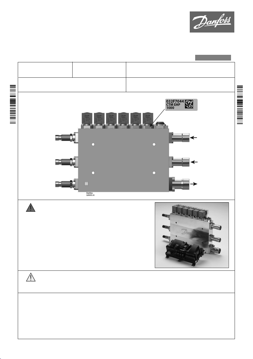
Multi Ejector
type CTM 6
Refrigerant:
R744 with oil
032R9797
Ambient temp. range:
-10 °C – +50 °C / 14 °F – 122 °F
Connector positions
CTM 6
Pressure
transmitter
B
(Pgc)
Pressure
transmitter
)
(P
D
0
Pressure
transmitter
)
(P
rec
Max. Working Pressure:
140 bar / 2031 psi
Ejector Ejector Ejector Ejector Ejector Ejector
1 2 3 4 5 6
Media temp. range:
-10 °C – +50 °C / 14 °F – 122 °F
Max. OPD: 90 bar / 1305 psi
Min. OPD: 0.1 bar / 1.45 psi
ENGINEERING
TOMORROW
Label
Strainer
English
High pressure inlet
A
Suction inlet
C
Receiver
EF
032R9797
The CTM Multi Ejector valve is approved for use only with
WARNING!
DISCLAIMER
WARNING!
General installation
•
• Coils available in 110-120V AC and 230V AC, 50/60Hz.
• It is recomended to place shut-off valves on all 3 connections.
• C and D connections can be moved from one side to the other if needed. Please be aware of the torque
of the screws.
• Evacuating the ejector is recommended to do on the outlet and on the high pressure side.
• Pressurizing the ejector should be done from the suction side first (Suction inlet C).
• It is recommended to install ejector after suction filter (Suction inlet C).
© Danfoss | DCS (rm) | 2019.11
Danfoss controller type AK-PC 78x, AK-CC 550A or
AK-CC 750A and AK-SM 8xx.
Danfoss expressly disclaims, and any responsibility or
liability, whether based on contract, breach of warranty,
tort, statute or otherwise, shall be excluded, if the CTM
Multi Ejector valve is used with any controller other than
a Danfoss controller type AK-PC 78x, AK-CC 550A or
AK-CC 750A and AK-SM 8xx.
For further information on AK-PC,
please see separate document.
• Do not disassemble / assemble the parts unnecessarily to avoid risk of breaking the O-ring,
dirt in the valve etc.
• Avoid high mechanical stress in connection with tube mounting / welding.
• Do not remove connectors during welding / brazing.
Always place the ejector with the coils upwards so the check valve inside can use gravity to close.
DKRCC.PI.VM0.A2.02 | 1
Page 2
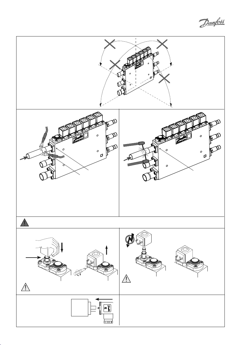
Mounting: With coils upwards
CTM Multi Ejector needs to be fixed to the
rack frame using 4 holes in the aluminum
block do avoid stress on the connectors
Brazing Welding
Danfoss
32F876.10
N
2
Danfoss
032F842.11
N
2
Max. 75 °C / 167 °F
Max. 700 °C / 1300 °F
Recommendation for brazing
Recommendation: brazing nozzle 4 - 6 mm ( 5/32 in - 15/64 in)
Materials used for brazing:
• Flux: Metalli tenacity No. 5 Powder or Braze Tec
special h paste.
• Filler: Silver-Flo 55 (BS:AG 14/ DIN L-Ag55 Sn) or Silver-Flo
56 (AWS B Ag-7).
Recommendation for TIG welding
• Power approximately 60 A.
• Use Shield gas charge - Argon.
• Material for welding - approximately
2 mm thick stainless steel alloy.
Warnin g: Filler metals containing Phosphor i.e. BS: CP 1/ DIN L-Ag 15P or BS: CP 3/ DIN L-Ag P7 must not be used.
Coil
On Off
Click!
Danfoss
Danfoss
Warning
Be sure that the O-ring is in place.
32F1002.10
Mounting D IN plug / LED DIN plug.
© Danfoss | DCS (rm) | 2019.11
Danfoss
32F1004.10
Armature tubes are sensitive and have to be protected
during the installation:
• do not damage the armature tubes with strokes or
forces
• do not lift or handle the block by lifting the armature
tubes etc.
• avoid pull-forces on the wires connected to the coils
32F882.10
Warning
Never switch on power to the coil when it is
dismounted from the valve. There is a danger the coil
may be damaged and a risk of injuries and burns.
DKRCC.PI.VM0.A2.02 | 2
Danfoss
032F841.11
Max. 75 °C / 167 °F
Danfoss
32F1004.10
Page 3

Starting up /Operation:
Opening sequence:
1 - connector A
2 - connector C
3 - connector E
Follow the opening sequence to avoid too
high NRV differential pressure.
Service
Mounting and service of ejectors
Liquid ejectors* and then high pressure
ejectors with the highest capacities (longest
ejectors) must be placed closest to the suction
connector C.
Any blank ejector must be placed closest to
the suction connector C.
*aplicable only for CTM 6 Combi
For mounting of pressure transmitter
MBS 8250 (064G1136)
B
Starting up the system: open all connection ball valves slowly
(avoiding liquid hammer that can damage
internal check valve (NRV) and build-in strainer.
It is mandatory to clean the strainer after 2 days of running the
system. O-rings needs to be replaced with the two new ones placed
on the strainer top. Removed O-rings to be placed on the strainer
top and reused after return to initial shape during next strainer
maintenance. Strainer cleanliness is important for proper operation
of Multi Ejector and the cleaning shall be repeated if necessary every
2-3 weeks to remove the dirt circulating in the system.
A: Inlet connector
Gas cooler outlet - Ball valve - inlet connector
Combi brazing
B: Inlet measurement port G
C: Suction connector
MT evaporator outlet - Ball valve - suction connector
Combi brazing
D: Suction measurement port G
E: Outlet connector
Outlet connector - Ball valve - Receiver
Combi brazing 1 inch ODF - weld 1
F: Outlet measurement port G
Pressure transmitter connections
A
AB
7
/8 inch ODF - weld 3/4 inch (EN10220)
7
/16 inch - 20 UNF
7
/8 inch ODF- weld 3/4 inch (EN10220)
7
/16 inch - 20 UNF
1
7
/8 inch (EN10220)
/16 inch - 20 UNF
D
Warning:
C
EF
C
Danfoss
32F880.10
Pressure transmitter
Type MBS 8250
Ratiometric
Pin 1 (A): + supply
Pin 2 (B): - supply/common
Pin 3 (C): output
Do not disassemble / assemble the parts unnecessarily to avoid risk of breaking the O-ring, dirt in the valve etc.
Insulation of Multi Ejector
Requirements for materials used for insulation:
• has to be based on a synthetic rubber base
or ex Polyurethane
• water vapor diffusion resistance number μ
≤7000
Exchange of connectors
and pressure transmitters
A
D
Tightening sequence
Torque 6 mm screws: 10 Nm ± 1 Nm
Allen key 5 mm
Torque 6 mm screws: 10 Nm ± 1 Nm
Allen key 5 mm
Torque 8 mm screws: 27.5 Nm ± 2.5 Nm
Allen key 6 mm
© Danfoss | DCS (rm) | 2019.11
C
B
• thermal conductivity ≤ 0,033 W/(m·K)
• insulations material thickness ≥ 5 mm
• for use at low temperature -10°C or lower
• for use at high temperature +50°C or higher
• glue or adhesive made of Poly chloroprene or it is Silicone type
Do not insulate the coils of Multi Ejector
Torque for mounting
pressure transmitters
32,5 Nm ± 2,5
Wrench 22 mm
oss
Danf
32F1000.10
DKRCC.PI.VM0.A2.02 | 3
Page 4

Service
= compressor oil
B
B
C
Danfoss
32F855.10
D
A
Tightening sequence
8
Mount the strainer
with screws
C
Danfoss
D
A
Tightening sequence
32F877.20
Mount the ejector with screws
Allen key 5 mm
Torque 10 Nm ± 1
Oil O-rings and place
strainer in valve
Allen key 5 mm
Torque 10 Nm ± 1
7
Oil O-rings and place ejector
5 mm allen key
Torque 6 Nm ± 1
6
Assemble strainer
5
5 mm
allen key
3
Allen key 5 mm
Service on strainer
© Danfoss | DCS (rm) | 2019.11
Clean or replace strainer
and replace O-ring
4
Dismount strainer
3
2
2
1
1
Remove strainer
from valve body
Allen key 5 mm
Remove ejector from valve body Replace complete ejector
Servi ce on ejector
DKRCC.PI.VM0.A2.02 | 4
 Loading...