

Page 1

Data Sheet
CTM High pressure valve
Type CTM 6
Improves COP and lowers swept volume of the MT compressors in CO2 systems with parallel compressors
Danfoss Multi Ejector SolutionTM, consists of a
CTM 6 High Pressure valve and an AK-PC 782A
controller. This solution makes CO2 refrigeration
systems economically competitive with the
HFC systems at all ambient temperatures by
improving COP in comparison to standard
parallel compressor systems.
CO2 systems with Multi Ejector SolutionTM can
be installed in any climate delivering lower
energy consumption than i.e. R404A. It
removes the CO2 equator entirely.
CTM 6 HP is designed for CO2 systems with
parallel compression to lift a part of the gas
from MT suction and mix it with the gas coming
from the gas cooler at medium pressure level.
AI260946128833en-000601
Page 2
Pressure
Danfoss
32F996.12
P
H
P
L
P
S
P
D
P
H
P
D
P
L
P
S
1
2 3
4 5
6
7
1234567
Nozzle
Throat
Exit
Mixing chamber
Diuser
Intake due to pressure dierential
Pressure increase due to reducing ow velocity
CTM High pressure valve, type CTM 6
Features
First Cost savings
• Lower cost compared to parallel compression transcritical CO2 packs due to lower swept volume of compressors.
(i.e. smaller compressors or less number of compressors).
• Reliable and robust design.
• Fully integrated solution not requiring any additional components like check valves or motorized ball valves.
• Fully serviceable - wide range of spare parts and accessories.
• Easily accessible strainer / lter for fast maintenance.
• Brings rst cost savings.
◦ High pressure valve becomes redundant
◦ Enables 15 - 35 % savings on compressor swept volume, compared to booster systems.
Fast Pay Back – Energy saving
• Improved COP, enhanced operation of parallel compressors and lower swept volume to the MT compressors ,
resulting in lower energy consumption.
• Savings for end users
• Fast payback – lower energy consumption
◦ Less compressors and higher eciency on the systems, leads to payback time of less than 2 years on avarage
globally.
• The combination of CTM 6 High Pressure and the AK-PC 782A ensure an easy setup and commissioning, robust
control of the system that ensures many years of problem free operation.
Functions
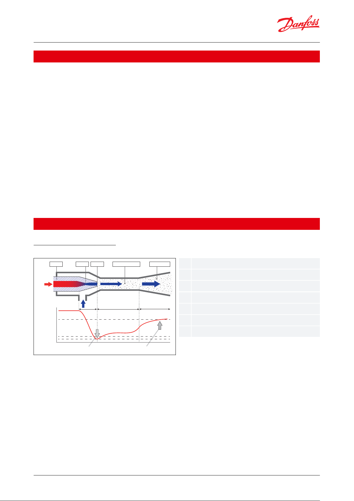
The Multi Ejector function
Figure 1: The Multi Ejector function
An ejector is a device that uses expansion energy to compress another uid. In this case with the transcritical system
there is up to 20% of the compressor work that can theoretically be recovered in the expansion.
In this case with the Multi Ejector system the work is coming from the CO2 leaving the gas cooler. The high pressure
CO2(PH) is entering the nozzle where the expansion is taking place. At the exit of the nozzle the speed is very high
and as a consequence of that the pressure is low.
This low pressure is used to drag liquid from the MT suction accumulator (PL). From there the two ows are mixed in
the mixing chamber where the pressure will be lower than at the drive inlet due to the mixing of vapour from a
higher pressure.
After the mixing the ow enters the diuser where the ow is slowed down. The shape of the diuser enables the
conversion from kinetic energy (velocity) to potential energy (pressure). After the diuser the ow is returned to the
receiver.
© Danfoss | Climate Solutions | 2021.03 AI260946128833en-000601 | 2
Page 3
AK-PC 782A
AKVH
Gas cooler
Liquid
receiver
Medium temp. load
Low temp. load
Danfoss
AKS 11
MBS 8250
MBS 8250
MBS 8250
AKS 11
AKS 11
AK-CC 550A
AKS 11
AKS 11
FC 103
AKS 11
AKS 32R
AK-CC 550A
FC 103
IT MT
AKVH
AKS 11
DGS
CCMT
(ICMTS)
FC 103
MBS
8250
Multi Ejector High Pressure
LT
AKS 32R
AK-SM 8XX/
AK-SM 720/
AKS 21A
HP High Pressure (120-140 bar Max working pressure)
HP Receiver Pressure (60-90 bar Max working pressure)
LP Suction Pressure MT (35-55 bar Max working pressure)
LP Suction Pressure LT (25-30 bar Max working pressure)
CTM High pressure valve, type CTM 6
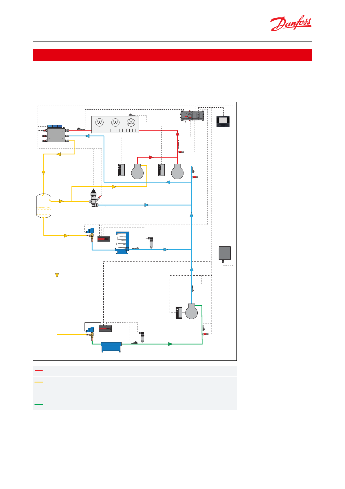
Applications
The Multi Ejector is designed to lift a part of the gas from MT suction and mix it with the gas coming from the gas
cooler at medium pressure level. Pre-compressed gas is taken from the receiver to parallel compressor which works
more eciently due to lower pressure lift required.
Figure 2: Application
© Danfoss | Climate Solutions | 2021.03 AI260946128833en-000601 | 3
Page 4
0
1000
2000
3000
4000
5000
6000
7000
30
40 50
60
70 80 90 100
110 120 130
Y
X
HP 1875
HP 3875
Danfoss
32F866.10
XYInlet pressure HP side [Bar]
Mass ow HP side [kg/hr]
Refrigerant
R744 with oil
Maximum working pressure
140 bar / 2031 psi
Max. test pressure
1.43 x 140 bar / 1.43 x 2031 psi
Max. OPD
90 bar / 1305 psi (for single-voltage coil, 50 Hz)
Min. OPD
< 0.1 bar / 1.45 psi
Max. pres. dif. E and C connections
20 bar / 290 psi
Media temp. range
-10 °C – +50 °C / +14 °F – 122 °F
Ambient temp. range
-10 °C – +50 °C / +14 °F – 122 °F
Humidity
0 − 100% R.H. (0-97% R.H. non-condensation condition if IP level is below IPX5)
CTM High pressure valve, type CTM 6
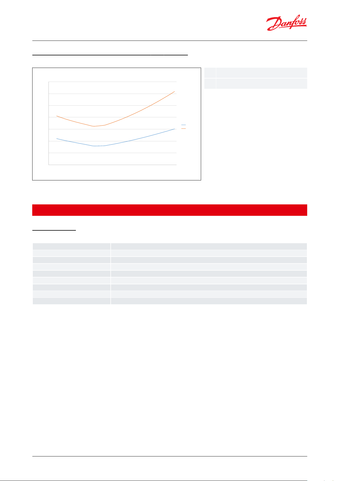
High pressure lift ejectors design mass ow HP side
Figure 3: High pressure lift ejectors design mass ow HP side
Flow from the high pressure side (motive ow) for fully open ejector block as a function of temperature out of gas
cooler.
Media
Technical data
Table 1: Technical data
© Danfoss | Climate Solutions | 2021.03 AI260946128833en-000601 | 4
Page 5
Housing
Aluminium AW-6082 T6
Connections
Stainless steel AISI 304
Ejectors
Brass
Screws
Stainless steel A2-70
Danfoss
32F871.12
45 mm / 1.77 inch
192.5 mm / 7.6 inch
60 mm / 2.36 inch
90 mm / 3.54 inch
Ø 8.5 mm /
0.34 inch
250.7 mm / 9.9 inch
176 mm / 6.9 inch
106 mm / 4.2 inch
29 mm /
1.14 inch
47.3 mm / 1.86 inch
423.5 mm / 16.7 inch
287 mm / 11.3 inch
64 mm /
2.5 inch
200 mm / 7.9 inch
A
C
EF
D
B
(pgc)
(p0)
(p
rec
)
G
H
J
I
1
I
2I3
I4I
5
I
6
J
J
K
L
M
CTM High pressure valve, type CTM 6
Product specication
Material specication
Table 2: Material specication
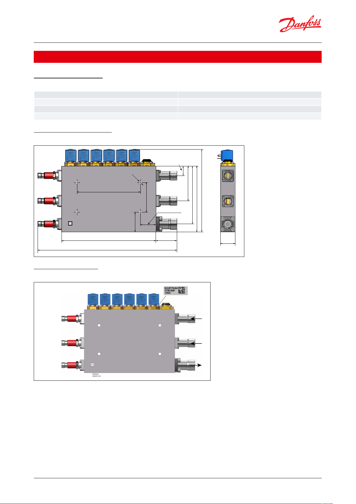
Dimensions and weights
Figure 4: CTM 6(Weight: 9.1 Kg / 20.1 lb)
Connector positions
Figure 5: Connector positions
© Danfoss | Climate Solutions | 2021.03 AI260946128833en-000601 | 5
Page 6

S
E1
E2
E3
E4
E5
E6
Danfoss
32F870
ESEjector
Strainer
ABCDE
FGHIJKL
M
Gas cooler outlet - Ball valve - inlet connector
Combi brazing 7/8 inch ODF - weld 3/4 inch
(EN10220)
Inlet measurement port G 7/16 inch - 20 UNF
Suction connector. MT evaporator outlet - Ball
valve - suction connector.
Combi brazing 7/8 inch ODF - weld 3/4 inch
(EN10220)
Suction measurement port G 7/16 inch - 20 UNF
Common outlet connector - Ball valve - Receiver
Combi brazing 1 inch ODF - weld 11/8 inch
(EN10220)
Outlet measurement port G 7/16 inch - 20 UNF
Strainer
Label
Ejector
Pressure transmitter MBS 8250 (064G1136)
High pressure inlet
Suction inlet
Receiver
Type
Code no.
Product name
Ejector 1
Ejector 2
Ejector 3
Ejector 4
Ejector 5
Ejector 6
CTM 6
032F5673
CTM Multi Ejec-
tor HP 1875
CTM EHP 125
CTM EHP 250
CTM EHP 500
CTM EHP 1000
Blank ejector
Blank ejector
CTM 6
032F5698
CTM Multi Ejec-
tor HP 2875
CTM EHP 125
CTM EHP 250
CTM EHP 500
CTM EHP 1000
CTM EHP 1000
Blank ejector
CTM 6
032F5674
CTM Multi Ejec-
tor HP 3875
CTM EHP 125
CTM EHP 250
CTM EHP 500
CTM EHP 1000
CTM EHP 1000
CTM EHP 1000
CTM High pressure valve, type CTM 6
Mounting order of ejectors:
Ejectors with the highest capacities (longest ejectors) must be placed closest to the suction connector C.
Any blank ejector should be placed after the ejectors.
Ordering
Valve conguration
Figure 6: Valve conguration
Table 3: Valve conguration
© Danfoss | Climate Solutions | 2021.03 AI260946128833en-000601 | 6
Page 7

1.2.1.
2.
CTM 6 HP 1875
CTM 6 HP 2875
CTM 6 HP 3875
Type
Capacity - Mass ow
(1)
Capacity - Mass ow
(2)
Code no. Single pack
[kg/h]
[lb/h]
CTM 6 HP 1875
1875
4134
032F5673
CTM 6 HP 2875
2875
6340
032F5698
CTM 6 HP 3875
3875
8543
032F5674
Image
Part
Type
Capacity - HP Mass
ow 1
Description
Code no. Single
pack
[kg/h]
[lb/h]
Ejectors
CTM EHP 125
125
275.5
1. Completely assembled ejector with O-rings
already mounted
032F9102
CTM EHP 250
250
551
1. Completely assembled ejector with O-rings
already mounted
032F9103
CTM EHP 500
500
1102
1. Completely assembled ejector with O-rings
already mounted
032F9104
CTM EHP 1000
1000
2204
1. Completely assembled ejector with O-rings
already mounted
032F9105
CTM Blank ejector
–
–
1. Completely assembled blank ejector with Orings already mounted
032F9112
Image
Part
Type
Description
Code no. Single pack
X 1
X 2
X 2
X 6
Strainer
CTM strainer
Mesh only
2 sets of 2 O-rings
032F9113
O-rings
CTM O-rings
2 sets of 2 O-rings for strainer
6 sets of 3 O-rings for ejectors
032F9114
Connectors
DN 20
Connector + O-ring
032F9116
DN 25
Connector + O-ring
032F9117
CTM High pressure valve, type CTM 6
Multi Ejector
Table 4: Multi Ejector
Table 5: Multi Ejector CTM 6
(1)
(1)
R744 at 90 bar / 35 °C
R744 at 90 bar / 35 °C
(2)
(2)
R744 at 1305 psi /95 °F
R744 at 1305 psi /95 °F
(HP = High Pressure lift)
(The above code numbers are without coils which should be ordered separately – see coil ordering below).
Accessories
Spare parts
Table 6: Ejectors
Table 7: Strainer, O-rings and connectors
© Danfoss | Climate Solutions | 2021.03 AI260946128833en-000601 | 7
Page 8

Image
Part
Type
Description
Code no.
Pressure transmitter
MBS 8250
Pressure transmitter with Oring
064G1136
Cable
–
10 meter cable for pressure
transmitter
064G0950
Image
Type
Voltage
Frequency / Power consumption
Code no. Single
pack
[V]
[Hz]
[W]
[Hz]
[W]
with DIN plug
(1)
AS230CS
230508607
042N7601
AZ120CS
110 - 120508.5607
042N4202
Image
Type
Voltage [V]
Frequency
Code no. Single pack
DIN plug (LED)
230
50 / 60
042N0265
(1)
DIN plug
Max. 250
50 / 60
042N0156
CTM High pressure valve, type CTM 6
Table 8: Pressure transmitter and Cable
Coils
Table 9: DIN spade connection
(1)
(1)
The three pins on the coil can be tted with spade tabs, 6.3 mm wide (to DIN 46247). The two current carrying pins can also be tted with
The three pins on the coil can be tted with spade tabs, 6.3 mm wide (to DIN 46247). The two current carrying pins can also be tted with
spade tabs, 4.8. mm wide. Max. lead cross section: 1.5 mm2. Voltage variation: V AC -15% - 10%, If DIN plug is used (DIN 43650) the leads must
spade tabs, 4.8. mm wide. Max. lead cross section: 1.5 mm2. Voltage variation: V AC -15% - 10%, If DIN plug is used (DIN 43650) the leads must
be connected in the socket. The socket is tted with a Pg 11 screwed entry for 6 – 12 mm.
be connected in the socket. The socket is tted with a Pg 11 screwed entry for 6 – 12 mm.
Plug for DIN spade connection
Table 10: Plug for DIN spade connection
(1)
(1)
Only for AS230CS
Only for AS230CS
Controller AK-PC 782A
Danfoss oers a wide range of market leading Pack Controllers. Being the ag ship and best in class controller for
transcritical CO2 packs controls, the AK-PC 782A oers the highest possible eciency with the Multi Ejector, CTM.
The complete application control features:
• Complete booster pack control of up to 3 suction groups (max. 12 compressors) and high pressure system
• Signicant savings with heat recovery for Tap Water and heat reclaim
• Extensive control of oil ow and pressurization
• Best in class safety monitoring and fail-safe functions
• Minimal energy consumption while ensuring optimal food quality
• Auto-congured, easy-to-use graphical representation with Danfoss System Manager
• Independent, customised control and monitoring of auxiliary function
© Danfoss | Climate Solutions | 2021.03 AI260946128833en-000601 | 8
Page 9

CTM High pressure valve, type CTM 6
Temperature sensors and pressure transmitters
Danfoss oers a comprehensive range of sensors for temperature and pressure sensors developed to meet the
requirements of the entire pack application.
The sensor range delivers the following key features and benets:
• Long term reliability minimize system downtime.
• Robust construction protects against mechanical shock and vibration.
• Temperature sensor design ensures fast response time and precise measurement.
• Hermetically sealed pressure element ensures no leakage.
• Pressure transmitter output calibrated for perfect t to the application.
• Pulse snubber ensures protection against liquid hammering, cavitation or pressure peaks.
Disclaimer
WARNING:
The CTM Multi Ejector valve is approved for use only with Danfoss pack controller type AK-PC 78x.
Danfoss expressly disclaims, and any responsibility or liability, whether based on contract, breach of warranty, tort,
statute or otherwise, shall be excluded, if the CTM Multi Ejector valve is used with any controller other than a
Danfoss controller type AK-PC 78x.
For further information on AK-PC, please see separate document.
© Danfoss | Climate Solutions | 2021.03 AI260946128833en-000601 | 9
Page 10

File name
Document type
Document topic
Approval authority
032F9627.AA
Manufacturers Declaration
PED
Danfoss
UL SA45046
Mechanical - Safety Certicate
-
UL
CTM High pressure valve, type CTM 6
Certicates, declarations, and approvals
The list contains all certicates, declarations, and approvals for this product type. Individual code number may have
some or all of these approvals, and certain local approvals may not appear on the list.
Some approvals may change over time. You can check the most current status at danfoss.com or contact your local
Danfoss representative if you have any questions.
Table 11: Certicates, declarations, and approvals
Coils:
AS230CS: LLC CDC TYSK; The Low Voltage Directive 2014/35/EU (LVD);
Electromagnetic Compatibility Directive 2014/30/EU (EMC)
AZ120CS: C UR US; LLC CDC TYSK; The Low Voltage Directive 2014/35/EU (LVD);
Electromagnetic Compatibility Directive 2014/30/EU (EMC)
© Danfoss | Climate Solutions | 2021.03 AI260946128833en-000601 | 10
Page 11

Online support
Danfoss oers a wide range of support along with our products, including digital product information, software,
mobile apps, and expert guidance. See the possibilities below.
The Danfoss Product Store
The Danfoss Product Store is your one-stop shop for everything product related—no matter where
you are in the world or what area of the cooling industry you work in. Get quick access to essential
information like product specs, code numbers, technical documentation, certications, accessories,
and more.
Start browsing at store.danfoss.com.
Find technical documentation
Find the technical documentation you need to get your project up and running. Get direct access to
our ocial collection of data sheets, certicates and declarations, manuals and guides, 3D models
and drawings, case stories, brochures, and much more.
Start searching now at www.danfoss.com/en/service-and-support/documentation.
Danfoss Learning
Danfoss Learning is a free online learning platform. It features courses and materials specically
designed to help engineers, installers, service technicians, and wholesalers better understand the
products, applications, industry topics, and trends that will help you do your job better.
Create your Danfoss Learning account for free at www.danfoss.com/en/service-and-support/learning.
Get local information and support
Local Danfoss websites are the main sources for help and information about our company and
products. Find product availability, get the latest regional news, or connect with a nearby expert—all
in your own language.
Find your local Danfoss website here: www.danfoss.com/en/choose-region.
Coolselector®2 - nd the best components for you HVAC/R system
Coolselector®2 makes it easy for engineers, consultants, and designers to nd and order the best
components for refrigeration and air conditioning systems. Run calculations based on your operating
conditions and then choose the best setup for your system design.
Download Coolselector®2 for free at coolselector.danfoss.com.
Danfoss can accept no responsibility for possible errors in catalogues, brochures and other printed material. Danfoss reserves the right to alter its
products without notice. This also applies to products already on order provided that such alterations can be made without subsequential
changes being necessary in specications already agreed. All trademarks in this material are property of the respective companies. Danfoss and
the Danfoss logotype are trademarks of Danfoss A/S. All rights reserved.
© Danfoss | Climate Solutions | 2021.03 AI260946128833en-000601 | 11
 Loading...