

Page 1
Data sheet
Data sheet
CLP / CLP D pumps
CLP 674 pumps /
CLP 674 / CLP D 674-025-058 /
085-152 / 140-500
CLP D 674 pumps /
CLP S 674 pumps
oilandgas.danfoss.com
hpp.danfoss.com
Page 2

Data sheet CLP 674 / CLP D 674
Table of Contents
Contents
1. Introduction ............................................................................2
2. Benets.................................................................................3
3. Application examples ...................................................................3
4. Technical data ..........................................................................4
4.1 CLP 674-025-058 .......................................................................4
4.2 CLP D 674-025-058 .....................................................................5
4.3 CLP 674-085-152 ........................................................................6
4.4 CLP D 674-085-152 ......................................................................7
4.5 CLP 674-140-500 ........................................................................8
4.6 CLP D 674-140-500 ......................................................................9
5. Pressure and ow ......................................................................10
5.1 CLP 674 / CLP D 674-0025-058 typical ow curves at 80 barg (1,160 psig) pressure .......11
5.2 CLP 674 / CLP D 674-085-152 typical ow curves at 80 barg (1,160 psig) pressure .........12
5.3 CLP 674 / CLP D 674-140-500 typical ow curves at 80 barg (1,160 psig) pressure .........13
5.4 CLP 674/ CLP D 674-025-500 typical NPIPr curves........................................14
6. Motor requirements....................................................................16
7. Installation.............................................................................16
7.1 Filtration...............................................................................17
7.2 Noise ..................................................................................17
8. Service.................................................................................18
8.1 Spare parts ............................................................................18
8.2 Spare part suitcase .....................................................................18
9. Dimensions and connections...........................................................19
9.1 CLP 674 / CLP D 674-025-058 pump.....................................................19
9.2 CLP 674 / CLP D 674-085-152 pump .....................................................20
9.3 CLP 674 / CLP D 674-140-500 pump . . . . . . . . . . . . . . . . . . . . . . . . . . . . . . . . . . . . . . . . . . . . . . . . . . . . .21
10. Pump and bell-housing ................................................................22
11. Pump base plate solution ..............................................................23
1. Introduction
CLP 674 / CLP D 674 pumps are specic designed
for various chemicals, liquids, additives and other
hard-to-handle uids in production systems,
placed in subsea, onshore and oshore applications.
Danfoss CLP pumps are based on the axial piston
principle oering long life and high eciency in
the demanding oil and gas industry. The Danfoss
CLP pumps have a light and compact design,
resulting in one of the smallest footprints on the
market.
All parts are designed to provide long service
life, i.e. long service life with a constantly high
eciency and minimum of service required.
Lubrication of the moving parts in the pumps is
This datasheet covers CLP 674, CLP D 674-025058 / 085-152 / 140-500. In the next pages all
pumps will be named as CLP.
The CLP 674 and CLP D 674 pumps are all
engineered according to API 674. The CLP pumps
provided by the uid itself. No oil lubrication is
thus required.
The pumps are xed displacement pumps in
which the ow is proportional to the number of
revolutions of the input shaft and the pump
displacement, regardless of any counterpressure.
The pump design ensures a minimal acceleration
loss and low pulsation.
If magnetic drive is required, please
contact Danfoss High Pressure Pumps
sales organization for further information.
are made in AISI 316, whereas the CLP D are made
in Super Duplex / Duplex.
2
521B1320 / DKCFN.PD.014.M3.02 / 01.2016
Page 3
Data sheet CLP 674 / CLP D 674
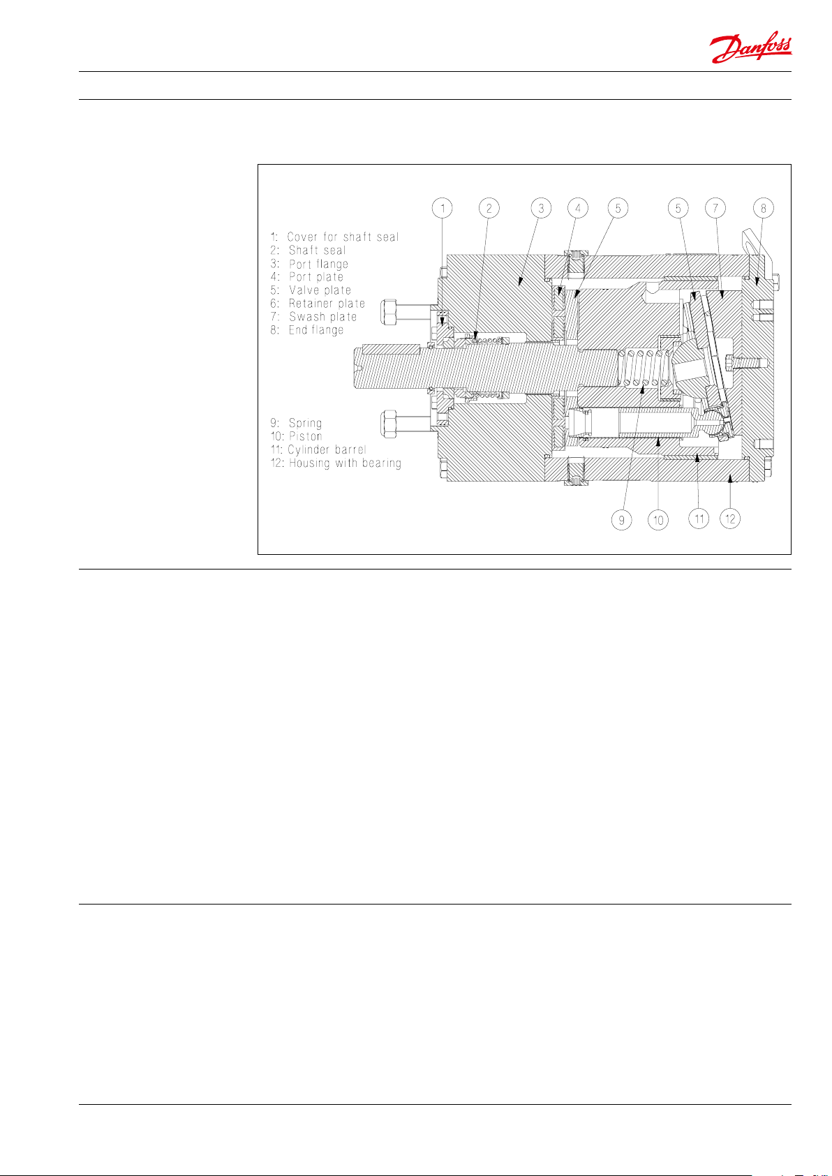
Below sectional drawing is an example of a CLP 674 / CLP D 674-025-500
2. Benets
• High reliability:
• Constructed to provide maximum
reliability.
• Designed for a wide range of corrosive,
volatile and other hard-to-handle
uids.
• All parts are made of high-grade
materials.
• Minimum service required:
• Generates insignicant pulsations in
the discharge line.
• No oil lubrication is required.
• Long service life and easy maintenance.
• Low energy costs:
• The highly ecient axial piston design
provides the lowest energy consumption
of any comparable on the market.
• Zero risk of lubricant contamination:
• Oil lubricants are replaced with the
pumped medium so there is no
contamination risk from the pump.
3. Application examples • Dehydration / glycol pumping
• Transfer pumps
• Produced water injection
• Wash water system
• Chemical / technical processes
• Water make up pump
• Easy installation:
• One of the smallest, lightest and most
compact designs available in the
market.
• Pump can be installed horizontally or
vertically.
• In most cases no pulsation dampeners
are necessary due to extremely low
pulsations.
• Powered by electric motors or
combustion engines.
• Certied quality:
• ATEX available on request.
• CE available.
• Type approval available.
• Design verication available on
request.
• The pump is designed according to API
674.
• Gas sweeting – “Amine”
• Water and glycol hydraulic uid
• Subsea
• Closed and open drain pump
• Seal ush pump
•
521B1320 / DKCFN.PD.014.M3.02 / 01.2016
3
Page 4
Data sheet CLP 674 / CLP D 674
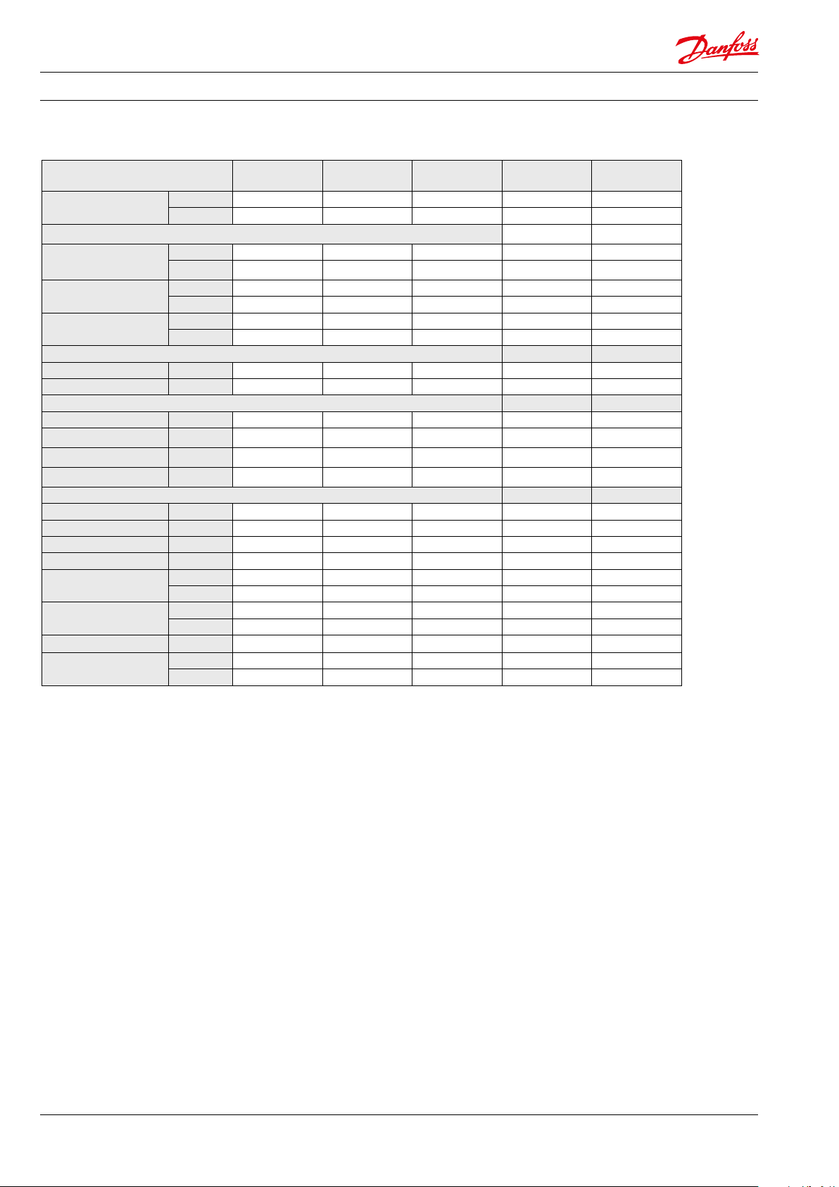
4. Technical data 4.1 CLP 674-025-058
Pump size CLP 674-025 CL P 674- 035 CLP 674- 042 CLP 674-050 CLP 674-058
Geometric
displacement
Pressure
1)
Min. continuous
outlet pressure
Max. continuous
inlet pressure [MASP]
Max. continuous
outlet pressure [MAWP]
3)
Speed
Min. speed rpm 700 700 700 700 700
Max. speed
5)
Typical ow at 80 barg - Flow curves available in section 5
150 0 rpm l/min 12.0 0 16.09 20.86 24.43 28.69
3000 rpm l/min 26 .11 34.30 43.84 50.98 59.50
1800 r pm gpm 3.91 5. 21 6.73 7.86 9.21
3600 rpm gpm 8.39 10.98 14.01 16 .27 18.97
Typical motor size at 80 barg
150 0 rpm kW 50Hz 3 3 4 5.5 5.5
1800 r pm hp 60Hz 5 5 7.5 7. 5 10
3000 rpm kW 50Hz 5.5 7.5 7.5 11 11
3600 rpm hp 60Hz 7.5 10 15 15 20
Media temperature
Ambient temperature
Sound pressure level
Weight
cm³/rev 9.41 12.14 15. 32 17.70 20.54
in³/rev 0.57 0.74 0.93 1.08 1.25
barg 20 20 20 20 20
psig 290 290 290 290 290
barg 10 10 10 10 10
2)
psig 145 145 145 145 145
barg 175 175 175 171 157
6)
psig 2538 2538 2538 2480 2277
rpm 3600 3600 3600 3600 3600
o
C 0 – 95 0 – 95 0 – 95 0 – 95 0 – 95
o
F -17 – 203 -17 – 203 -17 – 203 -17 – 203 -17 – 203
o
C -45 – 60 -45 – 60 -45 – 60 -45 – 60 -45 – 60
o
F -42 – 140 -42 – 140 -42 – 140 -42 – 140 -42 – 140
4)
dB(A) 79 79 79 79 79
kg 16 16 16 16 16
lbs 35 35 35 35 35
1)
For lower and higher continuous pressure please contact Danfoss High Pressure Pumps.
2)
NPIPr - see section 5.
3)
For lower or higher continuous speed please contact Danfoss High Pressure Pumps.
4)
According to ISO 3744 : 2010.
5)
Over 3000 rpm, the pump operation is referred to as “high end performance”, max. outlet
pressure is limited to 140 bar. Recommended inspection intervals are detailed in section 8.
6)
Over 160 barg, the pump operation is referred to as “high end perfomance” and recommended
inspection intervals are detailed in section 8.
4
521B1320 / DKCFN.PD.014.M3.02 / 01.2016
Page 5
Data sheet CLP 674 / CLP D 674
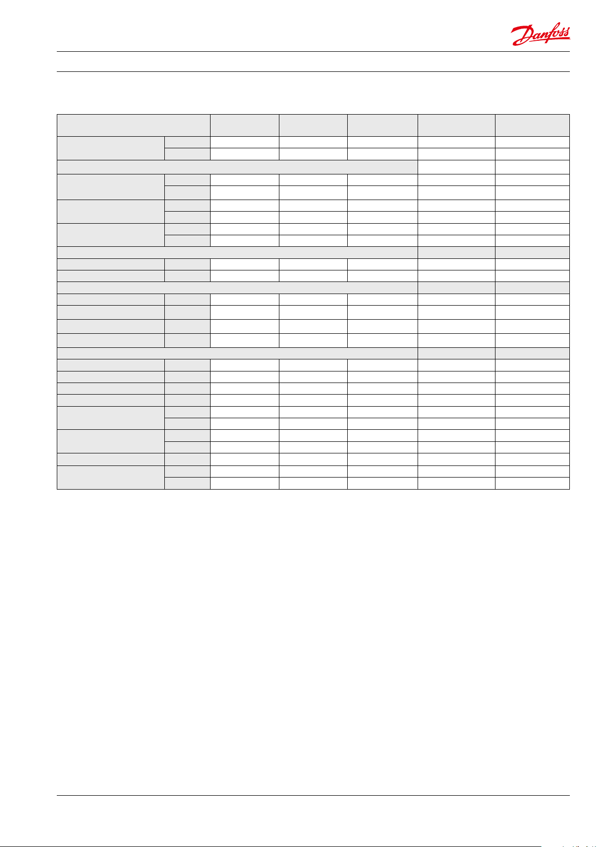
4.2 CLP D 674-025-058
Pump size CLP D 674-025 CLP D 674-035 CLP D 674-042 CLP D 674-050 CLP D 674-058
Geometric
displacement
Pressure
1)
Min. continuous
outlet pressure
Max. continuous
inlet pressure [MASP]
Max. continuous
outlet pressure [MAWP]
3)
Speed
2)
6)
Min. speed rpm 700 700 700 700 700
Max. speed
5)
Typical ow at 80 barg - Flow curves available in section 5
150 0 rpm l/min 12.00 16.09 20.86 24.43 28.69
3000 rpm l/min 2 6.11 34.30 43.84 50.98 59.50
1800 r pm gpm 3.91 5.21 6.73 7. 86 9.21
3600 rpm gpm 8.39 10.98 14. 01 16.27 18.97
Typical motor size at 80 barg
150 0 rpm kW 50Hz 3 3 4 5.5 5.5
1800 r pm hp 60Hz 5 5 7. 5 7.5 10
3000 rpm kW 50Hz 5.5 7. 5 7.5 11 11
3600 rpm hp 60Hz 7.5 10 15 15 20
Media temperature
Ambient temperature
Sound pressure level
4)
Weight
cm³/rev 9.41 12.14 15. 32 17.7 0 20.54
in³/rev 0.57 0.74 0.93 1.08 1.25
barg 20 20 20 20 20
psig 290 290 290 290 290
barg 10 10 10 10 10
psig 145 145 145 145 145
barg 230 205 186 171 157
psig 3335 2973 2697 2480 2277
rpm 3600 3600 3600 3600 3600
o
C 0 – 95 0 – 95 0 – 95 0 – 95 0 – 95
o
F -17 – 203 -17 – 203 -17 – 203 -17 – 203 -17 – 203
o
C -45 – 60 -45 – 60 -45 – 60 -45 – 60 -45 – 60
o
F -42 – 140 -42 – 140 -42 – 140 -42 – 140 -42 – 140
dB(A) 79 79 79 79 79
kg 16 16 16 16 16
lbs 35 35 35 35 35
1)
For lower and higher continuous pressure please contact Danfoss High Pressure Pumps.
2)
NPIPr - see section 5.
3)
For lower or higher continuous speed please contact Danfoss High Pressure Pumps.
4)
According to ISO 3744 : 2010.
5)
Over 3000 rpm, the pump operation is referred to as “high end performance”, max. outlet
pressure is limited to 140 bar. Recommended inspection intervals are detailed in section 8.
6)
Over 160 barg, the pump operation is referred to as “high end perfomance” and recommended
inspection intervals are detailed in section 8.
521B1320 / DKCFN.PD.014.M3.02 / 01.2016
5
Page 6
Data sheet CLP 674 / CLP D 674
4.3 CLP 674-085-152
Pump size
Geometric
displacement
Pressure
1)
Min. continuous
outlet pressure
Max. continuous
inlet pressure [MASP]
Max. continuous
outlet pressure
3)
Speed
CLP 674-085
CLP 674-105
cm³/rev 50 63 70 80 90
in³/rev 3.05 3.86 4.29 4.88 5.49
barg 10 10 10 10 10
psig 145 145 145 145 145
barg 10 10 10 10 10
2
psig 145 145 145 145 145
barg 160 159 151 144 132
psig 2320 2305 219 0 2089 1915
CL P 674 -115
CL P 674 -137
CL P 674 -152
Min. speed rpm 700 700 700 700 700
Max. speed rpm 1800 1800 1800 1800 1800
Typical ow at 80 barg - Flow curves available in section 5
1000 rpm l/min 46 58 65 75 84
150 0 rpm l/min 70 87 97 112 125
120 0 rp m gpm 15 18 21 24 27
1800 r pm gpm 22 28 31 36 40
Typical motor size at 80 barg
150 0 rpm kW 50Hz 18 .5 18 .5 22 30 30
1800 r pm hp 60Hz 21 21 25 25 35
o
Media temperature
Ambient temperature
Sound pressure level
Weight
C 0 – 95 0 – 95 0 – 95 0 – 95 0 – 95
o
F -17 – 203 -17 – 203 -17 – 203 -17 – 203 -17 – 203
o
C -45 – 60 -45 – 60 -45 – 60 -45 – 60 -45 – 60
o
F -42 – 140 -42 – 140 -42 – 140 -42 – 140 -42 – 140
4)
dB(A) 80 80 80 80 80
kg 40 40 40 40 40
lbs 88 88 88 88 88
1)
For lower and higher continuous pressure please contact Danfoss High Pressure Pumps.
2)
NPIPr - see section 5.
3)
For lower or higher continuous speed please contact Danfoss High Pressure Pumps.
4)
According to ISO 3744 : 2010.
6
521B1320 / DKCFN.PD.014.M3.02 / 01.2016
Page 7
Data sheet CLP 674 / CLP D 674
4.4 CLP D 674-085-152
Pump size
Geometric
displacement
Pressure
1)
Min. continuous
outlet pressure
Max. continuous
inlet pressure [MASP]
Max. continuous
outlet pressure
3)
Speed
cm³/rev 50 63 70 80 90
in³/rev 3.05 3.86 4.29 4.88 5.49
barg 10 10 10 10 10
psig 145 145 145 145 145
barg 10 10 10 10 10
2
psig 145 145 145 145 145
barg 160 159 151 144 132
psig 2320 2305 219 0 2089 1915
CLP
D 674-085
LP D 674-105
C
LP D 674-115
C
LP D 674-137
C
LP D 674-152
C
Min. speed rpm 700 700 700 700 700
Max. speed rpm 1800 1800 1800 1800 1800
Typical ow at 80 barg - Flow curves available in section 5
1000 rpm l/min 46 58 65 75 84
150 0 rpm l/min 70 87 97 112 125
120 0 rp m gpm 15 18 21 24 27
1800 r pm gpm 22 28 31 36 40
Typical motor size at 80 barg
150 0 rpm kW 50Hz 18 .5 18 .5 22 30 30
1800 r pm hp 60Hz 21 21 25 25 35
o
Media temperature
Ambient temperature
Sound pressure level
Weight
C 0 – 95 0 – 95 0 – 95 0 – 95 0 – 95
o
F -17 – 203 -17 – 203 -17 – 203 -17 – 203 -17 – 203
o
C -45 – 60 -45 – 60 -45 – 60 -45 – 60 -45 – 60
o
F -42 – 140 -42 – 140 -42 – 140 -42 – 140 -42 – 140
4)
dB(A) 80 80 80 80 80
kg 40 40 40 40 40
lbs 88 88 88 88 88
1)
For lower and higher continuous pressure please contact Danfoss High Pressure Pumps.
2)
NPIPr - see section 5.
3)
For lower or higher continuous speed please contact Danfoss High Pressure Pumps.
4)
According to ISO 3744 : 2010.
521B1320 / DKCFN.PD.014.M3.02 / 01.2016
7
Page 8
Data sheet CLP 674 / CLP D 674
4.5 CLP 674-140-500
Pump size
Geometric
displacement
Pressure
1)
Min. continuous
outlet pressure
Max. continuous
inlet pressure [MASP]
Max. continuous
outlet pressure
3)
Speed
CLP
674 -140
cm³/rev 127 165, 4 204 256 282 308 362 389 444
in³/rev 7,75 10,09 12,45 15.62 17. 21 18.8 22.09 23.74 2 7.1
barg 10 10 10 10 10 10 10 10 10
psig 145 145 145 145 145 145 145 145 145
barg 10 10 10 10 10 10 10 10 10
2
psig 145 145 145 145 145 145 145 145 145
barg 100 100 10 0 100 10 0 100 100 100 100
psig 1450 1450 1450 1450 1450 1450 1450 1450 1450
CLP
674 -185
CLP
674-230
CLP
674-290
CLP
674-320
CLP
674-350
CLP
674-400
CLP
674-440
CLP
674-5 00
Min. speed rpm 700 700 700 700 700 700 700 700 700
Max. speed
5)
rpm 1500 1500 1500 1500 1500 1500 1500 1500 1500
Typical ow at 80 barg - Flow curves available in section 5
1000 rpm l/min 107 145 184 236 262 292 348 370 428
900 rpm l/min 25 34 43 56 62 69 82 88 101
Typical motor size at 80 barg
1000 rpm kW 50Hz 22 30 37 45 45 55 75 75 75
900 rpm hp 60Hz 25 30 40 57 57 70 70 85 85
o
Media temperature
Ambient temperature
Sound pressure level
Weight
C 0 – 95 0 – 95 0 – 95 0 – 95 0 – 95 0 – 95 0 – 95 0 – 95 0 – 95
o
F -17 – 203 -17 – 203 -17 – 203 -17 – 203 -17 – 203 -17 – 203 -17 – 203 -17 – 203 -17 – 203
o
C -45 – 60 -45 – 60 -45 – 60 -45 – 60 -45 – 60 -45 – 60 -45 – 60 -45 – 60 -45 – 60
o
F -42 – 140 -42 – 140 -42 – 140 -42 – 140 -42 – 140 -42 – 140 -42 – 140 -42 – 140 -42 – 140
4)
dB(A) 85 85 85 85 85 85 85 85 85
kg 110 110 11 0 110 110 11 0 110 110 11 0
lbs 242 242 242 242 242 242 242 242 242
1)
For lower and higher continuous pressure please contact Danfoss High Pressure Pumps.
2)
NPIPr - see section 5.
3)
For lower or higher continuous speed please contact Danfoss High Pressure Pumps.
4)
According to ISO 3744 : 2010.
5)
Over 1200 rpm, the pump operation is referred to as “high end performance” and recommended inspection
intervals are detailed in section 8.
8
521B1320 / DKCFN.PD.014.M3.02 / 01.2016
Page 9

Data sheet CLP 674 / CLP D 674
4.6 CLP D 674-140-500
Pump size
Geometric
displacement
Pressure
1)
Min. continuous
outlet pressure
Max. continuous
inlet pressure [MASP]
Max. continuous
outlet pressure
3)
Speed
CLP D
674 -140
cm³/rev 127 165, 4 204 256 282 308 362 389 444
in³/rev 7,75 10,09 12 ,45 15. 62 17.21 18.8 22.09 23.74 2 7.1
barg 10 10 10 10 10 10 10 10 10
psig 145 145 145 145 145 145 145 145 145
barg 10 10 10 10 10 10 10 10 10
2
psig 145 145 145 145 145 145 145 145 145
barg 100 100 10 0 100 10 0 100 100 100 100
psig 1450 1450 1450 1450 1450 1450 1450 1450 1450
CLP D
674 -185
CLP D
674-230
CLP D
674-290
CLP D
674-320
CLP D
674-350
CLP D
674-400
CLP D
674-440
CLP D
674-5 00
Min. speed rpm 700 700 700 700 700 700 700 700 700
Max. speed
5)
rpm 1500 1500 1500 1500 1500 1500 1500 1500 1500
Typical ow at 80 barg - Flow curves available in section 5
1000 rpm l/min 107 145 184 236 262 292 348 370 428
900 rpm l/min 25 34 43 56 62 69 82 88 101
Typical motor size at 80 barg
1000 rpm kW 50Hz 22 30 37 45 45 55 75 75 75
900 rpm hp 60Hz 25 30 40 57 57 70 70 85 85
o
Media temperature
Ambient temperature
Sound pressure level
Weight
C 0 – 95 0 – 95 0 – 95 0 – 95 0 – 95 0 – 95 0 – 95 0 – 95 0 – 95
o
F -17 – 203 -17 – 203 -17 – 203 -17 – 203 -17 – 203 -17 – 203 -17 – 203 -17 – 203 -17 – 203
o
C -45 – 60 -45 – 60 -45 – 60 -45 – 60 -45 – 60 -45 – 60 -45 – 60 -45 – 60 -45 – 60
o
F -42 – 140 -42 – 140 -42 – 140 -42 – 140 -42 – 140 -42 – 140 -42 – 140 -42 – 140 -42 – 140
4)
dB(A) 85 85 85 85 85 85 85 85 85
kg 110 110 11 0 110 110 11 0 110 110 11 0
lbs 242 242 242 242 242 242 242 242 242
1)
For lower and higher continuous pressure please contact Danfoss High Pressure Pumps.
2)
NPIPr - see section 5.
3)
For lower or higher continuous speed please contact Danfoss High Pressure Pumps.
4)
According to ISO 3744 : 2010.
5)
Over 1200 rpm, the pump operation is referred to as “high end performance” and recommended inspection
intervals are detailed in section 8.
521B1320 / DKCFN.PD.014.M3.02 / 01.2016
9
Page 10

Data sheet CLP 674 / CLP D 674
5. Pressure and ow
Below gure shows the pressure and ow covered by our CLP 674 pump sizes.
Flow [gpm]
0 50 100 150
180
160
140
CLP 674-025-058
CLP 674-085 -152
120
100
80
60
Pressure [Bar]
CLP 674-140-500
40
20
0
0 100 200 300 400 500 600 70 0
Flow [l/min]
2500
2000
1500
1000
500
0
Pressure [psi]
Below gure shows the pressure and ow covered by our CLP D 674 pump sizes.
Flow [gpm]
0 50 100 150
200
150
CLP D 674-025-058
CLP D 674-085-152
100
Pressure [Bar]
CLP D 674-140-500
50
0
0 100 200 300 400 500 600 700
Flow [l/min]
Use the ow curves shown on the next
pages to select the pump that ts the
application best.
3000
2500
2000
1500
1000
500
0
Pressure [psi]
10
521B1320 / DKCFN.PD.014.M3.02 / 01.2016
Page 11
Data sheet CLP 674 / CLP D 674
0
2
4
6
8
10
12
14
16
18
20
700 1200 1700 2200 2700 3200
gpm
rpm
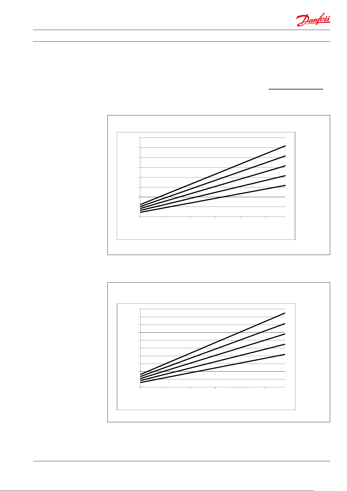
5.1 CLP 674 / CLP D 674-0025-058 typical ow curves at 80 barg (1,160 psig) pressure
The curves below show that the ow can be
changed by changing the speed of the pump.
The ow/rpm ratio is constant, and the ‘desired’
Required rpm =
80
70
60
50
40
l/min
30
20
10
0
700 1200 1700 2200 2700 3200
ow can be obtained by changing the speed to a
corresponding value. Thus, the required rpm can
be determined as:
Desired ow x Rated rpm
Rated ow
CLP/CLP D 674- 058
CLP/CLP D 674- 050
CLP/CLP D 674- 042
CLP/CLP D 674- 035
CLP/CLP D 674- 025
rpm
521B1320 / DKCFN.PD.014.M3.02 / 01.2016
CLP/CLP D 674- 058
CLP/CLP D 674- 050
CLP/CLP D 674- 042
CLP/CLP D 674- 035
CLP/CLP D 674- 025
11
Page 12

Data sheet CLP 674 / CLP D 674
5.2 CLP 674 / CLP D 674-085-152 typical ow curves at 80 barg (1,160 psig) pressure
180
160
140
120
100
l/min
80
60
40
20
0
700 1200 1700
rpm
45
40
35
CLP/ CLP D 6 74-152
CLP/ CLP D 6 74-137
CLP/ CLP D 6 74-115
CLP/ CLP D 6 74-105
CLP/CLP D 674-085
CLP/ CLP D 6 74-152
CLP/ CLP D 6 74-137
30
25
gpm
20
15
10
5
0
700 900 1100 1300 1500 1700
rpm
CLP/ CLP D 6 74-115
CLP/ CLP D 6 74-105
CLP/CLP D 674-085
12
521B1320 / DKCFN.PD.014.M3.02 / 01.2016
Page 13

Data sheet CLP 674 / CLP D 674
5.3 CLP 674 / CLP D 674-140-500 typical ow curves at 80 barg (1,160 psig) pressure
700
600
500
400
l/min
300
200
100
0
700 800 900 1000 1100 1200 1300 1400 1500
rpm
180
160
140
120
100
gpm
80
60
40
CLP/CLP D
674 -500
CLP/CLP D
674 -44 0
CLP/CLP D
674 -40 0
CLP/CLP D
674 -350
CLP/CLP D
674 -320
CLP/CLP D
674 -290
CLP/CLP D
674 -230
CLP/CLP D
674 -185
CLP/CLP D
674 -140
CLP/CLP D 674-500
CLP/CLP D 674-440
CLP/CLP D 674-400
CLP/CLP D 674-350
CLP/CLP D 674-320
CLP/CLP D 674-290
CLP/CLP D 674-230
CLP/ CLP D 6 74-185
CLP/ CLP D 6 74-140
20
0
700 800 900 1000 1100 1200 1300 1400 1500
521B1320 / DKCFN.PD.014.M3.02 / 01.2016
rpm
13
Page 14

Data sheet CLP 674 / CLP D 674
0
5
10
15
20
25
0
0,2
0,4
0,6
0,8
1
1,2
1,4
1,6
1,8
700 900 1100 1300 1500 1700 1900 2100 2300 2500 27 00 2900 3100 3300 3500
NPIP [psia]
NPIP [bara]
Speed [rpm]
NPIP CLP-025 to 058
Media: tap water @ 25°C
0
5
10
15
20
25
0
0,2
0,4
0,6
0,8
1
1,2
1,4
1,6
1,8
2
700 900 1100 1300 1500 1700
NPIP [psia]
NPIP [bara]
Speed [rpm]
NPIP CLP-085 to 152
Media: tap water @ 25°C
5.4 CLP 674/ CLP D 674-025-500 typical NPIPr curves
NPIPr depends on the speed of the CLP pump.
The curves are based on water.
14
521B1320 / DKCFN.PD.014.M3.02 / 01.2016
Page 15

Data sheet CLP 674 / CLP D 674
0
5
10
15
20
25
30
35
40
45
50
0
0,25
0,5
0,75
1
1,25
1,5
1,75
2
2,25
2,5
2,75
3
3,25
3,5
700 800 900 1000 1100 1200 1300 1400 1500
NPIP [psia]
NPIP [bara]
Speed [rpm]
NPIP CLP-140 to 500
Media: tap water @ 25°C
521B1320 / DKCFN.PD.014.M3.02 / 01.2016
15
Page 16

Data sheet CLP 674 / CLP D 674
6. Motor requirements
The required motor power can be calculated by
using the following equation:
n x V x p
P =
600.000 x η
P: Power (kW)
M: Torque (Nm)
η: Mechanical eciency
p: Pressure (barg)
n: Motor speed (rpm)
V: Displacement (cm
3
/rev.)
From the ow curves in section 5, you can
determine the rpm of the pump at the desired ow.
The required torque is calculated as follows:
V x p
M =
62.8 x η
To determine the correct motor size, both the
power and torque requirement must be veried.
Indication of the mechanical eciency of the
pump at 80 barg (1,160 psig)
CLP 674/CLP D 674-025-058 @ 3,000 rpm 0.92
CLP 674/CLP D 674-085-152 @ 1,800 rpm 0.91
CLP 674/CLP D 674-140-500 @ 1200 rpm 0.92
7. Installation The gure below illustrates how to mount the pump and connect it to electric motor/combustion
engine.
A: Pump
B: Bell housing
C: Flexible coupling
D: Motor
Min. 3 mm air
gap between
coupling parts
E: Inlet/Outlet ange
A C B D
E
16
521B1320 / DKCFN.PD.014.M3.02 / 01.2016
Page 17

Data sheet CLP 674 / CLP D 674
7.1 Filtration
As many chemicals have very low viscosity,
the CLP pumps have been designed with
very narrow clearance in order to control internal
leakage rates and improve component performance. Therefore it is important that the inlet
liquid is ltered properly to minimize the wear of
the pump.
The main lter must have a ltration eciency of
99.98% at 10 μm. We recommend that you use
precision depth lter cartridges rated 10 μm abs.
β
5000 (equivalent to a ltration eciency of
10 ≥
99.98%). Bag lters and string wound lter
cartridges typically have only 90% ltration
eciency. This means that for each 100,000
particles reaching the lter, 10,000 particles pass
through it compared to only 20 particles in a
lter with an eciency of 99.98%.
For more information on the importance of
proper ltration, please consult our publication
“Filtration” (code number 521B1009), which also
will provide you with an explanation of ltration
denitions and a guidance on how to select the
right lter.
7.2 Noise
Since the pump unit is mounted on a frame, the
overall noise level can only be determined for a
complete system. To minimize vibrations and
noise throughout the system, it is therefore very
important to mount the pump unit correctly on a
frame with dampeners and to use exible hoses
rather than metal pipes where possible.
The noise level is inuenced by:
• Pump speed:
High rpm makes more uid/structureborne pulsations/vibrations than low rpm.
• Discharge pressure:
High pressures make more noise than low
pressures.
• Pump mounting:
Rigid mounting makes more noise than
exible mounting because of the structureborne vibrations. Be sure to use dampeners
when mounting.
• Connections to pump:
Pipes connected directly to the pump make
more noise than exible hoses because of
structure-borne vibrations.
• Variable frequency drives (VFDs):
Motors regulated by VFDs can produce
more noise if the VFD does not have the
right settings.
7.3 Preferred design
Purpose of valve “V-1” and “V-2”:
Isolation valves, which make it possible to drain
the pump before servicing.
Purpose of valve “V-3”
Safety/relief valve, this valve must protect the
pump against too high inlet pressure. Too high
inlet pressure can be caused by:
• The pump is rotating in the wrong direction.
• A situation where valve V-1 is closed, valve
V-2 is open and V-5 is leaking.
Purpose of valve “V-4”:
Safety/relief valve, this valve must protect the
pump against too high outlet pressure. Too high
outlet pressure can be caused by:
• A situation where V-2 is closed.
• Check valve V-5 has been mounted in the
wrong direction.
The V-4 setting has to be 10% above the
maximum system pressure. The electric motor
must be designed for this pressure.
521B1320 / DKCFN.PD.014.M3.02 / 01.2016
17
Page 18

Data sheet CLP 674 / CLP D 674
8. Service
Purpose of “V-5”:
Check valve, this valve prevents the ow from
running reverse into the pump when connected
to a multipump system.
Purpose of “V-6”:
Bleed valve, this valve removes air from the
pump and pipes.
Purpose of “V-7” and “V-8”:
Drain valves, those valves help to empty the
pump and pipes for uid prior to service.
Danfoss CLP pumps are designed for long
periods of service-free operation to ensure
low maintenance and life cycle costs. Provided
that the pump is installed and operated
according to Danfoss specications, Danfoss CLP
pumps typically run 1 year between service.
However, the service schedule for your Danfoss
CLP pump may vary according to the application
and other factors.
The life of a pump may be greatly shortened if
Danfoss recommendations concerning system
design and operation are not followed.
Purpose of “PAL”:
Pressure alarm low, this projects the pump from
running dry.
Purpose of “TAH 1-3”:
Temperature alarm high, this protects the pump
from too high inlet media temperature.
Purpose of “TAH 1-4”:
Temperature alarm high, this protects the pump
from running hot due to over pressure or the
pump running dry.
8.1 Spare parts
The following spare parts kits are available for
the CLP pumps.
O-ring and screw set
Shaft seal set
Cylinder barrel
Valve plate set
Retainer set
Piston set
In our experience, poor filtration is the number
one cause of pump damage.
Other factors that aect pump performance and
lifetime include:
• running the pump at speeds outside
specications.
• supplying the pump with water at
temperatures higher than recommended.
• running the pump at inlet pressures
outside specications.
• running the pump at outlet pressures
outside the specications.
We recommend that you inspect your pump
after 1 year of operation even if it is running
without any noticeable problems. Replace any
worn parts if necessary, including pistons and
shaft seals, to keep your pump running eciently and to prevent breakdown. If worn parts
are not replaced, then our guidelines recommend more frequent inspection.
If your pump is running continuously under
“high end performance” conditions we recommend that you inspect your pump after half a
year of operation, replacing worn parts if
necessary.
8.2 Spare part suitcase
Danfoss High Pressure Pumps can provide a
spare part suitcase containing all necessary parts
and instructions for overhaul of CLP pumps.
The suitcase can at any time be returned for rell
of consumed parts.
Contact Danfoss High Pressure Pumps for price
and availability of the spare part suitcase.
18
521B1320 / DKCFN.PD.014.M3.02 / 01.2016
Page 19

Data sheet CLP 674 / CLP D 674
9. Dimensions and
connections
9.1 CLP 674 / CLP D 674-025-058 pump
521B1320 / DKCFN.PD.014.M3.02 / 01.2016
19
Page 20

Data sheet CLP 674 / CLP D 674
9.2 CLP 674 / CLP D 674-085-152 pump
20
521B1320 / DKCFN.PD.014.M3.02 / 01.2016
Page 21

Data sheet CLP 674 / CLP D 674
9.3 CLP 674 / CLP D 674-140-500 pump
521B1320 / DKCFN.PD.014.M3.02 / 01.2016
21
Page 22

Data sheet CLP 674 / CLP D 674
10. Pump and bell-housing
Pump and bell-housing
“ L”
Pump type Motor size ICE size
CLP 674 / CLP D 674-025-058
CLP 674 / CLP D 674-025-058
CLP 674 / CLP D 674-025-058
CLP 674 / CLP D 674-025-058
CLP 674 / CLP D 674-025-058
CLP 674 / CLP D 674 -085-152 7,5 kW 132 M 437 17. 2
CLP 674 / CLP D 674 -085-152 15 k W 160L 473 18.6
CLP 674 / CLP D 674-085-152 30 kW 200L 473 18.6
CLP 674 / CLP D 674 -085-152 55 kW 250M 517 20.4
CLP 674 / CLP D 674 -140-500 30 kW 200L 592 23.3
CLP 674 / CLP D 674-140-500 55 kW 250M 629 24.8
CLP 674 / CLP D 674-140-500 132 kW 315L 674 26.5
CLP 674 / CLP D 674-140-500 200 kW 315L 674 26.5
3 kW 100L 302 11,9
4 kW 112M 302 11, 9
5,5 kW 132S 327 12,9
7,5 kW 132S 327 12,9
11 kW 160M 371 14,6
Length 'L'
[mm]
Length 'L'
[in]
22
521B1320 / DKCFN.PD.014.M3.02 / 01.2016
Page 23

Data sheet CLP 674 / CLP D 674
11. Pump base plate
solution
Pump base plate solution
Danfoss High Pressure Pumps can provide a
standard baseplate for all standard motor
pump units. Custom made baseplates are
available on request.
Contact Danfoss High Pressure Pumps for
price and leadtime.
521B1320 / DKCFN.PD.014.M3.02 / 01.2016
23
Page 24

Danf
already on order pro
All trademarks in this material are property of the respec
Danfoss A/S
High Pressure Pumps
Nordborgvej 81
DK-6430 Nordborg
Denmark
oss can accept no responsibility for possible errors in catalogues, brochures and other printed material. Danfoss reserves the right to alter its products without notice. This also applies to products
vided that such alterations can be made without subsequential changes being necessary eady agreed.
© Danfoss | DCS (im) | 2016.01
tive companies. Danfoss and the Danfoss logotype are trademarks of Danfoss A/S. All rights reserved.
521B1320 | DKCFN.PD.014.M3.02 | 24
 Loading...