

Page 1
Installation Guide
Circulation set for TDP-F units
Zirkulationsset für TDP-F Stationen
Div.788 Code No. 004U8400
Div.789 Code No. 004U8401
English - GB
If the household plumbing system includes hot water recirculation the substation must be connected to the hot water recirculation system
by using this circulation set.
It is to be recommended to prepare the substation for recirculation BEFORE mounting it on the wall.
The recirculation pipe in your household plumbing system must be connected to a nipple, mounted on the circulation pipe of the substation. - See the following pages for information about preparation of substation for and connection to the DHW recirculation system.
Remember always to mount circulation pump, non-return valve on the circulation pipe and to mount safety valve on the DCW inlet.
The pump must be installed so that the pump is pumping water towards the substation.
If a time-controlled pump is used, it is to be recommended that the circulation water temperature is set to approx. 35 °C.
If the circulation pump (outside the substation) is switched o for a longer period, it is to be recommended that the Danfoss bypass thermostat is closed during the same period.
Div.484 Code No. 004U8403
Div.487 Code No. 004U8405
NOTE!
Please note that substations with Danfoss AVE expanion unit must not be used on systems with DHW recirculation.
German - DE
Siehe bitte Seiten 13 bis 24.
Danfoss District Energy VI.IE.A1.5B DKDHR
1
Page 2
Installation Guide TDP-F units
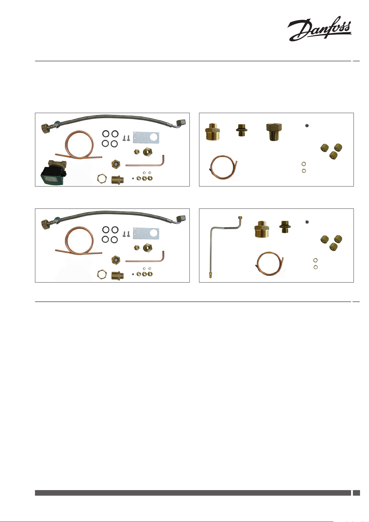
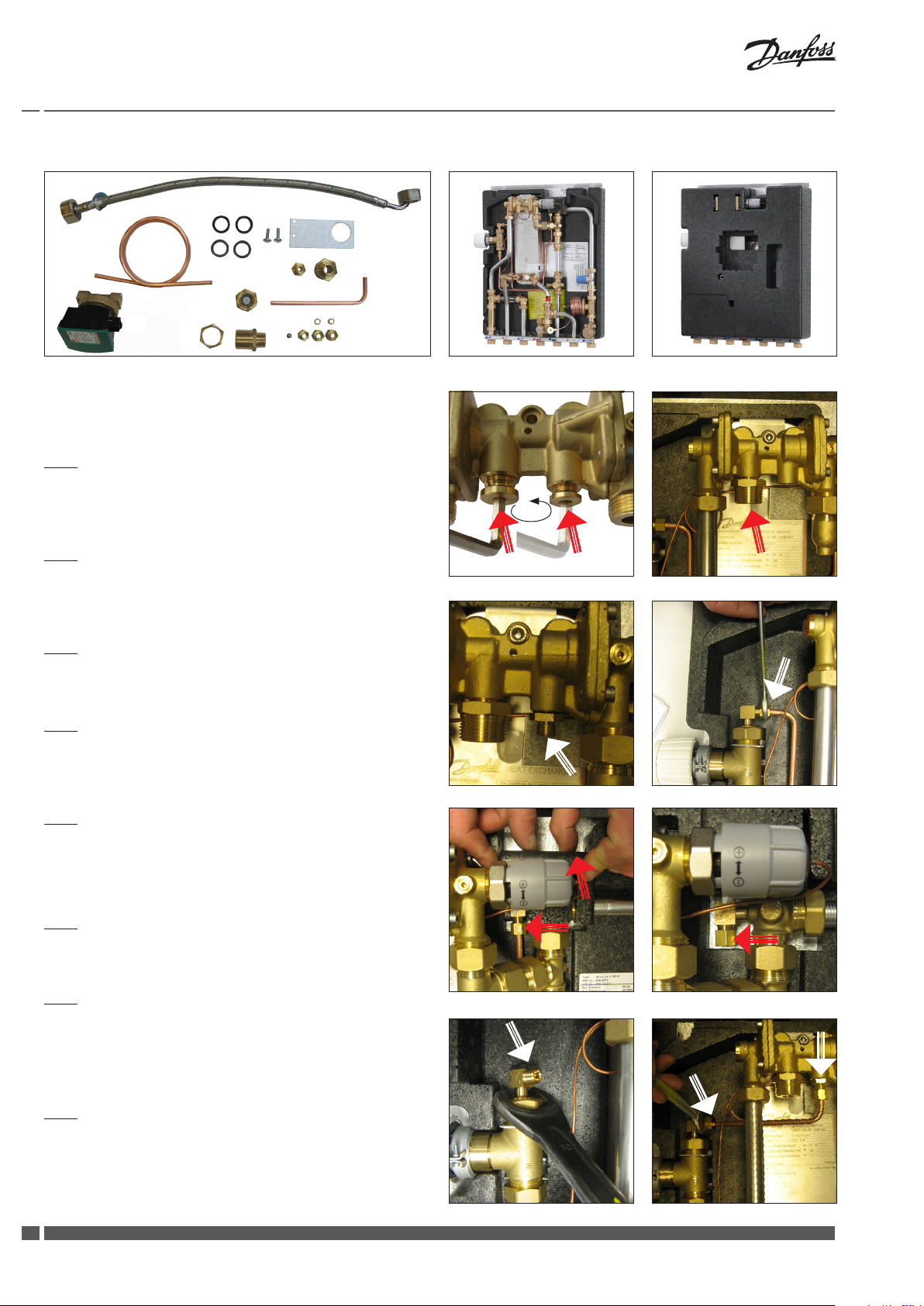
Installation instructions - recirculation connection - Circulation set 1 - 004U8400
G2
I
G1
H
E2
B
J
K
M
C
L
You must always t a pump and non-return valve to the recirculation pipe, with ow direction towards the substation.
A safety valve must be mounted in the DCW inlet.
Fig. 1
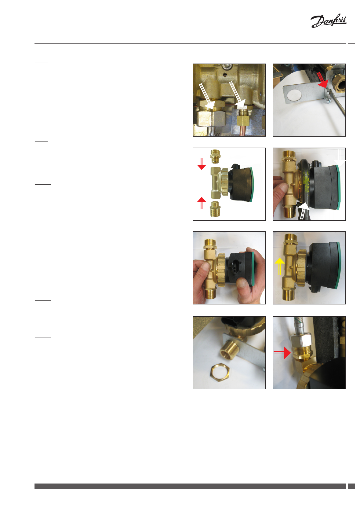
Remove the nipples/plugs from the domestic hot water controller
(use a 6 mm Allen key).
Fig. 2
Mount hexagon nipple A in the DHW controller (seal with approved
sealing material, - i.e. hemp, tape, glue).
Fig. 3
Fit pipe bushing B in the DHW controller.
A
E1
F
D
Akva Lux II TDP-F, Type 004U8264
Fig. 1 Fig. 2
Fig. 4
Loosen union nut and demount the existing capillary tube from
the bypass thermostat.
Fig. 5
Lift up the movable section of the insulation cover, as shown, loosen
union nut and demount the existing capillary tube from the angle
piece. Do not re-use the capillary tube.
Fig. 6
Plug the hole with ball C and union nut D.
Fig. 7
Loosen union nut on T-piece for Danfoss bypass thermostat and
turn the angle piece for the capillary tube connection to a 45 degree angle and fasten union nut again.
Fig. 8
Fit new capillary tube E1 by means of cutting rings F and union nuts
D between the bypass thermostat and the pipe bushing B. Tighten
with single end wrench.
Fig. 3 Fig. 4
Fig. 5 Fig. 6
Fig. 7 Fig. 8
2
DKDHR VI.IE.A1.5B Danfoss District Energy
Page 3
Installation Guide TDP-F units
Fig. 9
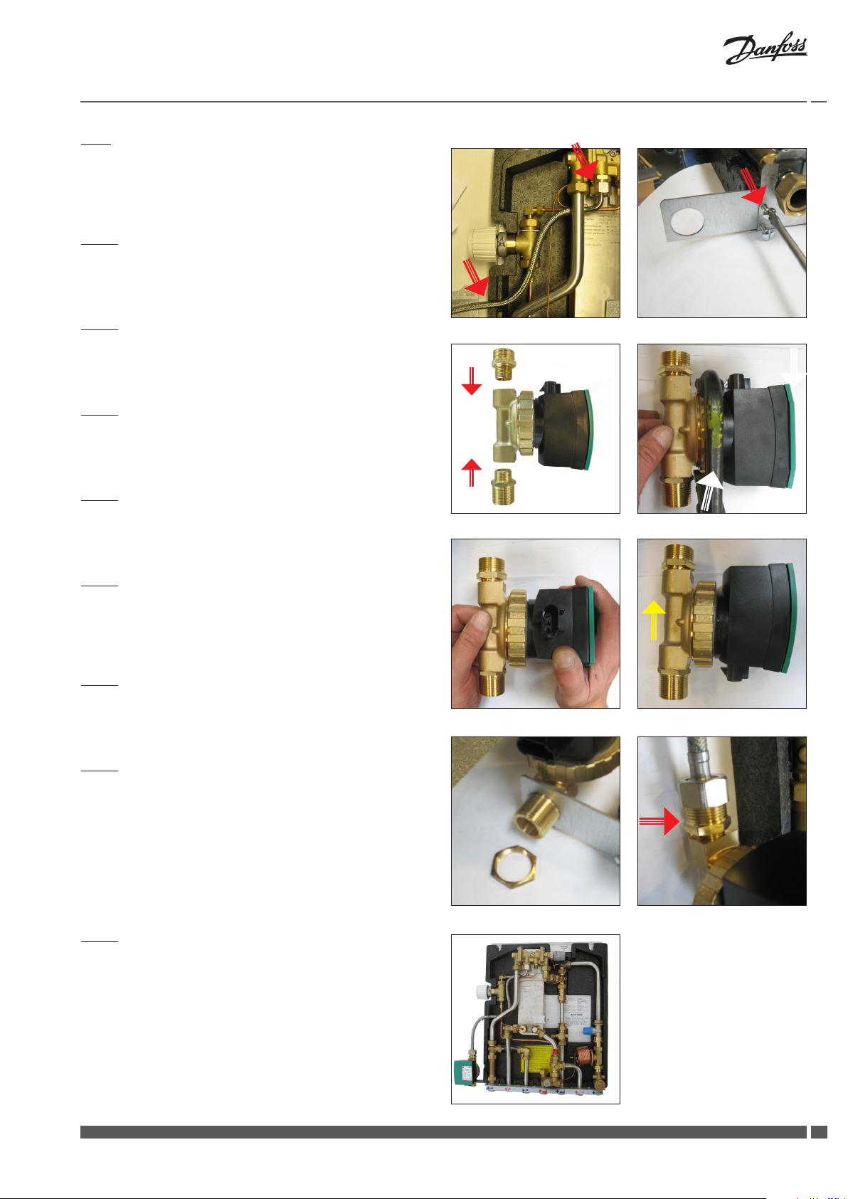
Fit circulation hose end G1 in hexagon nipple A (do not forget gasket!), and t the hose through the cut-out in the left side of the rear
insulation cover.
Fig. 10
Mount bracket H for recirculation connection on the mounting rail,
as shown, and fasten by means of two screws I.
Fig. 11
Mount non-return valve J and hexagon nipple K in the pump, as
shown on the photo to your right.
Fig. 12
Loosen union nut.
Fig. 13
Turn pump motor head by 180 degrees. Tighten the union nut
again.
Fig. 14
Please note that the arrow on the back of the housing indicates
the dirction of ow. - Please note the position of the arrow as
shown in the photo to your right.
Fig. 15
Fit pump in bracket H and fasten with locknut L.
Fig. 9 Fig. 10
J
K
Fig. 11
Fig. 13 Fig.14
Fig.12
Fig. 16
Fit circulation hose end G2 in non-return valve J. (Do not forget
gasket!)
Fig. 15 Fig.16
Fig. 17
Akva Lux II TDP-F, prepared for domestic hot water recirculation.
Fig.17
Danfoss District Energy VI.IE.A1.5B DKDHR
33
Page 4
Installation Guide TDP-F units
G2
I
G1
H
E2
B
J
K
M
C
L
You must always t a pump and non-return valve to the recirculation pipe, with ow direction towards the substation.
A safety valve must be mounted in the DCW inlet.
Fig. 1
Remove the nipples/plugs from the domestic hot water controller
(use a 6 mm Allen key).
A
E1
F
D
Akva Lux II TDP-F, Type 004U8089
Akva Lux II TDP-F, Type 004U8044
Cover for wall mounting
Cover for recess mounting
Fig. 2
Mount hexagon nipple A in the DHW controller (seal with approved
sealing material, - i.e. hemp, tape, glue).
Fig. 3
Fit pipe bushing B in the DHW controller.
Fig. 4
Remove the existing capillary tube and union nut from bypass
thermostat and angle piece (do not re-use).
Fig. 5
Plug the hole in the angle piece with the steel ball C and a union
nut D.
Fig. 6
Fit new capillary tube E2 in bypass thermostat by means of cutting
rings F and a union nut D. Tighten with single end wrench.
Fig. 1 Fig. 2
Fig. 3 Fig. 4
Fig. 5 Fig. 6
4
DKDHR VI.IE.A1.5B Danfoss District Energy
Page 5
Installation Guide TDP-F units
Fig. 7
Fit/screw hose end G1 onto the hexagon nipple A and t the other
end of the capillary tube E2 in pipe bushing B by means of a cutting
ring F and a union nut D. Tighten with single end wrench.
Fig. 8
Mount bracket H for recirculation connection on the mounting rail,
as shown, and fasten by means of two screws I.
Fig. 9
Mount non-return valve J and hexagon nipple K in the pump, as
shown in the photo to your right.
Fig. 10
Loosen union nut.
Fig. 11
Turn pump motor head by 180 degrees. Tighten the union nut
again.
Fig. 12
Please note that the arrow on the back of the housing indicates
the dirction of ow. - Please note the position of the arrow as
shown in the photo to your right.
Fig. 13
Fit pump in bracket H and fasten with locknut L.
Fig. 7 Fig. 8
J
K
Fig. 9
Fig. 11 Fig.12
Fig.10
Fig. 14
Fit circulation hose end G2 in non-return valve J. (Do not forget
gasket!)
Fig. 13 Fig.14
Danfoss District Energy VI.IE.A1.5B DKDHR
55
Page 6
Installation Guide TDP-F units
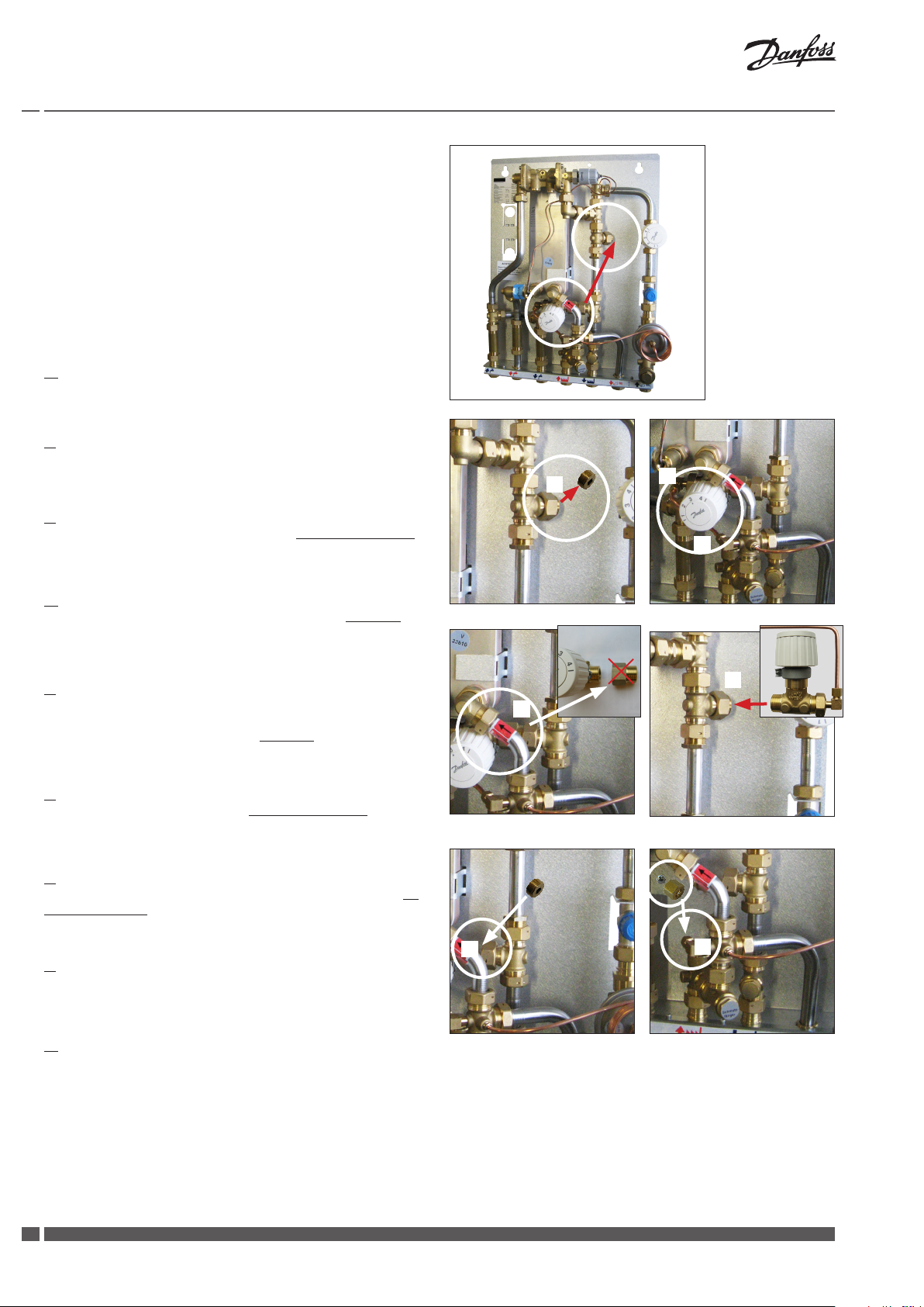
PLEASE NOTE (only for 004U8044):
For systems with DHW recirculation the bypass thermostat
must alway be installed before the heat meter.
On substations, that are supplied with bypass thermostat mounted after the heat meter (Akva Lux II TDP-F, Type
004U8044), the bypass thermostat must therefore be relocated
before the substation is prepared for recirculation, - i.e. the bypass thermostat must be mounted before the heat meter.
Please follow the below instructions:
1.
Start by shutting o all connections to the substation.
2.
First follow the instructions for Fig. 1, 2 and 3 on page 16.
3.
Then demount 3/4” plug in T-piece (pos. A), as illustrated in g. 1.
A
C
D
4.
Remove the existing capillary tube from pos. C to D. See g. 2.
5.
Demount bypass thermostat incl. 3/4” reducer bushing from pos. B.
Unscrew 3/4” reducer bushing from bypass thermostat (the 3/4”
reducer bushing is not to be reused). See g. 3.
6.
Mount bypass thermostat in pos A, as illustrated in g. 4.
7.
Plug the hole in pos. B with 3/4” plug (from pos A) and gasket, as
illustrated in g. 5.
8.
Plug the hole in pos. D with a steel ball and 6 mm union nut.
9.
Finally follow instructions for g. 6 to 14 on pages 16 and 17.
Fig. 1
B
Fig. 3 Fig. 4
B
Fig. 5
Fig. 2
Fig. 6
A
D
6
DKDHR VI.IE.A1.5B Danfoss District Energy
Page 7
Installation Guide TDP-F units
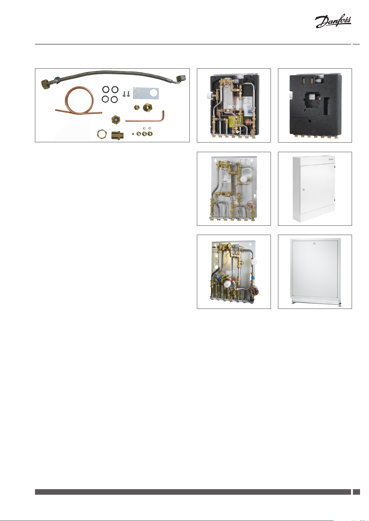
Installation instructions - recirculation connection - Circulation set 2 - 004U8401
G2
I
G1
H
E2
B
J
K
C
L
You must always t a pump and non-return valve to the recirculation pipe, with ow direction towards the substation.
A safety valve must be mounted in the DCW inlet.
For recirculation connection please refer to installation instructions
for circulation set 1 - 004U8400.
A
E1
F
D
Akva Lux II TDP-F, Type 004U8264
Akva Lux II TDP-F, Type 004U8089
Cover for wall mounting
Akva Lux II TDP-F, Type 004U8044
Cover for recess mounting
Danfoss District Energy VI.IE.A1.5B DKDHR
77
Page 8
Installation Guide TDP-F units
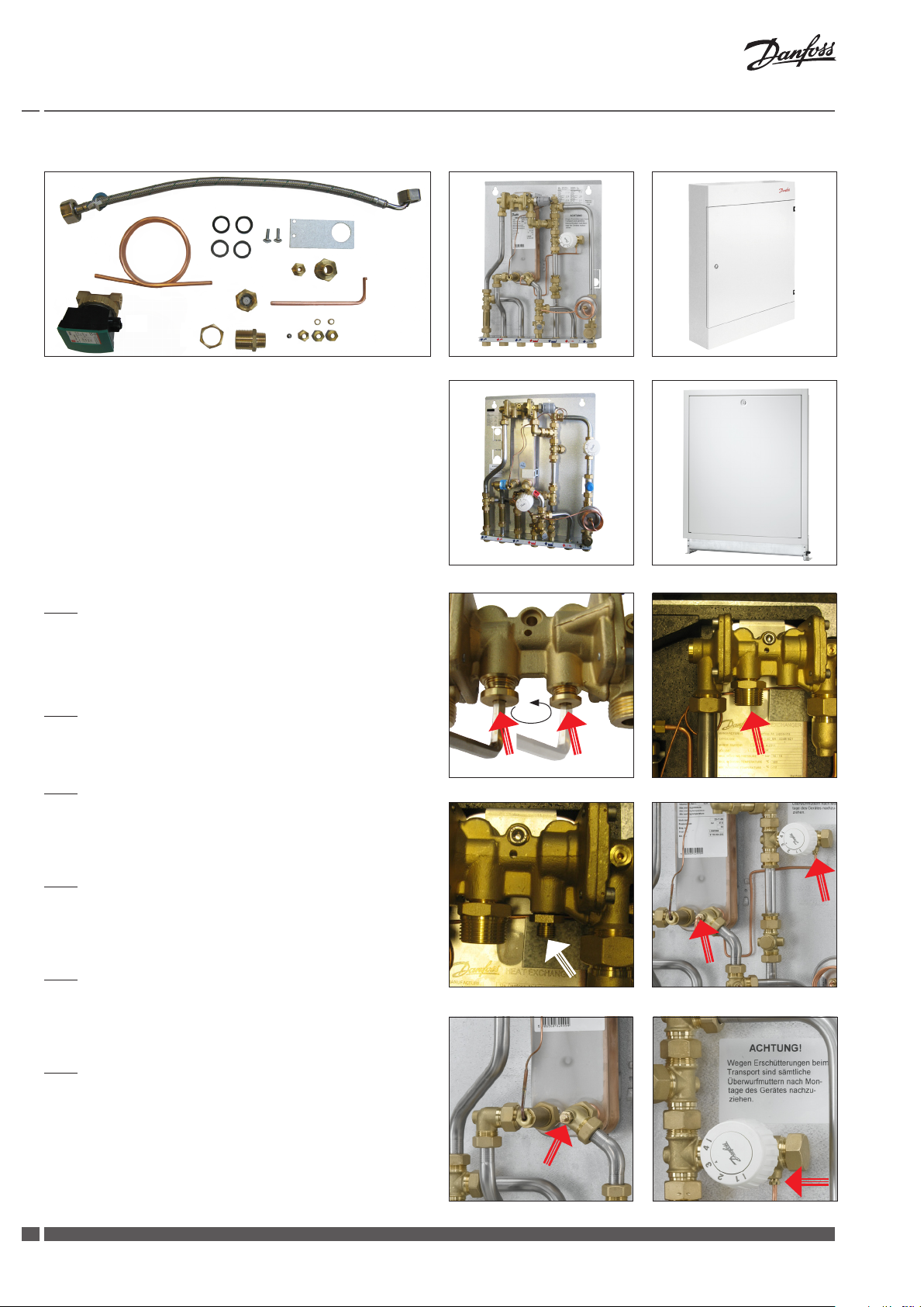
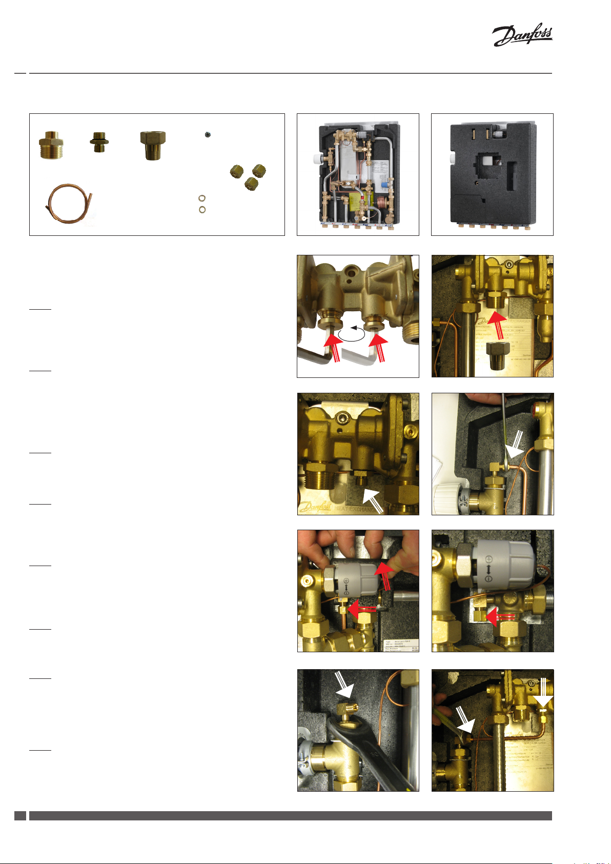
Installation instructions - recirculation connection - Circulation set 3 - 004U8403
A B
D
C
G
You must always t a pump and non-return valve to the recirculation pipe, with ow direction towards the substation.
A safety valve must be mounted in the DCW inlet.
Fig. 1
Remove the nipples/plugs from the domestic hot water controller
(use a 6 mm Allen key).
Fig. 2
Mount hexagon nipple A in the DHW controller (seal with approved
sealing material, - i.e. hemp, tape, glue), and mount hexagon nipple
C and union nut D in hexagon nipple A (for tting of recirculation
pipe.
E
F
H
Akva Lux II TDP-F, Type 004U8264
Fig. 1 Fig. 2
Fig. 3
Fit pipe bushing B in the DHW controller.
Fig. 4
Loosen union nut and demount the existing capillary tube from
the bypass thermostat.
Fig. 5
Lift up the movable section of the insulation cover, as shown, loosen
union nut and demount the existing capillary tube from the angle
piece. Do not re-use the capillary tube.
Fig. 6
Plug the hole with ball E and union nut F.
Fig. 7
Loosen union nut on T-piece for Danfoss bypass thermostat and
turn the angle piece for the capillary tube connection to a 45 degree angle and fasten union nut again.
Fig. 8
Fit new capillary tube G by means of cutting rings H and union nuts
F between the bypass thermostat and the pipe bushing B. Tighten
with single end wrench.
Fig. 3
Fig. 5 Fig. 6
Fig. 4
Fig. 7 Fig. 8
8
DKDHR VI.IE.A1.5B Danfoss District Energy
Page 9
Installation Guide TDP-F units
A B
D
C
G
You must always t a pump and non-return valve to the recirculation pipe, with ow direction towards the substation.
A safety valve must be mounted in the DCW inlet.
Fig. 1
Remove the nipples/plugs from the domestic hot water controller
(use a 6 mm Allen key).
E
F
H
Akva Lux II TDP-F, Type 004U8089
Akva Lux II TDP-F, Type 004U8044
Cover for wall mounting
Cover for recess mounting
Fig. 2
Mount hexagon nipple A in the DHW controller seal with approved
sealing material, - i.e. hemp, tape, glue), and mount hexagon nipple
C and union nut D in hexagon nipple A (for tting of recirculation
pipe.
Fig. 3
Fit pipe bushing B in the DHW controller.
Fig. 4
Remove the existing capillary tube and union nut from bypass
thermostat and angle piece (do not re-use).
Fig. 5
Plug the hole in the angle piece with steel ball E and union nut F.
Fig. 6
Fit new capillary tube G in bypass thermostat by means of a cutting
ring H and a union nut F. Tighten with single end wrench.
Fig. 1 Fig. 2
Fig. 3 Fig. 4
Fig. 5 Fig. 6
Danfoss District Energy VI.IE.A1.5B DKDHR
99
Page 10

Installation Guide TDP-F units
Fig. 7
Fit the other capillary tube end G in pipe bushing B by means of a
cutting ring H and a union nut F. Tighten with single end wrench.
PLEASE NOTE (only for 004U8044):
For systems with DHW recirculation the bypass thermostat
must alway be installed before the heat meter.
On substations, that are supplied with bypass thermostat mounted after the heat meter (Akva Lux II TDP-F, Type
004U8044), the bypass thermostat must therefore be relocated
before the substation is prepared for recirculation, - i.e. the bypass thermostat must be mounted before the heat meter.
Fig. 7
Please follow the below instructions:
1.
Start by shutting o all connections to the substation.
2.
First follow the instructions for Fig. 1, 2 and 3 on page 21.
3.
Then demount 3/4” plug in T-piece (pos. A), as illustrated in g. 1.
4.
Remove the existing capillary tube from pos. C to D. See g. 2.
5.
Demount bypass thermostat incl. 3/4” reducer bushing from pos. B.
Unscrew 3/4” reducer bushing from bypass thermostat (the 3/4”
reducer bushing is not to be reused). See g. 3.
6.
Mount bypass thermostat in pos A, as illustrated in g. 4.
7.
Plug the hole in pos. B with 3/4” plug (from pos A) and gasket, as
illustrated in g. 5.
A
Fig. 1 Fig. 2
B
Fig. 3 Fig. 4
C
D
A
8.
Plug the hole in pos. D with a steel ball and 6 mm union nut.
B
9.
Finally follow above instructions for g. 6 and 7 on pages 21 and
22.
Fig. 5
10
DKDHR VI.IE.A1.5B Danfoss District Energy
Fig. 6
D
Page 11

Installation Guide TDP-F units
Installation instructions - recirculation connection - Circulation set 4 - 004U8405
C
D
YYou must always t a pump and non-return valve to the recirculation pipe, with ow direction towards the substation.
A safety valve must be mounted in the DCW inlet.
PLEASE NOTE!
This circulation set can be mounted only on substations without
insulation.
Fig. 1
Remove the nipples/plugs from the domestic hot water controller
(use a 6 mm Allen key).
A B
G
E
F
H
Akva Lux II TDP-F, Type 004U8089
Akva Lux II TDP-F, Type 004U8044
Cover for wall mounting
Cover for recess mounting
Fig. 2
Mount hexagon nipple A in the DHW controller (seal with approved
sealing material, - i.e. hemp, tape, glue).
Fig. 3
Mount circulation pipe C, incl. hexagon nipple D, in hexagon nipple
A.
Fig. 4
Fit pipe bushing B in the DHW controller.
Fig. 5
Remove the existing capillary tube and union nut from bypass
thermostat and angle piece (do not re-use).
Fig. 6
Plug the hole in the angle piece with steel ball E and union nut F.
Fig. 1 Fig. 2
Fig. 3 Fig. 4
Fig. 5 Fig. 6
Danfoss District Energy VI.IE.A1.5B DKDHR
1111
Page 12

Installation Guide TDP-F units
Fig. 7
Fit the new capillary tube G in the bypass thermostat by means of
a cutting ring H and a union nut F. Tighten with single end wrench.
Fig. 8
Fit the other capillary tube end in the pipe bushing by means of a
cutting ring H and a union nut F. Tighten with single end wrench.
PLEASE NOTE (only for 004U8044):
For systems with DHW recirculation the bypass thermostat
must alway be installed before the heat meter.
On substations, that are supplied with bypass thermostat mounted after the heat meter (Akva Lux II TDP-F, Type
004U8044), the bypass thermostat must therefore be relocated
before the substation is prepared for recirculation, - i.e. the bypass thermostat must be mounted before the heat meter.
Fig. 7 Fig. 8
Please follow the below instructions:
1.
Start by shutting o all connections to the substation.
2.
First follow the instructions for Fig. 1, 2, 3 and 4 on page 23.
3.
Then demount 3/4” plug in T-piece (pos. A), as illustrated in g. 1.
4.
Remove the existing capillary tube from pos. C to D. See g. 2.
5.
Demount bypass thermostat incl. 3/4” reducer bushing from pos. B.
Unscrew 3/4” reducer bushing from bypass thermostat (the 3/4”
reducer bushing is not to be reused). See g. 3.
6.
Mount bypass thermostat in pos A, as illustrated in g. 4.
7.
Plug the hole in pos. B with 3/4” plug (from pos A) and gasket, as
illustrated in g. 5.
A
Fig. 1 Fig. 2
B
Fig. 3 Fig. 4
C
D
A
8.
Plug the hole in pos. D with a steel ball and 6 mm union nut.
B
9.
Finally follow above instructions for g. 7 and 8 on this page.
Fig. 5
12
DKDHR VI.IE.A1.5B Danfoss District Energy
Fig. 6
D
Page 13

Installation Guide TDP-F units
Zirkulationsset für TDP-F Stationen
Div.788 Code No. 004U8400
Div.789 Code No. 004U8401
German - DE
Wenn eine Zirkulationsleitung in der Hausinstallation vorhanden ist, ist die Station an die Zirkulationsleitung anzuschließen, und eine
Umrüstung von Bypassbetrieb auf TWW-Zirkulation ist mittels dieses Zirkulationssatzes vorzunehmen.
Es wird empfohlen die Station für TWW-Zirkulation VOR der Montage auf der Wand vorzubereiten.
Die Zirkulationsleitung der Hausinstallation ist an einen Messing-Nippel, den auf dem Zirkulationsschlauch der Station montieret ist, anzuschliessen. - Siehe die folgende Seiten für weitere Informationen über Zirkulationsanschluss.
Bitte einbau von Umwälzpumpe und Rückschlagventil in der Zirkulationsleitung beachten und Sicherheitsventil in der Kaltwasserzuleitung einzubauen. Die Fleißrichtung der Pumpe ist in Richtung Station.
Wird die Umwälzpumpe über eine Schaltuhr gesteuert, empfehlen wir, dass die Zirkulationswassertemperatur auf ungefähr. 35 °C eingestellt wird.
Wenn die Umwälzpumpe (außerhalb der Station) für einen längeren Zeitraum abgeschaltet wird, wird es empfohlen, dass der Danfoss
Bypass Thermostat im gleichen Zeitraum geschlossen wird.
Div.484 Code No. 004U8403
Div.487 Code No. 004U8405
BITTE BEMERKEN!
Der AVE Druckausgleichventil ist nicht auf Systemen mit TWW-Zirkulation zu verwenden.
Danfoss District Energy VI.IE.A1.5B DKDHR
1313
Page 14

Installation Guide TDP-F units
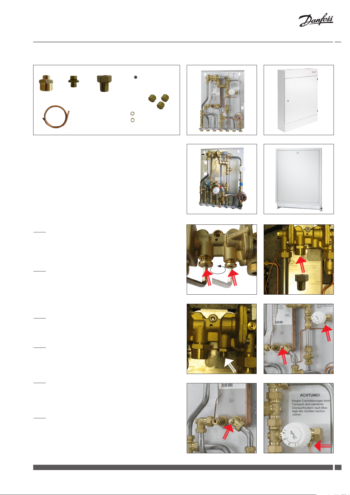
Zirkulationsanschluss - Zirkulationsset 1 - 004U8400
G2
I
G1
H
E2
B
J
K
M
C
L
Bitte Einbau von Umwälzpumpe und Rückschlagventil in der Zirkulationsleitung beachten. Die Fließrichtung der Pumpe ist in Richtung
Station.
Sicherheitsventil in der Kaltwasserzuleitung einbauen.
Abb. 1
Die Nippel/Pfropfe vom Regler abbauen (mit 6 mm Inbusschlüssel).
Abb. 2
Messingnippel A in den Regler einbauen (mit zugelassenem Dichtmaterial dichten, - z.B Hanf, Dichtband, Klebsto).
Abb. 3
Nippel B in den Regler einbauen.
A
E1
F
D
Akva Lux II TDP-F, Typ 004U8264
Abb. 1 Abb. 2
Abb. 4
Überwurfmutter lösen und Kapillarrohr von Bypass Thermostat
abbauen.
Abb. 5
Isolierabdeckung heben, Überwurfmutter lösen und Kapillarrohr
vom Winkelstück abbauen (Kapillarrohr verschrotten).
Abb. 6
Mit Kugel C und Überwurfmutter D abdecken.
Abb. 7
Überwurfmutter in T-Stück für Danfoss Bypass Thermostat lösen
und Winkel für Kapillarrohranschluss um ungefähr 45 Grad drehen
und Überwurfmutter wieder festspannen.
Abb. 8
Neues Kapillarrohr E1 mittels Schneidring F und Überwurfmutter D
zwischen Bypass Thermostat und Messingnippel B einbauen. Mit
Schraubenschlüssel festspannen.
Abb. 3 Abb. 4
Abb. 5 Abb. 6
Abb. 7 Abb. 8
14
DKDHR VI.IE.A1.5B Danfoss District Energy
Page 15

Installation Guide TDP-F units
Abb. 9
Zirkulationsschlauchende G1 in Messingnippel A einbauen (Dichtung nicht vergessen!), und den Zirkulationsschlauch durch den
Ausschnitt in der linken Seite im Rückisolierung führen.
Abb. 10
Beschlag H für Zirkulationsanschluss auf die Montageplatte, wie
gezeigt, anbringen und mittels die zwei Schrauben I festschrauben.
Abb. 11
Rückschlagventil J und Messingnippel K in die Pumpe wie gezeigt
einbauen.
Abb. 12
Überwurfmutter lösen.
Abb. 13
Pumpenmotorkopf um 180 Grad drehen. Überwurfmutter wieder
anziehen.
Abb. 14
Beachten Sie bitte, dass der Pfeil auf der Rückseite des Gehäuses
die Fließrichtung angibt. - Bitte gezeigte Pfeilrichtung beachten.
Abb. 15
Pumpe in Beschlag H einbauen und mit Sicherungsmutter L
befestigen.
Abb. 9 Abb. 10
J
K
Abb. 11
Abb. 13 Abb.14
Abb.12
Abb. 16
Zirkulationsschlauchende G2 in Rückschlagventil J einbauen.
(Dichtung nicht vergessen!)
Abb. 15 Abb.16
Abb. 17
Akva Lux II TDP-F, vorbereitet für Zirkulationsanschluss.
Abb.17
Danfoss District Energy VI.IE.A1.5B DKDHR
1515
Page 16

Installation Guide TDP-F units
G2
I
G1
H
E2
B
J
K
M
C
L
Bitte Einbau von Umwälzpumpe und Rückschlagventil in der Zirkulationsleitung beachten. Die Fließrichtung der Pumpe ist in Richtung
Station.
Sicherheitsventil in der Kaltwasserzuleitung einbauen.
Abb. 1
Die Nippel/Pfropfe vom Regler abbauen (mit 6 mm Inbusschlüssel).
A
E1
F
D
Akva Lux II TDP-F, Typ 004U8089
Akva Lux II TDP-F, Typ 004U8044
Verkleidung für Aufputzmontage
Verkleidung für Unterputzmontage
Abb. 2
Messingnippel A in den Regler einbauen (mit zugelassenem Dichtmaterial dichten, - z.B Hanf, Dichtband, Klebsto).
Abb. 3
Nippel B in den Regler einbauen.
Abb. 4
Kapillarrohr und Überwurfmutter von Bypass Thermostat und
Winkelstück abbauen (verschrotten).
Abb. 5
Mittels Kugel C und Überwurfmutter D in Winkelstück zupfropfen.
Abb. 6
Neues Kapillarrohr E2 in Bypass Thermostat mittels Schneidring
F und Überwurfmutter D in Bypass Thermostat einbauen. - Mit
Schraubenschlüssel festspannen.
Abb. 1 Abb. 2
Abb. 3 Abb. 4
Abb. 5 Abb. 6
16
DKDHR VI.IE.A1.5B Danfoss District Energy
Page 17

Installation Guide TDP-F units
Abb. 7
Schlauchende G1 an Messingnippel A festschrauben. Das andere
Kapillarrohrende E2 in Messingnippel B mittels Schneidring F und
Überwurfmutter D einbauen. - Mit Schraubenschlüssel festspannen.
Abb. 8
Beschlag H für Zirkulationsanschluss auf die Montageplatte, wie
gezeigt, anbringen und mittels die zwei Schrauben I festschrauben.
Abb. 9
Rückschlagventil J und Messingnippel K in die Pumpe wie gezeigt
einbauen.
Abb. 10
Überwurfmutter lösen.
Abb. 11
Pumpenmotorkopf um 180 Grad drehen. Überwurfmutter wieder
anziehen.
Abb. 12
Beachten Sie bitte, dass der Pfeil auf der Rückseite des Gehäuses
die Fließrichtung angibt. - Bitte gezeigte Pfeilrichtung beachten,
wie in Abb. 12 angegeben.
Abb. 13
Pumpe in Beschlag H einbauen und mit Sicherungsmutter L
befestigen.
Abb. 7 Abb. 8
J
K
Abb. 9
Abb. 11 Abb.12
Abb.10
Abb. 14
Zirkulationsschlauchende G2 in Rückschlagventil J einbauen.
(Dichtung nicht vergessen!)
Abb. 13 Abb.14
Danfoss District Energy VI.IE.A1.5B DKDHR
1717
Page 18

Installation Guide TDP-F units
Beachten Sie bitte (gilt nur für Typ 004U8044):
Auf Anlagen mit Zirkulation ist der Bypass Thermostat immer
vor dem Wärmengenzähler einzubauen.
Auf Stationen, die mit Thermostat nach dem Wärmenmengenzähler (Akva Lux II TDP-F, Typ 004U8044) geliefert werden, ist
der Bypass Thermostat deshalb vor Umrüstung af TWW-Zirkulation zu verlegen, - d.h. vor dem Wärmemengenzähler einzubauen.
Befolgen Sie bitte die untenstehenden Instruktionen:
1.
Zuerst alle Verbindungen/Anschlüsse zu der Wohnungsstation
abschalten/absperren.
2.
Danach die Instruktionen für Abb. 1, 2 und 3 auf Seite 16 folgen.
3.
Dann 3/4” Pfropfen in T-Stück (Pos. A) abbauen, wie in Abb. 1
abgebildet.
A
C
D
4.
Kapillarrohr von Pos. C zu D abbauen (verschrotten). Siehe Abb. 2.
5.
Bypass-Thermostat einschl. 3/4” Reduzierbusche (Pos. B) abbauen.
Die 3/4” Reduzierbusche von Bypass-Thermostat abbauen (die 3/4”
Reduzierbusche ist nicht wieder zu verwenden). Siehe Abb. 3.
6.
Bypass-Thermostat in Pos A einbauen, wie in Abb. 4 abgebildet.
7.
Das Loch in Pos. B mittels dem 3/4” Pfropfen (von Pos. A) + Dichtung zupfropfen, wie in Abb. 5 abgebildet.
8.
Das Loch in Pos. D mittels Kugel und 6 mm Überwurfmutter zupfropfen.
9.
Schließlich den Anweisungen für Abb. 6 bis 14 auf den Seiten 16
und 17 folgen.
Abb. 1
B
Abb. 3 Abb. 4
B
Abb. 5
Abb. 2
Abb. 6
A
D
18
DKDHR VI.IE.A1.5B Danfoss District Energy
Page 19

Installation Guide TDP-F units
Zirkulationsanschluss - Zirkulationsset 2 - 004U8401
G2
I
G1
H
E2
B
J
K
C
L
Bitte Einbau von Umwälzpumpe und Rückschlagventil in der Zirkulationsleitung beachten. Die Fließrichtung der Pumpe ist in Richtung
Station.
Sicherheitsventil in der Kaltwasserzuleitung einbauen.
Für Zirkulationsanschluss siehe bitte Anleitung für Zirkulationsset
1 - 004U8400.
A
E1
F
D
Akva Lux II TDP-F, Typ 004U8264
Akva Lux II TDP-F, Typ 004U8089
Verkleidung für Aufputzmontage
Akva Lux II TDP-F, Typ 004U8044
Verkleidung für Unterputzmontage
Danfoss District Energy VI.IE.A1.5B DKDHR
1919
Page 20

Installation Guide TDP-F units
Zirkulationsanschluss - Zirkulationsset 3 - 004U8403
A B
D
C
G
Bitte Einbau von Umwälzpumpe und Rückschlagventil in der Zirkulationsleitung beachten. Die Fließrichtung der Pumpe ist in Richtung
Station.
Sicherheitsventil in der Kaltwasserzuleitung einbauen.
Abb. 1
Die Nippel/Pfropfe vom Regler abbauen (mit 6 mm Inbusschlüssel).
Abb. 2
Messingnippel A in den Regler einbauen (mit zugelassenem Dichtmaterial dichten, - z.B Hanf, Dichtband, Klebsto) und Messingnippel C und Überwurfmutter D in Messingnippel A einbauen. (Für
Einbau eines Zirkulationsrohres).
E
F
H
Akva Lux II TDP-F, Typ 004U8264
Abb. 1 Abb. 2
Abb. 3
Nippel B in den Regler einbauen.
Abb. 4
Überwurfmutter lösen und Kapillarrohr von Bypass Thermostat
abbauen.
Abb. 5
Isolierabdeckung heben, Überwurfmutter lösen und Kapillarrohr
vom Winkelstück abbauen (Kapillarrohr verschrotten).
Abb. 6
Mit Kugel E und Überwurfmutter F abdecken.
Abb. 7
Überwurfmutter in T-Stück für Danfoss Bypass Thermostat lösen
und Winkel für Kapillarrohranschluss um ungefähr 45 Grad drehen
und Überwurfmutter wieder festspannen.
Abb. 8
Neues Kapillarrohr G mittels Schneidring H und Überwurfmutter F
zwischen Bypass Thermostat und Messingnippel B einbauen. Mit
Schraubenschlüssel festspannen.
Abb. 3
Abb. 5 Abb. 6
Abb. 4
Abb. 7 Abb. 8
20
DKDHR VI.IE.A1.5B Danfoss District Energy
Page 21

Installation Guide TDP-F units
A B
D
C
G
Bitte Einbau von Umwälzpumpe und Rückschlagventil in der Zirkulationsleitung beachten. Die Fließrichtung der Pumpe ist in Richtung
Station.
Sicherheitsventil in der Kaltwasserzuleitung einbauen.
Abb. 1
Die Nippel/Pfropfe vom Regler abbauen (mit 6 mm Inbusschlüssel).
E
F
H
Akva Lux II TDP-F, Typ 004U8089
Akva Lux II TDP-F, Typ 004U8044
Verkleidung für Aufputzmontage
Verkleidung für Unterputzmontage
Abb. 2
Messingnippel A in den Regler einbauen (mit zugelassenem Dichtmaterial dichten, - z.B Hanf, Dichtband, Klebsto) und Messingnippel C und Überwurfmutter D in Messingnippel A einbauen. (Für
Einbau eines Zirkulationsrohres).
Abb. 3
Nippel B in den Regler einbauen.
Abb. 4
Kapillarrohr und Überwurfmutter von Bypass Thermostat und
Winkelstück abbauen (verschrotten).
Abb. 5
Mittels Kugel E und Überwurfmutter F in Winkelstück zupfropfen.
Abb. 6
Neues Kapillarrohr G in Bypass Thermostat mittels Schneidring H
und Überwurfmutter F einbauen. - Mit Schraubenschlüssel festspannen.
Abb. 1 Abb. 2
Abb. 3 Abb. 4
Abb. 5 Abb. 6
Danfoss District Energy VI.IE.A1.5B DKDHR
2121
Page 22

Installation Guide TDP-F units
Abb. 7
Das andere Kapillarrohrende G in Messingnippel B mittels Schneidring H und Überwurfmutter F einbauen. Mit Schraubenschlüssel
festspannen.
Beachten Sie bitte (gilt nur für Typ 004U8044):
Auf Anlagen mit Zirkulation ist der Bypass Thermostat immer
vor dem Wärmengenzähler einzubauen.
Auf Stationen, die mit Thermostat nach dem Wärmenmengenzähler (Akva Lux II TDP-F, Typ 004U8044) geliefert werden, ist
der Bypass Thermostat deshalb vor Umrüstung af TWW-Zirkulation zu verlegen, - d.h. vor dem Wärmemengenzähler einzubauen.
Abb. 7
Befolgen Sie bitte die untenstehenden Instruktionen:
1.
Zuerst alle Verbindungen/Anschlüsse zu der Wohnungsstation
abschalten/absperren.
2.
Danach die Instruktionen für Abb. 1, 2 und 3 auf Seite 21 folgen.
3.
Dann 3/4” Pfropfen in T-Stück (Pos. A) abbauen, wie in Abb. 1
abgebildet.
4.
Kapillarrohr von Pos. C zu D abbauen (verschrotten). Siehe Abb. 2.
5.
Bypass-Thermostat einschl. 3/4” Reduzierbusche (Pos. B) abbauen.
Die 3/4” Reduzierbusche von Bypass-Thermostat abbauen (die 3/4”
Reduzierbusche ist nicht wieder zu verwenden). Siehe Abb. 3.
6.
Bypass-Thermostat in Pos A einbauen, wie in Abb. 4 abgebildet.
7.
Das Loch in Pos. B mittels dem 3/4” Pfropfen (von Pos. A) + Dichtung zupfropfen, wie in Abb. 5 abgebildet.
A
Abb. 1 Abb. 2
B
Abb. 3 Abb. 4
C
D
A
8.
Das Loch in Pos. D mittels Kugel und 6 mm Überwurfmutter zupfropfen.
9.
Schließlich den Anweisungen für Abb. 6 bis 14 auf den Seiten 21
und 22 folgen.
22
DKDHR VI.IE.A1.5B Danfoss District Energy
B
Abb. 5
Abb. 6
D
Page 23

Installation Guide TDP-F units
Zirkulationsanschluss - Zirkulationsset 4 - 004U8405
C
D
Bitte Einbau von Umwälzpumpe und Rückschlagventil in der Zirkulationsleitung beachten. Die Fließrichtung der Pumpe ist in Richtung
Station.
Sicherheitsventil in der Kaltwasserzuleitung einbauen.
BEMERKEN SIE BITTE,
dass dieser Zirkulationsset nur auf Stationen ohne Isolierverkleidung montiert werden kann.
Abb. 1
Die Nippel/Pfropfe vom Regler abbauen (mit 6 mm Inbusschlüssel).
A B
G
E
F
H
Akva Lux II TDP-F, Typ 004U8089
Akva Lux II TDP-F, Typ 004U8044
Verkleidung für Aufputzmontage
Verkledung für Unterputzmontage
Abb. 2
Messingnippel A in den Regler einbauen (mit zugelassenem Dichtmaterial dichten, - z.B Hanf, Dichtband, Klebsto).
Abb. 3
Zirkulationsrohr C einschl. Messingnippel D in den Messingnippel
A einbauen.
Abb. 4
Messingnippel B in den Regler einbauen.
Abb. 5
Kapillarrohr und Überwurfmutter von Bypass Thermostat und
Winkelstück abbauen (verschrotten).
Abb. 6
Mittels Kugel E und Überwurfmutter F in Winkelstück zupfropfen.
Abb. 1 Abb. 2
Abb. 3 Abb. 4
Abb. 5 Abb. 6
Danfoss District Energy VI.IE.A1.5B DKDHR
2323
Page 24

Installation Guide TDP-F units
Abb. 7
Neues Kapillarrohr G in Bypass Thermostat mittels Schneidring H
und Überwurfmutter F einbauen. - Mit Schraubenschlüssel festspannen.
Abb. 8
Das andere Kapillarrohrende in Messingnippel B mittels Schneidring H und Überwurfmutter F einbauen. - Mit Schraubenschlüssel
festspannen.
Beachten Sie bitte (gilt nur für Typ 004U8044):
Auf Anlagen mit Zirkulation ist der Bypass Thermostat immer
vor dem Wärmengenzähler einzubauen.
Auf Stationen, die mit Thermostat nach dem Wärmenmengenzähler (Akva Lux II TDP-F, Typ 004U8044) geliefert werden, ist
der Bypass Thermostat deshalb vor Umrüstung af TWW-Zirkulation zu verlegen, - d.h. vor dem Wärmemengenzähler einzubauen.
Abb. 7 Abb. 8
Befolgen Sie bitte die untenstehenden Instruktionen:
1.
Zuerst alle Verbindungen/Anschlüsse zu der Wohnungsstation
abschalten/absperren.
2.
Danach die Instruktionen für Abb. 1, 2 und 3 auf Seite 23 folgen.
3.
Dann 3/4” Pfropfen in T-Stück (Pos. A) abbauen, wie in Abb. 1
abgebildet.
4.
Kapillarrohr von Pos. C zu D abbauen (verschrotten). Siehe Abb. 2.
5.
Bypass-Thermostat einschl. 3/4” Reduzierbusche (Pos. B) abbauen.
Die 3/4” Reduzierbusche von Bypass-Thermostat abbauen (die 3/4”
Reduzierbusche ist nicht wieder zu verwenden). Siehe Abb. 3.
6.
Bypass-Thermostat in Pos A einbauen, wie in Abb. 4 abgebildet.
7.
Das Loch in Pos. B mittels dem 3/4” Pfropfen (von Pos. A) + Dichtung zupfropfen, wie in Abb. 5 abgebildet.
A
Abb. 1 Abb. 2
B
Abb. 3 Abb. 4
C
D
A
8.
Das Loch in Pos. D mittels Kugel und 6 mm Überwurfmutter zupfropfen.
9.
Schließlich den Anweisungen für Abb. 7 und 8 oben auf dieser
Seite folgen.
24
DKDHR VI.IE.A1.5B Danfoss District Energy
B
Abb. 5
Abb. 6
D
Page 25

Installation Guide TDP-F Units
Danfoss District Energy VI.IE.A1.5B DKDHR
2525
Page 26

Installation Guide TDP-F units
26
DKDHR VI.IE.A1.5B Danfoss District Energy
Page 27

Installation Guide TDP-F units
Danfoss District Energy VI.IE.A1.5B DKDHR
2727
Page 28

VI.IE.A1.5B
Produced by Danfoss Redan A/S © 07/2011
 Loading...