

Page 1
Installation guide
Danfoss
M148G0010_1
Check & stop valve / Check valves
SCA-X / CHV-X 15-125
148R9550
Only allowed for valve sizes 15-40
Gilt nur für Ventile DN 15 – 40
Permitido somente para tamanhos de válvula 15-40
Sólo permitido para válvulas de tamaños 15-40
Consentito solo per valvole di dimensioni 15-40
阀门尺寸仅限 15-40。
Tylko dla zaworów o wielkościach 15–40
Разрешается только для размеров клапанов 15-40
Permitido apenas para válvulas de tamanho 15-40
1a
148R9550
1b 2
Nm LB-feet
DN 15, 20 21 15
DN 25, 32, 40, 50 44 32
3
DN 15-20 50 37
DN 25-40 75 55
DN 50-65 95 70
DN 80-100 150 111
DN 125 250 184
DN 65 74 54
DN 80 44 32
DN 100 75 53
DN 125 183 135
3a
Nm Lb-feet
Nm LB-feet
4
© Danfoss | DCS (MWA) | 2018.05
4a
DKRCI.PI.FL1.T2.ML | 520H6172 | 1
Page 2
B
C
Danfoss
M148G0012_1
B
B
Danfoss
M148G0011_1
A
Danf
M148G0018_
5 6 7
DN 15-40 DN 50-125 DN 15-40
Nm LB-feet
DN 15, 20 50 37
DN 25, 32, 40 75 55
8a
10 11
© Danfoss | DCS (MWA) | 2018.05
E
8b 9
Ensure tight screw connection.
Sicherstellen, dass die Schraubverbindung fest
angezogen sind
Assurez-vous que les vis sont bien serrées.
Garantizar el correcto apriete de las conexiones roscadas.
Assicurarsi che le viti siano ben serrate.
确保螺丝接口紧密.
Upewnić się, że wkręty są dokładnie dokręcone.
Обеспечьте плотное винтовое соединение.
1
oss
DKRCI.PI.FL1.T2.ML | 520H6172 | 2
Page 3
P2
P1
Flow direction Durchflussrichtung Sens du débit Sentido de flujo Direzione del flusso
P1 → P2 P2 → P1 P2 → P1
Valve size [DN]
Ventilgröße [DN]
Taille de vanne [DN]
Tamaño de la válvula [DN]
Dimensioni valvola [DN]
阀门规格 [DN]
Rozmiar zaworu [DN]
Размер клапана [DN]
Tamanho da válvula [DN]
100 44 bar / 638 psi 52 bar / 754 psi 44 bar / 638 psi
125 33 bar / 478 psi 52 bar / 754 psi 33 bar / 478 psi
Closing and opening pressure ΔP max. (P1-P2)
Max. Schließ- und Öffnungsdruck ΔP (P1-P2)
Pression de fermeture et d’ouverture ΔP max. (P1-P2)
ΔP máx. de apertura y cierre (P1-P2)
ΔP max. pressione di apertura e chiusura (P1-P2)
最大关闭与开启压力 ΔP(P1-P2)
Maks. ciśnienie różnicowe otwarcia i zamknięcia ΔP (P1–P2)
Давление закрытия и открытия ΔP макс. (P1-P2)
Pressão de abertura e fechamento ΔP máx. (P1-P2)
流向 Kierunek przepływu Направление потока Direção de fluxo
Closing pressure ΔP max. (P2-P1)
Max. Schließdruck ΔP (P2-P1)
Pression de fermeture ΔP max. (P2-P1)
ΔP máx. de cierre (P2-P1)
ΔP max. pressione di chiusura (P2-P1)
最大关闭压力 ΔP(P2-P1)
Maks. ciśnienie różnicowe zamknięcia ΔP (P2–P1)
Давление закрытия ΔP макс. (P2-P1)
Pressão de fechamento ΔP máx. (P2-P1)
Opening pressure ΔP max. (P2-P1)
Max. Öffnungsdruck ΔP (P2-P1)
Pression d’ouverture ΔP max. (P2-P1)
ΔP máx. de apertura (P2-P1)
ΔP max. pressione di apertura (P2-P1)
最大开启压力 ΔP(P2-P1)
Maks. ciśnienie różnicowe otwarcia ΔP (P2–P1)
Давление открытия ΔP макс. (P2-P1)
Pressão de abertura ΔP máx. (P2-P1)
12
© Danfoss | DCS (MWA) | 2018.05
DKRCI.PI.FL1.T2.ML | 520H6172 | 3
Page 4

ENGLISH
Installation
Refrigerants
Applicable to HCFC, HFC, R717 (Ammonia),
R744 (CO2), Propane, Butane, Iso-Butane and
Ethane.
The valve is only recommended for use in
closed circuits. For further information please
contact Danfoss.
Temperature range
–60/+150°C (–76/+302°F)
Pressure range
52 bar (754 psi)
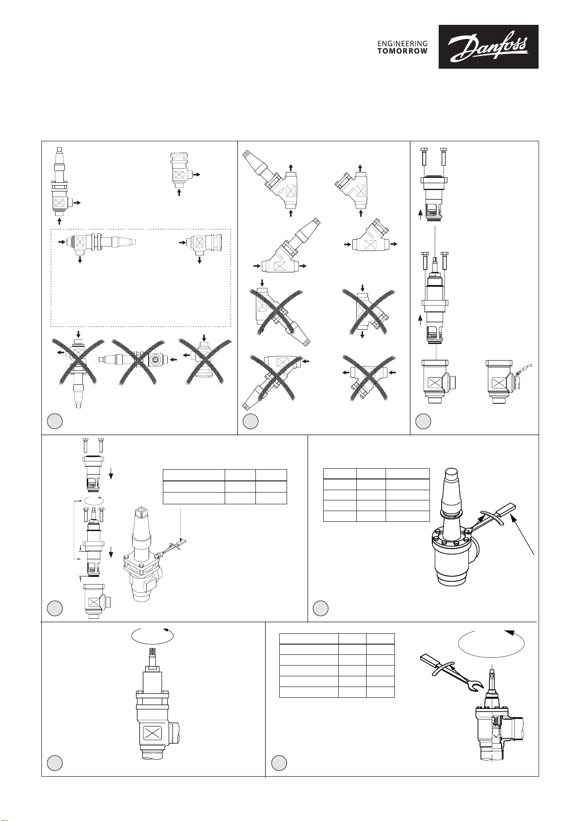
The valve must be installed with the spindle
on top vertically upwards or in horizontal
position (fig. 1). SCA-X valves should be
opened by hand without the use of tools
or other devices. The valve is designed to
withstand a high internal pressure. However,
the piping system should be designed
to avoid liquid traps and reduce the risk
of hydraulic pressure caused by thermal
expansion. It must be ensured that the valve
is protected from pressure transients like
“liquid hammer” in the system.
Flow direction
Direct the flow towards the cone as indicated
by an arrow on the valve housing (fig. 1).
Welding
The bonnet should be removed before
welding (fig. 2) to prevent damage to the
O-rings in the packing gland and the gasket
between the valve body and bonnet, as
well as the teflon gasket in the valve seat.
Be careful not to damage the teflon cone
ring and make sure the complete bonnet is
protected from dirt and water while removed.
Only materials and welding methods,
compatible with the valve housing material,
must be applied to the valve housing. The
valve housing must be free from stresses
(external loads) after installation.
The valve should be cleaned internally to
remove welding debris on completion of
welding and before the valve is reassembled.
Avoid welding debris and dirt in the threads
of the housing and the bonnet.
Do NOT remove or service the dark colored
grease between the spindle thread and
the bonnet. In case the grease has been
contaminated with dirt, debris, particles
or water the complete top part must be
replaced.
Stop check valves must not be mounted in
systems where the outlet side of the valve
is open to atmosphere. The outlet side of
the valve must always be connected to the
system or properly capped off, for example
with a welded-on end plate.
Assembly
Remove welding debris and any dirt from
pipes and valve body before assembly. Check
that the cone has been fully screwed back
towards the bonnet before it is repositioned
in the valve body (SCA DN 50-125) (fig. 3).
Important for the SCA-X valves:
Full capacity is only obtained when the
spindle is screwed outward, “into bonnet”, i.e.
counterclockwise (fig. 3).
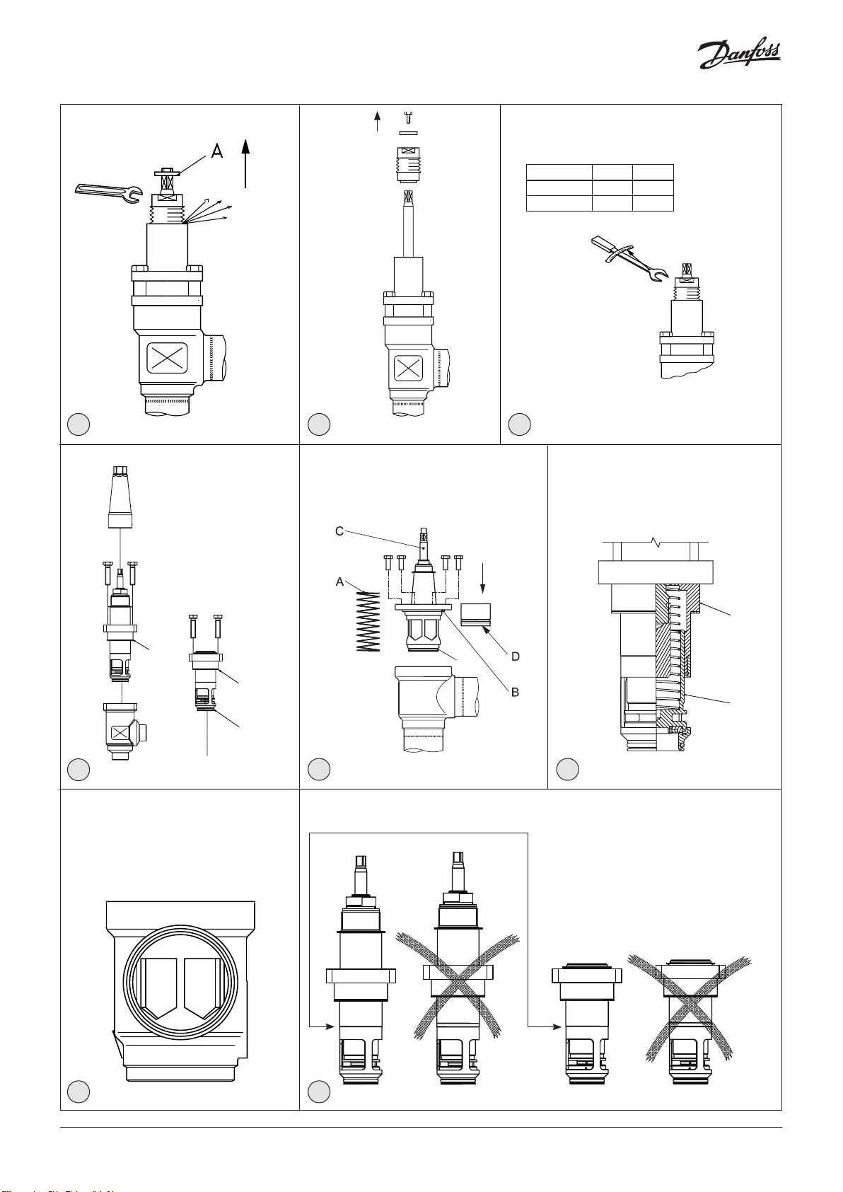
Tightening
Tighten the bonnet with a torque wrench, to
the values indicated in the table (fig. 3).
Please note that the table (fig. 3) containing
maximum torque must be adhered to and
never exceeded.
Important for SCA-X/CHV-X 50 - 125 valves:
For optimal flow the insert must be installed
as indicated in (fig. 10). Otherwise kv value
will be below indicated in the
technical brochure.
Colours and identification
The SCA-X and CHV-X valves are painted
with a red primer in the factory. Precise
identification of the valve is made via the
green coloured ID ring at the top of the
bonnet, as well as by the stamping on the
valve body. The external surface of the valve
housing must be protected against corrosion
with a suitable protective coating after
installation and assembly.
Protection of the name plate when repainting
the valve is recommended.
Maintenance
Packing gland (only SCA-X types)
When performing service and maintenance,
replace the complete packing gland only,
which is available as a spare part. As a
general rule, the packing gland must not be
removed if there is internal pressure in the
valve. However, if the following precautionary
measures are taken, the packing gland can be
removed with the valve still under pressure:
Backseating (fig. 4)
To backseat the valve, turn the spindle
counterclockwise until the valve is fully open.
Pressure equalization (fig. 5)
In some cases, pressure forms behind the
packing gland. Hence, a handwheel or a large
washer (pos. A) should be fastened on top of
the spindle while the pressure is equalized.
The pressure can be equalized by slowly
screwing out the gland.
Removal of packing gland (fig. 6)
Packing gland can now be removed.
Dismantling the valve (fig. 8)
Do not remove the bonnet while the valve is
still under pressure.
DN 15-40 (fig. 8a):
- Check that the gasket (pos. A+B) has not
been damaged.
- If the gasket (pos. A) has been exposed
to air or other refrigerants than listed in
this installation guide for more than
6 months it must be replaced.
- Check that the spindle is free of scratches
and impact marks.
- If the teflon cone ring has been damaged,
the whole cone assembly must be
replaced.
DN 50-125 (fig. 8b):
- Check that the spring (pos. A) is intact.
- Check that the gasket (pos. B+E) has not
been damaged.
- If the gasket (pos. A) has been exposed
to air or other refrigerants than listed in
this installation guide for more than
6 months it must be replaced.
- Check that the spindle (pos. C) is free of
scratches and impact marks.
- If the teflon cone ring (pos. D) has been
damaged, the whole cone assembly must
be replaced.
Replacement of the cone (fig. 9)
DN 15-40:
O-ring (pos. C) prevents the cone from falling
out. Pull the cone clear of the bonnet. Ensure
that the spring is not lost in the process.
Remove dirt, if any. Mount O-ring (pos. C) on
cone. Mount spring and cone in bonnet.
Do NOT remove or service the dark colored
grease between the spindle thread and
the bonnet. In case the grease has been
contaminated with dirt, debris, particles
or water the complete top part must be
replaced.
Assembly
Remove dirt, if any, from pipes and housing
before assembly. Important for the SCA-X
valves: Full capacity is only obtained when
the spindle is screwed outward, “into the
bonnet”, i.e. counterclockwise (fig. 3).
Note:
For SCA-X and CHV-X sizes DN 15-40 it
is important to ensure that the lower
and upper part of the insert is tightly
screwed together (fig. 11) and that this
screw connection is kept tight during
repositioning of the cone in the housing.
Use a to
rque wrench to tighten the bonnet
(fig. 3).
Tightening
Tighten the bonnet with a torque wrench,
to the values indicated in the table (fig. 3).
Tighten the packing gland with a torque
wrench, to the values indicated in the table
(fig. 7).
Use only original Danfoss parts, (including
packing glands and gaskets) for replacement.
Materials of new parts are certified for the
relevant refrigerant.
In cases of doubt, please contact your local
Danfoss sales office.
© Danfoss | DCS (MWA) | 2018.05
DKRCI.PI.FL1.T2.ML | 520H6172 | 4
Page 5
DEUTSCH
Installation
Refrigerants
Anwendbar für HFCKW, HFKW, R717
(Ammoniak), R744 (CO2), Propan, Butan, IsoButan und Ethan.
Das Ventil ist nur für die Verwendung in
geschlossenen Kreisläufen empfohlen. Für
weitere Informationen wenden Sie sich bitte
an Danfoss.
Temperaturbereich
–60/+150°C (–76/+302°F)
Druckbereich
Die Ventile sind für einen max. Betriebsdruck
von 52 bar (754 psi) ausgelegt.
Das Ventil muss mit der Spindel senkrecht
nach oben (Abb. 1) eingebaut werden.
SCA-X sollten per Hand ohne Werkzeug oder
andere Vorrichtungen geöffnet werden.
Das Ventil ist für einen hohen Innendruck
ausgelegt. Das Verrohrungssystem
sollte jedoch ausgelegt sein, um
Flüssigkeitseinschlüsse zu verhindern und
das Risiko von Hydraulikdruck, verursacht
durch Wärmeausdehnung, zu senken. Es
muss sichergestellt werden, dass das Ventil
vor Druckstößen wie Flüssigkeitsschlag im
System geschützt ist.
Durchflussrichtung
Die Ventile müssen mit dem Durchfluss zum
Kegel in Pfeilrichtung auf dem Ventilgehäuse
eingebaut werden (Abb. 1).
Schweißen
Das Oberteil sollte vor dem Schweißen
entfernt werden (Abb. 2), um eine
Beschädigung der O-Ringe in der
Stopfbuchse und der Dichtung zwischen dem
Ventilkörper und dem Oberteil sowie der
Teflondichtung im Ventilsitz zu vermeiden.
Achten Sie darauf, den Teflon-Konusring
nicht zu beschädigen, und stellen Sie sicher,
dass das komplette demontierte Oberteil vor
Schmutz und Wasser geschützt ist.
Es dürfen nur Materialien und
Schweißmethoden verwendet werden,
die mit dem Material des Ventilgehäuses
kompatibel sind. Das Ventilgehäuse muss
nach der Installation frei von externen
Spannungen sein (keine äußeren Lasten).
Reinigen Sie das Ventil vor dem erneuten
Zusammenbauen von innen, um evtl.
Schweißrückstände zu entfernen. Vermeiden
Sie Schweißrückstände und Schmutz in den
Gewindebohrungen des Gehäuses und des
Oberteils.
Das dunkle Schmierfett zwischen dem
Spindelgewinde und dem Ventiloberteil darf
NICHT entfernt oder gewartet werden. Falls
das Schmierfett durch Schmutz, Rückstände,
Partikel oder Wasser verunreinigt wurde,
muss das Oberteil vollständig ausgetauscht
werden.
Absperrrückschlagventile dürfen nicht in
Systemen verwendet werden, bei denen
die Austrittsseite des Ventils nach außen hin
offen ist. Die Austrittsseite des Ventils muss
immer an die Anlage angeschlossen oder
ordnungsgemäß abgedeckt sein, z. B. mit
einer angeschweißten Endplatte.
Zusammenbau
Vor dem Zusammenbau Schweißüberreste
und Schmutz von Rohrleitungen und
Ventilgehäuse entfernen. Sicherstellen,
dass der Kegel vollständig zum Ventildeckel
hin zurückgeschraubt wurde, bevor er im
Ventilgehäuse eingesetzt wird (Abb. 3).
Wichtiger Hinweis für die SCA-X Ventile:
Volle Kapazität wird nur erreicht, wenn die
Spindel nach außen „in den Deckel“, d.h.
gegen den Uhrzeigersinn geschraubt ist (Abb.
3).
Anziehen
Den Ventildeckel mit einem
Drehmomentschlüssel anziehen (Werte bitter
in der Tabelle 3 entnehmen.
Bitte beachten, dass es sich hierbei um
Maximalwerte handelt, die niemals
überschritten werden dürfen.
Farben und Kennzeichnungen
Die SCA-X und CHV-X Ventile werden ab
Werk mit Rotoxid grundiert. Eindeutige
Kennzeichnung des Ventils erfolgt über
den Kennring oben am Ventildeckel
sowie die Prägung am Ventilgehäuse. Die
Außenfläche des Ventilgehäuses muss nach
dem Einbau und dem Zusammenbau mit
einer geeigneten Schutzbeschichtung gegen
Korrosion geschützt werden.
Beim Neulackieren des Ventils wird der Schutz
des Kennschilds empfohlen
Wartung
Stopfbuchse (nur SCA-X)
Bei Service- und Wartungsarbeiten ist
immer nur die komplette Stopfbuchse
auszutauschen, die als Ersatzteil erhältlich
ist. Grundsätzlich darf die Stopfbuchse
nur bei drucklosem Ventil entfernt
werden. Unter Berücksichtigung folgender
Vorsichtsmaßnahmen kann die Stopfbuchse
jedoch auch von einem unter Druck
stehenden Ventil entfernt werden:
Rücksitzdichtung (Abb. 4)
Zur Aktivierung der Rücksitzdichtung des
Ventils, die Spindel gegen den Uhrzeigersinn
drehen bis das Ventil völlig offen ist.
Druckausgleich (Abb. 5)
Unter Umständen entsteht Druck hinter
der Stopfbuchse. Daher sollte, während der
Druck ausgeglichen wird, am Spindelkopf ein
Handrad oder Ähnliches befestigt sein.
Der Druck lässt sich dann durch langsames
Herausdrehen der Stopfbuchse ausgleichen.
Ausbau der Stopfbuchse (Abb. 6)
Die Kappe und Stopfbuchse können jetzt
entfernt werden.
Zerlegen des Ventils (Abb. 8)
Den Ventildeckel nicht entfernen, während
das Ventil noch unter Druck steht.
DN 15 – 40 (Abb. 8a)
- Sicherstellen, dass der O-Ring (Pos. A+B)
nicht beschädigt wurde.
- Wenn die Dichtung (Pos. A) länger als
sechs Monate der Luft oder Kältemitteln,
die nicht in dieser Installationsanleitung
aufgelistet sind, ausgesetzt war, muss sie
ausgetauscht werden.
- Sicherstellen, dass die Spindel (Pos. C)
frei von Kratzern und Stoßspuren ist.
- Ist der Teflonring am Kegel
beschädigt, ist die gesamte Kegeleinheit
auszutauschen.
DN 50 – 125 (Abb. 8b)
- Sicherstellen, dass die Feder (Pos. A)
intakt ist.
- Sicherstellen, dass der O-Ring (Pos. B+E)
nicht beschädigt wurde.
- Wenn die Dichtung (Pos. A) länger als
sechs Monate der Luft oder Kältemitteln,
die nicht in dieser Installationsanleitung
aufgelistet sind, ausgesetzt war, muss sie
ausgetauscht werden.
- Sicherstellen, dass die Spindel (Pos. C)
frei von Kratzern und Stoßspuren ist.
- Ist der Teflonring am Kegel (Pos. D)
beschädigt, ist die gesamte Kegeleinheit
auszutauschen.
Ersatz des Kegel (Abb. 9)
DN 15-40:
O-Ring (Pos. C) verhindert das Herausfallen
des Kegels. Ziehen Sie den Kegel von der
Ventiloberteil ab. Stellen Sie sicher, dass die
Feder dabei nicht verloren geht. Entfernen Sie
eventuell vorhandenen Schmutz. O-Ring (Pos.
C) auf Kegel montieren. Feder und Kegel in
Ventiloberteil montieren.
Das dunkle Schmierfett zwischen dem
Spindelgewinde und dem Ventiloberteil darf
NICHT entfernt oder gewartet werden. Falls
das Schmierfett durch Schmutz, Rückstände,
Partikel oder Wasser verunreinigt wurde,
muss das Oberteil vollständig ausgetauscht
werden.
Zusammenbau
Schmutz, falls vorhanden, vor dem
Zusammenbau von Rohrleitungen und
Gehäuse entfernen. Wichtiger Hinweis für
die SCA-X Ventile: Volle Kapazität wird nur
erreicht, wenn die Spindel nach außen „in
den Deckel“, d. h. gegen den Uhrzeigersinn
geschraubt ist (Abb. 3).
Hinweis
Für SCA-X und CVH-X 15-40 ist es wichtig
sicherzustellen, dass das Oberteil fest mit
dem Unterteil verschraubt ist (Abb. 11)
und das diese Schraubverbindung beim
Wiedereinsetzen des Konus in das Gehäuse
fest verschraubt bleiben.
Den Ventildeckel mit einem
Drehmomentschlüssel anziehen (Abb. 3).
Festspannen
Den Ventildeckel mit einem
Drehmomentschlüssel festspannen,
für diesbezügliche Werte siehe Tabelle
(Abb. 3). Die Stopfbuchse mit einem
Drehmomentschlüssel festspannen, für
diesbezügliche Werte siehe Tabelle (Abb. 7).
Zum Austausch nur Originalteile von Danfoss,
einschließlich Stopfbuchsen, O-Ringe und
Dichtungen, benutzen. Die Werkstoffe
von Neuteilen sind für das betreffende
Kältemittel zertifiziert.
Im Zweifelsfall bitte mit Danfoss Kontakt
aufnehmen.
© Danfoss | DCS (MWA) | 2018.05
DKRCI.PI.FL1.T2.ML | 520H6172 | 5
Page 6

FRANÇAIS
Installation
Fluides frigorigènes
Applicable aux fluides frigorigènes HCFC,
HFC, R717 (ammoniac), R744 (CO2), propane,
butane, isobutane et éthane.
Cette vanne est préconisée uniquement pour
les circuits fermés.
Pour plus d'informations, contactez Danfoss.
Plage de températures
-60/+150 °C
Plage de pressions
*52 bar
Installez la vanne de sorte que la tige se
trouve en position verticale ou horizontale
(fig. 1). Les vannes SCA-X doivent être
ouvertes
outils
conçues pour résister à une pression interne
élevée. Toutefois, il convient de concevoir le
circuit de façon à
réduire les risques de formation d’une
pression hydraulique sous l’effet de la
dilatation thermique. Veillez à ce que la vanne
soit protégée des variations de pression au
sein du circuit comme les « coups de bélier ».
Sens du débit
Dirigez le débit en direction du cône comme
indiqué par la flèche sur le corps de la vanne
(fig. 1).
Soudure
La partie interne doit être retirée avant le
soudage (fig. 2) afin de ne pas endommager
les joints toriques du presse étoupe, et le
joint entre le corps de vanne et la partie
supérieure, ainsi que le joint en téflon
du siège de la vanne. Veiller à ne pas
endommager la bague en téflon du cône.
Vérifier que la partie interne une fois retirée
est à l’abri de la saleté et de l’eau.
Seuls des matériaux et des méthodes de
soudage compatibles avec le matériau du
corps de la vanne, peuvent être soudés et
appliqués au corps de la vanne. Aucune
contrainte (charges externes) ne doit être
exercée sur le boîtier de la vanne après
l’installation.
L’intérieur de la vanne doit être nettoyé pour
éliminer les débris de soudage une fois le
soudage effectué et avant le montage de la
vanne. Éviter que des débris de soudage et
des salissures ne pénètrent dans les filetages
du boîtier et le capuchon.
Ne PAS enlever ou nettoyer l’excédent de
graisse foncée entre le filetage de la tige et
la partie interne. En cas de contamination
de la graisse par de la saleté, des débris, des
particules ou de l’eau, la partie supérieure
doit être entièrement remplacée.
Les clapets anti-retour ne doivent en aucun
cas être montés dans des systèmes où la
sortie de la vanne est exposée à l’air. Le côté
sortie de la vanne doit toujours être raccordé
au système ou correctement couvert, par
exemple à l’aide d’un embout soudé.
Montage
Retirez les résidus de soudure et les impuretés
des conduites et du corps de vanne avant de
procéder au montage. Vérifiez que le cône a
été entièrement revissé à l’arrière du
manuellement sans recourir à des
ou d’autres matériels. Ces vannes sont
éviter les pièges à liquide et
capuchon avant de le replacer dans le corps
de la vanne (SCA DN 50-125)
Informations importantes concernant les
vannes SCA-X :
La pleine capacité est obtenue uniquement
lorsque la tige est vissée vers l’extérieur
le capuchon », c'est-à-dire dans le sens
des aiguilles d'une montre (fig. 3).
Serrage
Serrez le capuchon à l’aide d’une clé
dynamométrique, conformément aux valeurs
indiquées dans le tableau (fig. 3).
Veuillez noter que la valeur de couple
maximale contenue dans le tableau (fig. 3)
doit être respectée et ne doit en aucun cas
être dépassée.
Informations importantes concernant les
vannes SCA-X/CHV-X 50 - 125 :
Pour un débit optimal, l’insert doit être installé
comme indiqué sur la fig. 10. Dans le cas
contraire, la valeur kv sera indiquée plus bas
dans la brochure technique.
Couleurs et identification
Les vannes SCA-X et CHV-X sont recouvertes en
usine
d’une couche de couleur primaire
rouge. La vanne peut être précisément
identifiée à l’aide de la bague d’identification
de couleur verte, située au sommet du
capuchon, ainsi que par un estampillage sur
le corps de la vanne.
La surface extérieure du corps de la vanne
doit être protégée de la corrosion à l’aide
revêtement adéquat appliqué après
l’installation et le montage.
Il est recommandé de protéger la plaque
signalétique lors de l’application de la
peinture sur la vanne.
(fig. 3).
« dans
inverse
d’un
Maintenance
Presse-étoupe (uniquement pour les
types SCA-X)
Lors des opérations de service et de
maintenance, remplacez uniquement le
presse-
étoupe complet, disponible en pièce
détachée.
ne doit pas être retiré lorsque la vanne est
sous pression. Toutefois, si les
précaution suivantes sont prises, il est possible
de remplacer le presse-étoupe pendant que la
vanne
Contre-siège (fig. 4)
Pour ouvrir la vanne, effectuez une rotation
de la tige dans le sens inverse des aiguilles
d'une montre jusqu'à ouverture complète de
la vanne.
Égalisation de la pression (fig. 5)
Dans certains cas, une pression se forme
derrière le presse-étoupe. C’est pourquoi un
volant de manœuvre ou un dispositif similaire
(pos. A) doit être fixé au sommet de la tige
pendant l’égalisation
pression peut être
progressivement le presse-étoupe.
Dépose du presse-étoupe (fig. 6)
Le presse-étoupe peut maintenant être retiré.
Démontage de la vanne (fig. 8)
Ne jamais retirer le capuchon si la vanne est
encore
En règle générale, le presse-étoupe
mesures de
est sous pression :
de la pression. La
égalisée en
sous pression.
dévissant
DN 15-40 (fig. 8a) :
- Vérifiez que le joint d'étanchéité (pos. A+B)
n'a pas été endommagé.
- Si le joint d’étanchéité (pos. A) est resté
à l’air libre ou s’il a été exposé à d’autres
fluides frigorigènes que ceux mentionnés
dans ce guide d’installation pendant plus
de 6 mois, il doit être remplacé.
- Vérifiez que la tige est exempte de rayures
de traces d’impacts.
- Si la bague du cône en téflon a été
endommagée, remplacez le cône entier.
DN 50-125 (fig. 8b) :
- Vérifiez que le ressort (pos. A) est intact.
- Vérifiez que le joint d'étanchéité (pos. B+E)
n'a pas été endommagé.
- Si le joint d’étanchéité (pos. A) est resté
à l’air libre ou s’il a été exposé à d’autres
fluides frigorigènes que ceux mentionnés
dans ce guide d’installation pendant plus
de 6 mois, il doit être remplacé.
- Vérifiez que la tige (pos. C) est exempte de
rayures et de marques d'impacts.
- Si la bague du cône en téflon (pos. D) a
endommagée, le cône entier doit être
remplacé.
Remplacement du cône (fig. 9)
DN 15-40
Le joint torique (pos. C) évite au cône de
tomber. Dégagez le cône du capuchon. Veillez
à
ne pas perdre le ressort au cours du processus.
Éliminez les impuretés si besoin. Montez le
joint torique (pos. C) sur le cône. Montez le
ressort et le cône dans le capot.
Ne PAS enlever ou nettoyer l’excédent de
graisse foncée entre le filetage de la tige et
la partie interne. En cas de contamination
de la graisse par de la saleté, des débris, des
particules ou de l’eau, la partie supérieure
doit être entièrement remplacée.
Montage
Avant le montage, retirez si besoin les
impuretés des tuyauteries et du corps.
Information importante concernant les
vannes SCA-X : la pleine capacité est
uniquement obtenue lorsque la tige est
vissée vers l’extérieur « dans le capuchon »,
c'est-à-dire dans le sens inverse des aiguilles
d’une montre (fig. 3).
Remarque :
dans le cas des vannes SCA-X et CHV-X,
tailles DN 15-40, il est important de vous
assurer que les parties inférieure et
supérieure de l’insert sont correctement
vissées ensemble (fig. 11) et que leur
raccord est fermement maintenu lors du
repositionnement du cône dans le corps.
Utilisez une clé dynamométrique pour serrer
le capuchon (fig. 3).
Serrage
Serrez le capuchon à l’aide d’une clé
dynamométrique, conformément aux valeurs
indiquées dans le tableau (fig. 3). Serrez le
presse-étoupe à l’aide d’une clé
dynamométrique, conformément aux valeurs
indiquées dans le tableau (fig. 7).
N’utilisez que des composants Danfoss
d’origine, en particulier pour tout
remplacement du presse-étoupe ou des joints
d’étanchéité. Les matériaux des nouveaux
composants sont homologués
frigorigène utilisé.
En cas de doute, veuillez prendre contact avec
Danfoss.
pour le fluide
et
été
© Danfoss | DCS (MWA) | 2018.05
DKRCI.PI.FL1.T2.ML | 520H6172 | 6
Page 7

ESPAÑOL
Instalación
Refrigerantes
Aptas para HCFC, HFC, R-717 (amoníaco),
R-744 (CO2), propano, butano, isobutano y etano.
Se recomienda limitar el uso de estas válvulas a
circuitos cerrados. Si desea obten er más
información, póngase en contacto con Danfoss
Rango de temperatura
De –60 a +150 °C (de –76 a +302 °F).
Rango de presión
52 bar (754 psi).
La válvula debe instalarse de forma que el eje
quede en posición vertical y orientado hacia
arriba o en posición horizontal (consulte la fig. 1)
Las válvulas SCA-X deben abrirse manualmente,
sin hacer uso de herramientas u otros
dispositivos. Son válvulas diseñadas para
soportar
Sin embargo, el sistema de tuberías debe
diseñarse de tal forma que se eviten las
acumulaciones de líquido y se reduzca el riesgo
asociado a la presión
expansión térmica. Debe garantizarse que
la válvula se encuentre protegida frente a los
fenómenos transitorios
puedan producirse en el sistema (por ejemplo, el
fenómeno conocido como “golpe de ariete”).
Dirección del caudal
El caudal debe dirigirse hacia el cono, de acuerdo
con lo indicado por la flecha de
válvula (consulte la fig. 1).
Soldadura
La parte superior de la válvula debe
desmontarse antes de realizar la soldadura (fig.
2) con el fin de evitar que se produzcan daños en
las juntas tóricas del prensaestopas y en la junta
situada entre el cuerpo y la parte superior de la
válvula, así como en la junta de teflón del asiento
de la válvula. Tenga cuidado de no dañar el anillo
cónico de teflón y asegúrese de proteger toda
la parte superior de la válvula de la suciedad y el
agua al extraerla.
Los materiales y métodos de soldadura aplicados
al cuerpo de la válvula deberán ser compatibles
con el material de este. El cuerpo de la válvula
no debe someterse a tensiones (cargas externas)
tras su instalación.
Al finalizar la soldadura y antes de volver a
montar la válvula, deberá limpiarse el interior
de esta para eliminar los restos de soldadura. No
deben quedar restos de materiales de soldadura
ni suciedad en las roscas del cuerpo y la parte
superior de la válvula.
NO elimine ni sustituya la grasa de color oscuro
que se encuentra entre el eje roscado y la parte
superior de la válvula. Si la grasa se contamina
con suciedad, residuos, partículas o agua, deberá
sustituirse toda la parte superior.
No deberán montarse válvulas de cierre y
retención en sistemas en los que el lado de
salida de la válvula quede abierto a la atmósfera.
El lado de salida de la válvula siempre debe
conectarse al sistema o cerrarse debidamente
(por ejemplo, soldando una placa).
Montaje
Elimine los restos de materiales de soldadura
y la suciedad de las tuberías y el cuerpo de
la válvula antes de proceder a su montaje.
Compruebe que el cono se encuentre
completamente enroscado en el casquillo antes
de volver a acoplarlo al cuerpo de la válvula (SCA
DN 50-125) (consulte la fig. 3).
una presión
interna elevada.
hidráulica generada por la
asociados a la presión
la carcasa de la
.
.
que
Nota importante en relación con las válvulas
SCA-X:
Únicamente puede alcanzarse la capacidad
máxima si el eje se enrosca hacia fuera (esto es,
hacia el casquillo), es decir, en sentido
antihorario (consulte la fig. 3).
Apriete
Apriete el casquillo empleando una llave
dinamométrica y aplicando los valores de
par de apriete especificados en la tabla (consulte
la fig. 3).
Tenga en cuenta que deben respetarse los
valores de par de apriete máximos indicados en la
tabla (consulte la fig. 3), sin superarlos en
ningún caso.
Nota importante en relación con las válvulas
SCA-X y CHV-X de tamaños DN 50-125:
Para conseguir un caudal óptimo, la pieza debe
instalarse según se indica en la fig. 10. De lo
contrario, el valor kv será inferior al indicado en
el folleto técnico.
Colores e identificación
Las válvulas SCA-X y CHV-X reciben una
imprimación de color rojo durante su
fabricación. La identificación precisa de dichas
válvulas se lleva a cabo por medio de un anillo
característico de color verde situado en la parte
superior del casquillo, así como de la
estampación del cuerpo de
La superficie externa de la carcasa de las válvulas
debe protegerse frente a la corrosión aplicando
recubrimiento protector adecuado tras su
instalación y montaje.
Se recomienda proteger la placa de
características antes de pintar la válvula.
las válvulas.
un
Mantenimiento
Prensaestopas (sólo para válvulas SCA-X)
Sólo es preciso sustituir el conjunto del
prensaestopas como parte de las operaciones
servicio y mantenimiento; este elemento se
encuentra disponible como pieza de repuesto.
Como norma general, el prensaestopas no debe
desmontarse si el interior de la válvula se
encuentra
las
puede desmontarse aunque
la válvula se encuentre presurizada:
Sellado interno (consulte la fig. 4)
Para sellar internamente la válvula, gire el eje en
sentido antihorario hasta que la válvula quede
completamente abierta.
Igualación de presión (consulte la fig. 5)
En algunos casos, puede producirse una
acumulación de presión tras el prensaestopas
Debido a ello, debe acoplarse un volante o una
arandela grande a la parte superior del eje (pos.
A) mientras la presión se iguala.
La presión puede igualarse desenroscando
lentamente el prensaestopas.
Desmontaje del prensaestopas (consulte la
fig. 6)
Una vez llevados a cabo los pasos anteriores,
puede desmontarse el prensaestopas.
Desensamblaje de la válvula (consulte la
fig. 8)
No desmonte el casquillo mientras la válvula se
encuentre presurizada.
DN 15-40 (consulte la fig. 8a):
- Compruebe que la junta (pos. A+B) no
- Si la junta (pos. A) ha estado expuesta
presurizado. No obstante, si se adoptan
precauciones
presente daños.
al aire o a refrigerantes no indicados
en esta guía de instalación durante más de
seis meses, deberá sustituirla.
siguientes, el
prensaestopas
de
.
- Compruebe que el eje no presente arañazos
marcas de golpes por impacto.
- Si el anillo de teflón del cono ha sufrido daños,
deberá sustituir el conjunto del cono.
DN 50-125 (consulte la fig. 8b):
- Compruebe que el muelle (pos. A) esté
intacto.
- Compruebe que la junta (pos. B+E) no
presente daños.
- Si la junta (pos. A) ha estado expuesta
al aire o a refrigerantes no indicados
en esta guía de instalación durante más de
seis meses, deberá sustituirla.
- Compruebe que el eje (pos. C) no presente
arañazos ni marcas de golpes por impacto.
- Si el anillo de teflón del cono (pos. D) ha
sufrido daños, deberá sustituir el conjunto
cono.
Sustitución del cono (consulte la fig. 9)
DN 15-40:
La junta tórica (pos. C) impide que el cono pueda
desprenderse. Tire del cono hasta separarlo del
casquillo. Compruebe que el
separado durante el proceso. Limpie la suciedad
que pueda existir. Monte la junta tórica (pos. C) en
el cono. Monte el muelle y el cono en el
casquillo.
NO elimine ni sustituya la grasa de color oscuro
que se encuentra entre el eje roscado y la parte
superior de la válvula. Si la grasa se contamina
con suciedad, residuos, partículas o agua, deberá
sustituirse toda la parte superior.
Montaje
Antes de proceder a realizar el montaje, limpie la
suciedad que pueda existir en las tuberías
y la carcasa. Nota importante en relación con
válvulas SCA-X: Únicamente puede alcanzarse
capacidad máxima si el eje se enrosca hacia
fuera (esto es, hacia el casquillo), es decir,
en sentido antihorario (consulte la fig. 3).
Nota:
Para válvulas SCA-X y CHV-X de tamaños DN
15-40, es importante garantizar que las
partes inferior y superior del módulo queden
bien sujetas al enroscarlas (consulte la fig. 11)
y que la conexión roscada se mantenga
apretada al volver a instalar el cono en la
carcasa.
Emplee una llave dinamométrica para apretar el
casquillo (consulte la fig. 3).
Apriete
Apriete el casquillo empleando una llave
dinamométrica y aplicando los valores de par de
apriete especificados en la tabla (consulte la fig.
3). Apriete el prensaestopas empleando una
llave dinamométrica y aplicando los valores de
par de apriete especificados en la tabla (consulte
la fig. 7).
Use únicamente piezas de repuesto originales
fabricadas por Danfoss (incluidos los
prensaestopas y las juntas). Los materiales con
los que se fabrican las piezas de repuesto
poseen las homologaciones pertinentes para el
refrigerante correspondiente.
En caso de duda, póngase en contacto con su
distribuidor local de Danfoss.
muelle no se ha
ni
del
las
la
© Danfoss | DCS (MWA) | 2018.05
DKRCI.PI.FL1.T2.ML | 520H6172 | 7
Page 8

ITALIANO
Installazione
Refrigeranti
Applicabile a HCFC, HFC, R717 (ammoniaca),
R744 (CO2), propano, butano, isobutano ed
etano.
La valvola è raccomandata solo per l'utilizzo in
circuiti chiusi. Per ulteriori informazioni,
contattare Danfoss.
Campo temperatura
–60/+150°C (–76/+302°F)
Campo di pressione
52 bar (754 psi)
La valvola deve essere installata con lo stelo
sulla parte superiore, rivolto verticalmente
verso l'alto o in posizione orizzontale (fig. 1). Le
valvole SCA-X devono essere aperte
manualmente senza l'ausilio di attrezzi o altri
dispositivi. La valvola è progettata per
tollerare pressioni interne estremamente
elevate. Tuttavia, il sistema di tubazioni deve
essere progettato per prevenire trappole di
liquido e ridurre il rischio di una pressione
idraulica causata dall'espansione termica.
È necessario assicurarsi che la valvola sia
protetta da transitori di pressione come
i "colpi d'ariete".
Direzione del flusso
Dirigere il flusso verso il cono, come indicato
dalla freccia sull'involucro della valvola (fig. 1).
Saldatura
Il coperchio deve essere rimosso prima della
saldatura (fig. 2) per prevenire danni agli
o-ring nel premistoppa, alla guarnizione
fra il corpo valvola e il coperchio e alla
guarnizione in teflon nella sede della valvola.
Fare attenzione a non danneggiare l’anello in
teflon del cono e assicurarsi che il coperchio
sia protetto per intero da sporcizia e acqua in
fase di rimozione.
Solo materiali e metodi di saldatura
compatibili con il materiale dell’involucro
della valvola devono essere applicati
all’involucro della valvola. L’involucro della
valvola deve essere esente da sollecitazioni
(carichi esterni) dopo l’installazione.
La valvola deve essere pulita internamente
per rimuovere i detriti della saldatura al
completamento dell’operazione e prima che
la valvola sia rimontata. Evitare che detriti
di saldatura e sporcizia si depositino nelle
filettature dell’involucro e del coperchio.
NON rimuovere né intervenire sul grasso
scuro tra la filettatura dell’asta e il coperchio.
Nel caso in cui il grasso sia stato contaminato
da sporco, detriti, particelle o acqua, è
necessario sostituire interamente la parte
superiore.
Valvole di intercettazione/ritegno non
devono essere montate in impianti in
cui il lato uscita della valvola sia esposto
all’atmosfera. Il lato uscita della valvola
deve sempre essere collegato all’impianto o
correttamente bloccato, ad esempio saldando
una piastra terminale.
Montaggio
Rimuovere i residui di saldatura e lo sporco dai
tubi e dal corpo valvola prima del montaggio.
Verificare che il cono sia stato completamente
avvitato in direzione del coperchio prima che
venga riposizionato nel corpo valvola
50-125) (fig. 3).
Importante per le valvole SCA-X:
È possibile ottenere una capacità piena solo
quando lo stelo è avvitato verso l'esterno,
coperchio", vale a dire in senso antiorario
3).
Serraggio
Serrare il coperchio con una chiave
dinamometrica, ai valori indicati nella tabella
(fig. 3).
Notare che è sempre necessario rispettare le
coppie massime riportate nella tabella (fig. 3);
le coppie massime non devono essere mai
superate.
Importante per le valvole SCA-X/CHV-X 50 125:
Per una portata ottimale, l'inserto deve essere
installato come indicato nella (fig. 10). In caso
contrario, il valore kv sarà inferiore a quello
indicato nella brochure tecnica.
Colori e identificazione
Le valvole SCA-X e CHV-X sono pitturate
con un primer rosso in fabbrica.
Un'identificazione precisa della valvola è
possibile tramite l'anello di identificazione
verde sulla parte superiore del coperchio e
tramite la stampigliatura sul corpo valvola. La
superficie esterna dell'involucro della valvola
deve essere protetta contro la corrosione con
un rivestimento protettivo idoneo dopo
l'installazione e il montaggio.
Si raccomanda di proteggere la targhetta
quando la valvola viene riverniciata.
(SCA DN
"nel
(fig.
Manutenzione
Guarnizione premistoppa (solo tipi SCA-X)
Quando si effettua un intervento di
riparazione o manutenzione, sostituire
solo il premistoppa completo, disponibile
come ricambio. Come regola generale, il
premistoppa non deve essere rimosso se
pressione interna è presente nella valvola.
Tuttavia, se ci si attiene alle seguenti misure
cautelative, il premistoppa può essere rimosso
con la valvola ancora sotto pressione:
Controtenuta (fig. 4)
Per posizionare la valvola in controtenuta,
ruotare lo stelo in senso antiorario fino a
quando la valvola non è completamente
aperta.
Equalizzazione della pressione (fig. 5)
In alcuni casi, la pressione si accumula dietro al
premistoppa. Un volantino o una rondella
grande (pos. A ) devono essere quindi fissati
sulla parte superiore dello stelo mentre la
pressione è equalizzata. La pressione può
essere equalizzata avvitando lentamente il
premistoppa.
Rimozione del premistoppa (fig. 6)
Il premistoppa può essere ora rimosso.
Smontaggio della valvola (fig. 8)
Non rimuovere il coperchio mentre la valvola
ancora sotto pressione.
DN 15-40 (fig. 8a):
- Controllare che la guarnizione (pos. A+B)
non abbia subito danni.
- Se la guarnizione (pos. A) è stata
esposta all’aria o ad altri refrigeranti
non menzionati nella presente guida
all’installazione per più di sei mesi,
dovrà essere sostituita.
- Verificare che lo stelo sia privo di graffi e
segni di impatto.
- Se l'anello in teflon del cono è danneggiato,
l'intero gruppo cono deve essere sostituito.
DN 50-125 (fig. 8b):
- Controllare che la molla (pos. A) sia intatta.
- Controllare che la guarnizione (pos. B+E)
non abbia subito danni.
- Se la guarnizione (pos. A) è stata
esposta all’aria o ad altri refrigeranti
non menzionati nella presente guida
all’installazione per più di sei mesi,
dovrà essere sostituita.
- Verificare che lo stelo (pos. C) sia privo di
graffi e segni di impatto.
- Se l'anello in teflon del cono (pos. D) è
danneggiato, l'intero gruppo cono deve
essere sostituito.
Sostituzione del cono (fig. 9)
DN 15-40:
L'o-ring (pos. C) previene la fuoriuscita del
cono. Rimuovere il cono dal coperchio.
Assicurarsi di non perdere la molla nel
processo. Rimuovere eventuale sporco.
Montare l'o-ring (pos. C) sul cono. Montare la
molla e il cono nel coperchio.
NON rimuovere né intervenire sul grasso
scuro tra la filettatura dell’asta e il coperchio.
Nel caso in cui il grasso sia stato contaminato
da sporco, detriti, particelle o acqua, è
necessario sostituire interamente la parte
superiore.
Montaggio
Rimuovere eventuale sporco dai tubi e
l'involucro prima dell'assemblaggio.
Importante per le valvole SCA-X: è possibile
ottenere una capacità piena solo quando lo
stelo è avvitato verso l'esterno, "nel coperchio",
vale a dire in senso antiorario (fig. 3).
Nota:
Per le SCA-X e CHV-X DN 15-40, è
importante assicurarsi che la parte inferiore
e la parte superiore dell’inserto siano ben
avvitate insieme (fig. 11) e che questa
connessione a vite sia mantenuta ben
serrata durante il riposizionamento del
cono nell’alloggiamento.
Utilizzare una chiave dinamometrica per
serrare il coperchio (fig. 3).
Serraggio
Serrare il coperchio con una chiave
dinamometrica, ai valori indicati nella tabella
(fig. 3). Serrare il premistoppa con una chiave
dinamometrica, ai valori indicati nella tabella
(fig. 7).
Utilizzare solo parti originali Danfoss
(compresi i premistoppa e le guarnizioni) per
la sostituzione. I materiali dei nuovi
componenti sono certificati per il refrigerante
pertinente.
In caso di dubbio, contattare l'ufficio vendite
Danfoss di zona.
è
© Danfoss | DCS (MWA) | 2018.05
DKRCI.PI.FL1.T2.ML | 520H6172 | 8
Page 9

中文
安装
制冷剂
适用于 HCFC、HFC、R717(氨),
R 744 (CO 2)、丙烷、丁烷、异丁烷和乙
烷。
阀门应使用在密封的制冷系统内部。如需
了解更多详细信息请联系丹佛斯 。
温度范围
–60/+150°C (–76/+302°F)
压力范围
52 bar (754 psi)
安装该阀门时,需保证阀杆垂直向上。(图
1)。SCA-X 截止止回阀应手动打开,不能使
用工具或其他装置。该阀门的设计可以承
受很高的内部压力。尽管如此,管路系统
的设计也必须避免有存液弯
现因热膨胀导致的过高压力而损坏管路。管
路的设计应考虑对系统中出现瞬时“液击
现象的有效防护。
流向
流向应按照阀体上箭头所示的阀芯指向
(图1)。
焊接
在焊接之前应取下阀盖(图2),防止对填
料中的O型环、阀体和阀盖之间的垫圈、阀
座内的特氟龙垫圈造成损坏。 请小心,不
要损坏特氟龙阀芯,并确保阀盖在取下时不
会沾到土和水。
只有与阀体材料相兼容的材料和焊接方法才
能用于阀体。 安装完毕后,阀体不得再承
受任何压力(外部负载)。
焊接结束后且在重新装配阀门之前,应当清
洗阀门内部,以清除焊接碎屑。 避免外壳
和阀盖的螺纹上沉积焊接碎屑和灰尘。
切勿清除或维护主轴螺纹和阀盖之间的深色
油脂。 因为油脂已被土、杂质、颗粒物或
水污染,必须更换整个顶部零件。
截止止回阀不得安装在阀门出口侧与大气联
通。 阀门出口侧必须始终与系统连接或密
封,例如与焊接端板。
装配
装配前请清理管道和阀体内的焊渣及污
垢。检查阀锥在阀体内被重新放置之前,
已经完全向阀帽方向拧回 (SCA DN 50-
125) (图3)。
SCA-X
截止止回阀注意事项
只有当轴向外拧“入阀帽”,即逆时针方
向时才能获得完全容量(图3)。
紧固
使用扭矩扳手拧紧螺帽,并达到表中规定
的数值(图3)。
请务必遵守包含最大扭矩的该表(图3),
切勿超过。
,防止系统出
”
SCA-X/CHV-X 50 - 125 阀门注意事项:
如需获得最佳流量,插入物必须按照图10
中的指示安装。否则,kv值将低于技术手
册中的规定。
彩色和标识
SCA-X 和 CHV-X 值在工厂中使用红色底漆粉
刷。通过阀帽顶部的绿色 ID 环和阀体上的
冲压可以准确识别阀门。安装和组装后,
阀套外表面必须使用适当的保护层防止
腐蚀。
重新粉刷阀门时建议对铭牌进行保护。
维护
填 料( 仅 用 于 S C A - X 型 )
在进行维修和维护时,仅更换作为备件的
整套填料。一般来说,如果阀门内有内部
压力,不得移除填料。但是,如果采取以
下预防措施,可以在阀门处于压力下时移
除填料。
后 座( 图 4 )
如需将阀门置于后座,应逆时针转动轴,
直至阀门完全打开。
压 力 均 衡( 图 5 )
在某些情况下,压力在填料后形成。因此
应在压力处于平衡时拧紧轴顶部的手轮或
大垫圈(位置A)。可以通过慢慢拧出填料
使压力均衡。
移 除 填 料( 图 6 )
现在可以清除填料。
拆 卸 阀 门( 图 8 )
请勿在阀门处于压力下时移除阀帽。
DN 15-40(图8a):
- 检查垫圈(位置A+B)是否受到损坏。
- 如果垫片(位置 A)暴露在空气或安装
指导列表之外的制冷剂中超过 6 个月,
则必须更换。
- 检查轴是否有刮伤或撞击痕迹。
-
如果特氟龙阀板受损,必须更换整个阀
芯。
DN 50-125(图8b):
- 检查弹簧(位置 A)是否完好无损。
- 检查垫圈(位置 B+E)是否受到损坏。
- 如果垫片(位置 A)暴露在空气或安装
指导列表之外的制冷剂中超过 6 个月,
则必须更换。
- 检查轴(位置 C)是否有刮伤或撞击痕
迹。
- 如果特氟龙阀板(位置 D
)受损,必须更
换整个阀芯。
更 换 芯( 图 9 )
DN 15-40:
O 形圈(位置 C)可以防止阀锥脱落。将阀
锥拉离阀帽。确保弹簧在此过程中没有丢
失。清除所有灰尘。在阀芯上安装 O 形圈(
位置 C
)。在阀帽内安装弹簧和阀芯。
切勿清除或维护主轴螺纹和阀盖之间的深色
油脂。 因为油脂已被土、杂质、颗粒物或水
污染,必须更换整个顶部零件。
,
装配
在组装之前应清除管道和阀套上的所有异
物。SCA-X 阀门注意事项:只有当轴向外
拧“入阀帽”,即逆时针方向时才能获得
完全容量(图3)。
注意:
对于 SCA-X 和 CHV-X 尺寸的 DN 15-40,
必须确保插入体上下部分已紧紧旋在了一起
(图 11),且在壳体内重新放置阀锥的过程
中,螺丝接口必须一直保持紧密。
使用扭矩扳手拧紧阀帽 (图3)。
紧固
使用矩扳手拧紧螺帽,并达到表中规定的
数值(图3)。使用扭矩扳手拧紧填料,并达
到表中规定的数值(图7)。
请使用丹佛斯原厂的配件,(包括填料和垫
圈)进行更换。更换备件请提前确认新备件
的材质是 否适用于相关制冷剂。
如有任何疑问,请联系当地丹佛斯当地办事
处。
© Danfoss | DCS (MWA) | 2018.05
DKRCI.PI.FL1.T2.ML | 520H6172 | 9
Page 10

POLSKI
Montaż
Czynniki chłodnicze
Dotyczy czynników chłodniczych: HCFC, HFC,
R717 (amoniak), R744 (CO2), propan, butan,
izobutan i etan.
Zawory te zaleca się stosować wyłącznie
w obiegach
informacji, skontaktuj się z firmą Danfoss.
Zakres temperatur
-60/+150°C (-76/+302°F)
Zakres ciśnień
Maksymalne ciśnienie robocze zaworów
wynosi 52 bary (754 psi)
Zawór należy zamontować z wrzecionem
skierowanym pionowo do góry lub w pozycji
poziomej (rys. 1). Zawory należy otwierać
ręcznie.
wytrzymał
rurociągów
aby uniknąć zamkniętych przestrzeni
cieczowych i zmniejszyć ryzyko wzrostu
ciśnienia spowodowanego
cieplną. Należy zapewnić ochronę zaworu
przed impulsami wysokiego
wynikającymi z uderzeń hydraulicznych.
Kierunek przepływu
Przepływ powinien być skierowany
grzybek, zgodnie ze strzałką
korpusie zaworu (rys. 1).
Spawanie
Przed spawaniem należy zdjąć pokrywę
zaworu (rys. 2), aby zapobiec uszkodzeniu
pierścieni O-ring w dławnicy oraz uszczelki
pomiędzy korpusem a pokrywą zaworu,
a także teflonowej uszczelki w gnieździe
zaworu. Należy zachować ostrożność, aby
nie uszkodzić teflonowego pierścienia
stożkowego, oraz upewnić się, czy podczas
demontażu pokrywa jest chroniona przed
kurzem i wodą.
Do spawania obudowy zaworu można
stosować tylko materiały i metody spawania
zgodne z materiałem obudowy. Po
montażu korpus zaworu nie może podlegać
zewnętrznym naprężeniom mechanicznym.
Po zakończeniu spawania, przed złożeniem
zaworu należy oczyścić wnętrze zaworu z
zanieczyszczeń mechanicznych po spawaniu.
Nie pozostawiać okruchów spawalniczych
ani zanieczyszczeń w gwintach korpusu i
pokrywy.
NIE należy usuwać ani poprawiać warstwy
ciemnego smaru między gwintem wrzeciona
a pokrywą. Jeśli smar został zanieczyszczony
kurzem, okruchami spawalniczymi, innymi
cząstkami lub wodą, należy wymienić całą
górną część.
Zawory zwrotne nie mogą być montowane
w instalacjach, w których wylotowa część
zaworu jest otwarta do atmosfery. Wylot
zaworu musi być zawsze podłączony do
instalacji lub należycie zaślepiony np.
przyspawaną dennicą.
Montaż elementów zaworu
Przed złożeniem zaworu należy usunąć z rur
oraz z korpusu zaworu okruchy spawalnicze
i wszelkie zanieczyszczenia. Przed zmianą
pozycji grzybka w korpusie zaworu upewnić
zamkniętych. Aby uzyskać więcej
Zawór został tak zaprojektowany, aby
wysokie ciśnienie. Jednak układ
powinien być zaprojektowany tak,
rozszerzalnością
ciśnienia
umieszczoną na
pod
się, że grzybek jest całkowicie wykręcony w
stronę pokrywy
Ważne dla zaworów SCA-X:
Pełną wydajność zaworu można uzyskać
wyłącznie wtedy, gdy wrzeciono jest
wykręcony do oporu w lewo (rys. 3).
Dokręcenie
Dokręcić pokrywę kluczem dynamometrycznym
momentem podanym w tabeli (rys. 3).
Należy pamiętać, aby zawsze przestrzegać
i nigdy nie przekraczać maksymalnego
momentu podanego w tabeli (rys. 3).
Ważne dla zaworów SCA-X/CHV-X 50 - 125:
Dla zapewnienia optymalnego przepływu
wkładka musi zostać zamontowana tak, jak
pokazano na rysunku (rys. 10). W przeciwnym
razie wartość kv będzie poniżej wartości
podanej w dokumentacji technicznej.
Kolory i identyfikacja
Zawory SCA-X i CHV-X malowane są w fabryce
czerwonym podkładem gruntującym. Zawór
można
precyzyjnie zidentyfikować za pomocą
zielonego
znajdującego się na górze pokrywy oraz
cechy numeratora na korpusie zaworu. Po
złożeniu i zamontowaniu zaworu, należy go
zabezpieczyć przed korozją pokrywając
odpowiednią powłoką ochronną.
Przed przystąpieniem do malowania
zaworu
identyfikacyjnego.
(SCA DN 50-125)
pierścienia identyfikacyjnego
zaleca się zabezpieczenie pierścienia
(rys. 3).
Serwis
Dławnica (wyłącznie typ SCA-X)
Podczas wykonywania prac serwisowych
należy wymieniać wyłącznie kompletną
dławnicę, która jest dostępna jako
część
zapasowa. Generalnie nie wolno
wymontowywać
zaworu panuje ciśnienie. Jeśli jednak zostaną
podjęte poniższe środki zapobiegawcze,
będzie można wymontować dławnicę
z zaworu, wewnątrz którego panuje ciśnienie.
Pełne wykręcenie wrzeciona (rys. 4)
Aby całkowicie wykręcic wrzeciono należy
obracać go w lewo, do oporu.
Wyrównywanie ciśnień (rys. 5)
W niektórych przypadkach pod dławnicą
tworzy się ciśnienie. W związku z tym przed
wyrównywaniem ciśnień należy przymocować
pokrętło lub dużą podkładkę (poz. A) na górnym
końcu wrzeciona. Ciśnienia można wyrównać
poprzez powolne wykręcanie dławnicy.
Demontaż dławnicy (rys. 6)
Można teraz zdemontować dławnicę.
Demontaż elementów zaworu (rys. 8)
Nie demontowywać pokrywy, gdy wewnątrz
zaworu nadal panuje ciśnienie.
DN 15-40 (rys. 8a):
- Sprawdzić, czy uszczelka (poz. A+B) nie
jest uszkodzona.
- Jeżeli uszczelka (poz. A) została
wystawiona na działania powietrza lub
czynników chłodniczych innych niż
wymienione w tej instrukcji instalacji
przez czas dłuższy niż 6 miesięcy,
wówczas należy ją wymienić.
- Sprawdzić, czy na wrzecionie nie ma
zarysowań i/lub śladów uderzeń.
dławnicy, gdy wewnątrz
- Jeśli uszkodzony jest teflonowy pierścień
grzybka, należy wymienić cały zespół
grzybka.
DN 50-125 (rys. 8b):
- Sprawdzić, czy sprężyna (poz. A) jest
nienaruszona.
- Sprawdzić, czy uszczelka (poz. B+E) nie jest
uszkodzona.
- Jeżeli uszczelka (poz. A) została
wystawiona na działania powietrza lub
czynników chłodniczych innych niż
wymienione w tej instrukcji instalacji
przez czas dłuższy niż 6 miesięcy,
wówczas należy ją wymienić.
- Sprawdzić, czy na trzpieniu (poz. C) nie ma
zarysowań i/lub śladów uderzeń.
- Jeśli uszkodzony jest teflonowy pierścień
grzybka (poz. D), należy wymienić cały
zespół grzybka.
Wymiana grzybka (rys. 9)
DN 15-40:
Pierścień O-ring (poz. C) zapobiega wypadnięciu
grzybka. Wyjąć grzybek z pokrywy zaworu.
Należy upewnić się, że podczas tego procesu
nie zagubiono sprężyny. Usunąć zabrudzenia,
jeżeli występują. Zamontować pierścień
O-ring (poz. C) na grzybku. Zamontować
w pokrywie zaworu sprężynę i grzybek.
NIE należy usuwać ani poprawiać warstwy
ciemnego smaru między gwintem wrzeciona
a pokrywą. Jeśli smar został zanieczyszczony
kurzem, okruchami spawalniczymi, innymi
cząstkami lub wodą, należy wymienić całą
górną część.
Montaż elementów zaworu
Usunąć z rur i korpusu zabrudzenia, jeżeli
występują. Ważne dla zaworów SCA-X: Pełną
wydajność można uzyskać wyłącznie wtedy,
gdy wrzeciono jest wykręcone do oporu,
w lewo (rys. 3).
Uwaga:
W odniesieniu do zaworów SCA-X i CHV-X o
średnicach DN 15–40 upewnić się, że dolna
i górna część wkładki jest dokładnie
dokręcona (rys. 11) oraz że połączenie to
będzie stabilne również podczas zmiany
pozycji grzybka w obudowie.
Dokręcić kluczem dynamometrycznym
pokrywę zaworu (rys. 3).
Dokręcenie
Dokręcić pokrywę kluczem dynamometrycznym
momentem podanym w tabeli (rys. 3).
Dokręcić dławnicę kluczem dynamometrycznym
momentem podanym w tabelce (rys. 7).
Używać wyłącznie oryginalnych części
zamiennych Danfoss, łącznie z dławnicami
i uszczelkami. Materiały, z których wykonano
nowe części, mają atest dopuszczający je do
użytku z określonym czynnikiem chłodniczym.
W razie wątpliwości należy skontaktować się z
lokalnym biurem sprzedaży firmy Danfoss.
© Danfoss | DCS (MWA) | 2018.05
DKRCI.PI.FL1.T2.ML | 520H6172 | 10
Page 11
РУССКИЙ
Монтаж
Хладагенты
Пригодны для систем на ГХФУ, ГФУ, R717
(аммиак), R744 (CO2), пропане, бутане,
изобутане и этане.
Рекомендуется использовать клапан только в
закрытых контурах. Для получения более
подробной информации обращайтесь в
компанию Danfoss.
Диапазон температуры
–60/+150°C (–76/+302°F)
Диапазон давления
52 бар (754 фунта/кв. дюйм)
При установке клапана шток должен быть
направлен вертикально вверх или
горизонтально (рис. 1). Клапаны SCA-X должны
открываться вручную без использования
инструментов или иных устройств. Клапаны
выдерживают высокое внутреннее давление.
Однако система трубопроводов должна быть
спроектирована так, чтобы избежать
появления участков, в которых может
задерживаться жидкий хладагент,
и таким образом понизить риск
возникновения гидроудара при его тепловом
расширении. Необходимо обеспечить защиту
клапана от изменений давления в системе,
таких как «гидравлический удар».
Направление потока
Направление потока указано стрелкой на
корпусе клапана (рис. 1).
Сварка
Перед проведением сварочных работ
необходимо разобрать клапан (рис. 2), чтобы
избежать повреждения уплотнительных
колец и тефлоновых уплотнений
функционального модуля. Осторожно,
не повредите тефлоновое уплотнение.
Необходимо обеспечить защиту снятого
функционального модуля от грязи и воды.
Использоваться должны только материалы и
методы сварки, совместимые с материалом
корпуса клапана. После монтажа корпус
клапана не должен подвергаться внешним
воздействиям или нагрузкам.
После завершения сварочных работ, перед
сборкой клапана необходимо очистить
внутреннюю поверхность клапана от грязи и
окалины. Не допускайте попадания окалины
и грязи в резьбовые соединения между
корпусом и функциональным модулем
(крышкой).
Не удаляйте и не наносите дополнительную
смазку на резьбовое соединение шпинделя.
Если смазка загрязнена мусором, частицами
или водой, необходимо заменить
функциональный модуль.
Запрещается устанавливать обратнозапорные клапаны в системах, где выходной
штуцер сообщен с атмосферой. Выходной
штуцер должен быть всегда соединен с
системой, либо должен быть заглушен
при помощи приваренной пластины или
специальной заглушки.
Сборка
Перед сборкой удалите с труб и корпуса
клапана окалину и грязь любого типа. Перед
переустановкой конуса в корпусе клапана
убедитесь в том, что он был полностью
вывинчен в сторону крышки (
(fig. 3).
.
SCA DN 50-125)
Важная информация по к лапанам SCA-X:
Полная пропускная способность достигается
только, когда шпиндель полностью выкручен
находится в положении обратной посадки (рис.
3).
Затяжка
Затяните болты штока при помощи
динамометрического ключа до значений,
указанных в таблице (рис. 3).
Примите к сведению, что необходимо
соблюдать значения максимального момента
затяжки, указанные в таблице
строжайше запрещено превышать данные
значения
Важная информация по клапанам SCA-X/
CHV-X 50 - 125:
Для оптимального потока вкладыш должен
устанавливаться, как показано на рисунке
(рис. 10). В противном случае значение KV
будет ниже указанного в техническом
описании.
Покраска и маркировка
На заводе клапаны SCA-X и CHV-X
окрашиваются грунтовкой красного
цвета. Точная идентификация клапана
производится благодаря опознавательному
кольцу зеленого цвета в верхней части штока,
а также благодаря оттиску на корпусе
клапана. Необходимо обеспечить защиту
наружной поверхности корпуса клапана от
коррозии при помощи соответствующего
защитного покрытия после монтажа и сборки.
При повторной окраске клапана
рекомендуется обеспечить защиту заводской
таблички.
.
(рис. 3), и
и
Техническое обслуживание
Сальник (только модели SCA-X)
При выполнении технического обслуживания
заменяйте только комплектный сальник.
Запасные сальники имеются в наличии.
Как правило, запрещается удалять сальник,
если в клапане имеется внутреннее давление.
Однако, если принимаются следующие меры
предосторожности, сальник можно удалять из
клапана, все еще находится под давлением:
Посадка на верхнее седло (рис. 4)
Для посадки клапана на верхнее седло
поверните шпиндель против часовой стрелки
до полного открытия клапана.
Выравнивание давления (рис. 5)
В некоторых случаях за сальником образуется
давление. Поэтому в процессе выравнивания
давления наверху шпинделя закрепляется
маховик или большая шайба (поз. A).
Давление можно выровнять, медленно
откручивая сальник.
Демонтаж сальника (рис. 6)
Теперь можно снять сальник.
Разборка клапана (рис. 8)
Запрещается демонтировать шток, пока
клапан находится под давлением.
DN 15-40 (рис. 8a):
- Убедитесь, что прокладка (поз. A+B) не
повреждена.
- Прокладку (поз. A), которая подвергается
воздействию воздуха или
хладоносителей, не рекомендованных в
этом руководстве по установке,
в течение более 6 месяцев,
необходимо заменить.
- Убедитесь, что на шпинделе отсутствуют
царапины или следы ударов.
- Если тефлоновое конусное кольцо было
повреждено, замене подлежит весь конус
сборе.
в
DN 50-125 (рис. 8b):
- Убедитесь, что пружина (поз. A) не
повреждена.
- Убедитесь, что прокладка (поз. B+E) не
повреждена.
- Прокладку (поз. A), которая подвергается
воздействию воздуха или
хладоносителей, не рекомендованных в
этом руководстве по установке,
в течение более 6 месяцев,
необходимо заменить.
- Убедитесь, что шпиндель (поз. C) не имеет
царапин и следов удара.
- Если тефлоновое конусное кольцо (поз. D)
было повреждено, замене подлежит весь
конус в сборе.
Замена конуса (рис. 9)
DN 15-40:
Уплотнительное кольцо (поз. C)
предотвращает выпадение конуса. Вытащите
конус из штока. Убедитесь, что не потеряли
пружину в процессе. Удалите грязь, если
таковая имеется. Установите
на конус уплотнительное кольцо (поз. C).
Установите в шток пружину и конус.
Не удаляйте и не наносите дополнительную
смазку на резьбовое соединение шпинделя.
Если смазка загрязнена мусором, частицами
или водой, необходимо заменить
функциональный модуль.
Сборка
Перед сборкой с труб и корпуса удалите
грязь, если таковая имеется. Важная
информация по клапанам SCA-X: полная
пропускная способность достигается только
тогда, когда шпиндель выкручен, и находится
в положении обратной посадки т. е. против
часовой стрелки (рис. 3).
Примечание:
Для клапанов SCA-X и CHV-X с размерами
DN 15-40 важно сделать так, чтобы нижняя
и верхняя части вставки были плотно
свинчены (рис. 11) и чтобы данное
винтовое соседние оставалось плотным в
ходе переустановки конуса в корпусе.
Используйте динамометрический ключ для
затяжки болтов (рис. 3).
Затяжка
Затяните болты при помощи
динамометрического ключа до значений,
указанных в таблице (рис. 3). Затяните сальник
при помощи динамометрического
ключа до значений, указанных в таблице
7).
Для замены используйте только подлинные
детали производства компании Danfoss
(включая сальники и прокладки).
новых деталей сертифицированы
соответствующего хладагента.
Материалы
для
(рис.
© Danfoss | DCS (MWA) | 2018.05
DKRCI.PI.FL1.T2.ML | 520H6172 | 11
Page 12

PORTUGUÊS
Instalação
Refrigerantes
Aplicável a HCFC, HFC, R717 (Amônia),
R744 (CO2), Propano, Butano, Isobutano e
Etano.
A válvula é recomendada apenas para uso em
circuitos fechados. Para mais informações,
entre em contato com a Danfoss.
Faixa de temperatura
–60/+150°C (–76/+302°F)
Faixa de temperatura
52 bar (754 psi)
A válvula deve ser instalada com o eixo na
parte superior para cima verticalmente ou em
posição horizontal (fig. 1). As válvulas SCA-X
devem ser abertas manualmente sem o uso de
ferramentas ou outros dispositivos. A válvula é
projetada para suportar uma alta pressão
interna. Entretanto, o sistema de tubulação
deve ser desenhado para evitar
líquido e reduzir o risco de pressã
causada pela expansão térmica. Deve-se
assegurar que a válvula fique protegida
contra transientes de pressão, como os
“golpes de aríete” no sistema.
Direção do fluxo
Direcione o fluxo em direção ao cone
conforme indicado por uma seta no corpo da
válvula (fig. 1).
Soldagem
A tampa deve ser removida antes da
soldagem (fig. 2) para evitar danos nos
o-rings e vedações nas gaxetas e entre o
corpo da válvula e a tampa, bem como o
anel de teflon no assento de válvula. Tenha
cuidado para não danificar o anel do cone
de teflon e certifique-se de que a tampa
toda esteja protegida contra sujeira e água
enquanto estiver removida.
Somente materiais e métodos de soldagem
compatíveis com o material do corpo da
válvula podem ser aplicados a ela. O corpo
da válvula deve estar livre de tensão (cargas
externas) após a instalação.
A válvula deve ser limpa internamente para
remover resíduos da soldagem no final do
processo e antes que a válvula seja montada
novamente. Evite resíduos de solda e sujeira
nas roscas do corpo e da tampa.
NÃO remova ou realize a manutenção do
lubrificante/graxa de cor escura entre a rosca
do eixo e a tampa. Caso o lubrificante/graxa
tenha sido contaminado por sujeira, resíduos
ou água, toda a tampa superior deve ser
substituída.
As válvulas de retenção e bloqueio não
podem ser montadas em sistemas em que
o lado de saída da válvula está aberto à
atmosfera. O lado de saída da válvula deve
estar sempre conectado ao sistema ou
tampado adequadamente, por exemplo,
com um cap ou uma tampa soldados na
extremidade.
Montagem
Remova os detritos da soldagem e qualquer
sujeira dos canos e do corpo da válvula antes
da montagem. Verifique se o cone foi
golpes de
o hidráulica
totalmente parafusado para trás em direção à
tampa antes que ele seja recolocado no corpo
da válvula (fig. 3).
Importante para as válvulas SCA-X:
A capacidade total somente é obtida quando
o eixo é parafusado para fora, “para dentro da
tampa”, isto é, no sentido anti-horário (fig. 3).
Torque
Aperte a tampa com uma chave de torque
nos valores indicados na tabela (fig. 3).
Observe que a tabela (fig. 3) contendo o
toque máximo deve ser respeitada e nunca
excedida.
Importante para as válvulas SCA-X/CHV-X 50
- 125:
Para um fluxo ideal, o inserto deve ser
instalado conforme o indicado em (fig. 10). De
outra maneira, o valor kv ficará abaixo do
indicado na brochura técnica.
Cores e identificação
As válvulas SCA-X e CHV-X são pintadas com
uma base de tinta vermelha na fábrica. A
identificação precisa da válvula
é feita pelo anel de identificação verde na
parte superior da tampa, assim como através
da estampagem no corpo da válvula. A
superfície externa do corpo da válvula deve
ser protegida contra corrosão com uma
camada protetora adequada após a instalação
e a montagem.
Recomenda-se proteger a placa do nome
quando a válvula é pintada novamente.
Manutenção
Prensa cabo (somente tipos SCA-X)
Ao executar serviços e manutenção, substitua
somente a prensa cabo completa, que está
disponível como peça de reposição. Como
regra geral, a prensa cabo não deve ser
removida se houver pressão interna na
válvula. Entretanto, se
as seguintes medidas de precaução forem
tomadas, a prensa cabo pode ser removida
a válvula ainda sob pressão:
Contravedação (fig. 4)
Para executar a contravedação na válvula, gire
o eixo no sentido anti-horário até que a
válvula fique completamente aberta.
Equalização da pressão (fig. 5)
Em alguns casos, forma-se pressão atrás da
prensa cabo. Neste caso, um volante ou uma
arruela maior (pos. A) deve ser fixado na parte
superior enquanto a pressão é atualizada.
Pode-se equalizar a pressão
lentamente a prensa para fora.
Remoção da prensa cabo (fig. 6)
Agora a prensa cabo pode ser removido.
Desmontando a válvula (fig. 8).
Não remova a tampa enquanto a válvula
ainda estiver sob pressão.
DN 15-40 (fig. 8a):
- Verifique se a junta (pos. A+B) não foi
danificada.
-
Se a junta de vedação (posição A) tiver
sido exposta ao ar ou a mais refrigerantes
do que os listados neste guia de
instalação por mais de ela deverá
ser substituída em 6 meses.
- Verifique se o eixo está isento de
arranhões e marcas de impacto.
aparafusando
com
- Se o anel de teflon do cone foi danificado,
todo o conjunto do cone deve ser
substituído.
DN 50-125 (fig. 8b):
- Verifique se a mola (pos. A) está intacta.
- Verifique se a junta (pos. B+E) não foi
danificada.
-
Se a junta de vedação (posição A) tiver
sido exposta ao ar ou a mais refrigerantes
do que os listados neste guia de
instalação por mais de ela deverá
ser substituída em 6 meses.
- Verifique se o eixo (pos. C) está isento de
arranhões e marcas de impacto.
- Se o anel de teflon do cone (pos. D) foi
danificado, todo o conjunto do cone deve
ser substituído.
Substituição do cone (fig. 9)
DN 15-40:
O anel de vedação (pos. C) impede que o
cone caia. Puxe o cone para liberá-lo do
castelo. Assegure-se de que a mola não se
perdeu no processo. Remova a sujeira se
houver. Monte o anel de vedação (pos. C) no
cone. Monte a mola e o cone na tampa.
NÃO remova ou realize a manutenção do
lubrificante/graxa de cor escura entre a rosca
do eixo e a tampa. Caso o lubrificante/graxa
tenha sido contaminado por sujeira, resíduos
ou água, toda a tampa superior deve ser
substituída.
Montagem
Remova a sujeira, se houver, dos canos e do
alojamento antes da montagem. Importante
para as válvulas SCA-X: A capacidade total
somente é obtida quando o eixo é parafusado
para fora, “dentro da tampa”, isto é, no sentido
anti-horário (fig. 3).
Observação:
Para os tamanhos DN 15-40 das válvulas
SCA-X e CHV-X é importante garantir que a
parte superior e inferior do inserto esteja
firmemente aparafusada (fig. 11) e que
esta conexão do parafuso seja mantida
durante o reposicionamento do cone no
corpo.
Use uma ferramenta de torque para apertar a
tampa (fig. 3).
Aperto
Aperte a tampa com uma chave de torque
nos valores indicados na tabela (fig. 3). Aperte
prensa cabo com uma chave de torque nos
valores indicados na tabela (fig. 7).
Utilize somente peças originais Danfoss
(incluindo prensa cabo e juntas) para as
substituições. Os materiais das peças novas
são certificados para o refrigerante relevante.
Em caso de dúvidas, entre em contato com a
Danfoss.
a
© Danfoss | DCS (MWA) | 2018.05
DKRCI.PI.FL1.T2.ML | 520H6172 | 12
 Loading...