

Page 1

User Guide
Chiller and reversable chiller
Reciprocating, scroll and
screw compressors
Software Version 4.40.00
Page 2

User Guide | Chiller and reversable chiller, reciprocating, scroll and screw compressors
Contents
User Interface ...............................................................................4
LED Display, LCD Display, Keyboard, Unit status, Login, Start,
Parameter, Input/Output, I/O Display, I/O Config, I/O Prb
Calibration, I/O Commissioning, Alarm, EEV, VSH Monitor, VSH
Control, Clock, Language, Service, Hours Counters, Variable
speed pump
Parameters .................................................................................12
Display ........................................................................................12
Parameter: dSA, dSb, dsc, Log, Par
Password ....................................................................................13
Parameter: L01, L02, L03
SetUp ..........................................................................................13
Parameter: y01, y02, y03, y04, y05, y06, y08, y09
Serial setting ..............................................................................14
Parameter: Cid, Ser, bAU, COM
Evaporator .................................................................................15
Parameter: H1, H2, H3, H4, H5, H12
Compressor ................................................................................16
Parameter: H6, H7
Condenser ..................................................................................17
Parameter: H9, H10, H11
Heat Pump ..................................................................................18
Parameter: H40, H41, H42
Maintenance ..............................................................................19
Parameter: H43
Network settings .......................................................................20
Parameter: n01,…n17
Configuration .............................................................................22
Parameter: rEG, rET, rT1, rT2, o30, Er1
Main Setpoint ............................................................................24
Parameter: SC1, SCL, SCH, SH1, SHL, SHH, SRE
Economic Setpoint ....................................................................25
Parameter: SdS, SdM, SdC, SdH, SdO
Setpoint compensation in based on the outside temperature .. 26
Parameter: CC1, CC2, CC3, CC4, CH2, CH3, CH4
PI regulation ..............................................................................27
Parameter: CrC1, rH1, Rin, rC2, rC3
Dead zone regulation ................................................................28
Parameter: ddC, ddH, dd1, dd2, dd3, dd4, dd5, dd6, dd7, dd8 ...28
Digital output lock.....................................................................29
Parameter: DOn, Ain, Dos, DOd
Buzzer and relay ........................................................................29
Parameter: BUZ, Adl, AOF
Flow alarm ..................................................................................30
Parameter: AFr, AF1, AF2, AF3
ICE alarm ....................................................................................31
Parameter: AIS, AID, Air, AI1, AI2, AI3, AIT, AIo
Compressor oil delta pressure alarm .......................................32
Parameter: OPR, OdP, GdP
Circuit high temperature alarm ................................................32
Parameter: HTs, HTd
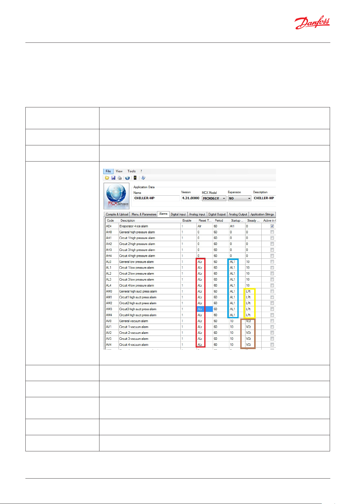
Pressure alarms from analogue input......................................33
Parameter: AHE, AHS, AHd, Alr, AL1, AL2, ALE, ALS, ALd, LPt,
AVO, VCt, SHS, SHb
High water temperature alarm in cooling mode.....................34
Parameter: Ats, Atd
Boiler water temperature alarm ...............................................34
Parameter: AbS, Abd
Fault of the regulation probe of the external coil ...................35
Parameter: ACM, ACS, ACd
Preventions ................................................................................35
Parameter: TMx, THo, TLo, HPE, HPo, HPh, LPE, LPo, LPh, PPt,
PPp, HFo
Superheat alarms ......................................................................37
Parameter: SHh, AHI, Ahi, AHd
Oil temperature alarms .............................................................37
Parameter: OTm, OTi, OTd
Screw compressors ....................................................................38
Parameter: C01, C02, CSO, CSb, T1, T2,T3, T4, C07, C08, T5, T6,
T21, T22, T24, T24, T25, T26, T27, T28, T29
Starting type of the compressor ..............................................42
Parameter: Sty, Sti, SSt, Stm, Sdd
Economizer ................................................................................43
Parameter: E01, EO2, EO3, EO4
Liquid injection ..........................................................................44
Parameter: T41, T42, T43, T44, T45
Compressor with unloaders ......................................................44
Parameter: C04, C05, C06, C08
Maximum number of compressor starts per hour ..................45
Parameter: CT0, CT1, CT2, CT3, CT4, CT5, CT6, CT7
Valve in the liquid line ...............................................................46
Parameter: Pd1, Pd2, Pd3, Pd4
Maximum compressor running hours .....................................47
Parameter: C50
Inverter compressor ..................................................................48
Parameter: IV0, IV1, IV2, IV3, IV4, IV5
Compressor enabling ................................................................50
Parameter: CT1, CT2, CT3, CT4, CT5, CT6, CT7, CT8
Heaters .......................................................................................50
Parameter: HE1, HE2, HE3, HE4, HE5, HE6, HE7
Pump of the internal coil ...........................................................51
Parameter: P01, P02, P03, P04
Modulating Pump ......................................................................52
Parameter: ERT, ECS, ECd, ECi, EHS, EHd, EHi, EDB, EI1, EI2, EI3
Fan for the internal coil .............................................................53
Parameter: P21, P22, P50
Free cooling ................................................................................54
Parameter: FrA, Fr1, Fr2, Fr3, Fr4, Fr5, Fr6, Fr7, Fr8, Fr9, FI1,
FI2, FI3
Valve in the water line ...............................................................56
Parameter: EF1, EF2
External coil ...............................................................................56
Parameter: F01
Fan requests ...............................................................................57
Parameter: F02, F03, FC, FCD, FCI, FCd, FHS, FHD, FHI, FHd
Fan regulation with a variable proportional part ...................59
Parameter: F31, F32, F33, F34, F35, F36, F37, F24, F25
2 | BC295150867120en-000201 © Danfoss | DCS (vt) | 2019.08
Page 3

User Guide | Chiller and reversable chiller, reciprocating, scroll and screw compressors
Economic setpoint for fan regulation ......................................60
Parameter: SS1, SS2, SS3, SS4
Stepless regulation of the fan ..................................................60
Parameter: F10, F11, F12, F13, F14, F20, F21, F22, F23
Hot gas bypass valve .................................................................61
Parameter: Bp0, Bp1
Cooling towers ...........................................................................62
Parameter: WFs, WFd
Reversing cycle valve (4 ways valve) ........................................63
Parameter: rE2, rE1, rE3, rE4
Defrost ........................................................................................64
Parameter: d01, d02, d03, d04, d05, d06, d07, d09, d10, d11,
d12, d13, d14, d15, d16, d20, d22, d23, d25, d26
Heat recovery .............................................................................66
Parameter: HRs, HRm, HRc, HRn, HRt, HRo
Superheat ...................................................................................67
Parameter: V10, V20, bAt, ex1, ex2, ex3, N19, N04, N05, N20,
N22, N10, N09, N11, N32, N18, N17, N15, N21, SHO
Input output expansion module ..............................................69
Parameter: XCn
Auxiliary alarms .........................................................................69
Parameter: a11, a21, a31, a41, a12, a22, a32, a42, a13, a23,
a33, a43, a 14, a24, a34, a44
Oil Alarm Tandem .....................................................................70
Parameter: BME, BST, TD1, TD2, TD3, TD4, ADO, BOF, BFR
Compressor Oil Pump................................................................72
Parameter: OPE, OPO, OT1, OT2
Temperature delta of the oil .....................................................73
Parameter: OTD, OD1, OD2
How to set the power request remotely ..................................73
Parameter: RPE, RPS
How to log data on an SD card .................................................74
Parameter: ENL
Commissioning ..........................................................................77
Parameter: Ort
Graphic diagrams of some of the managed unit types ..........80
Status variables .........................................................................91
Software status ..........................................................................91
Parameter: A01, …, A19, C01, …, C04, E01, …, E08
Software info .............................................................................92
Parameter: F01, …, F07
Superheat info ...........................................................................93
Parameter: H01, …, H13
Preparatory: link to MCXShape manual
© Danfoss | DCS (vt) | 2019.08 BC295150867120en-000201 | 3
Page 4
User Guide | Chiller and reversable chiller, reciprocating, scroll and screw compressors
User Interface
LED Display, LCD Display, Keyboard, Unit status, Login, Start,
Parameter, Input/Output, I/O Display, I/O Config, I/O Prb
Calibration, I/O Commissioning, Alarm, EEV, VSH Monitor, VSH
Control, Clock, Language, Service, Hours Counters, Variable
speed pump
Functionalities: Enable screen saver for LCD
Functionalities: Enable LED display
Enable support for MMILDS
Functionalities: Enable schema view
Functionalities: Enable I/O probe calibration
Functionalities: Enable override of input and output
Functionalities: Enable commissioning form
Functionalities: Enable EEV using EKE 1C
Enable MMI navigation
Functionalities: Enable EEV using EXD 316
Functionalities: Enable EEV using MCX driver
Functionalities: Enable VSH Modbus control
Functionalities: Enable Scheduler
Functionalities: Enable Evaporator variable capacity pump
Note: playing with MCXShape, it is very easy to customize the
structure and the visibility of the menu: so the following indication
cannot match with all the compiled software
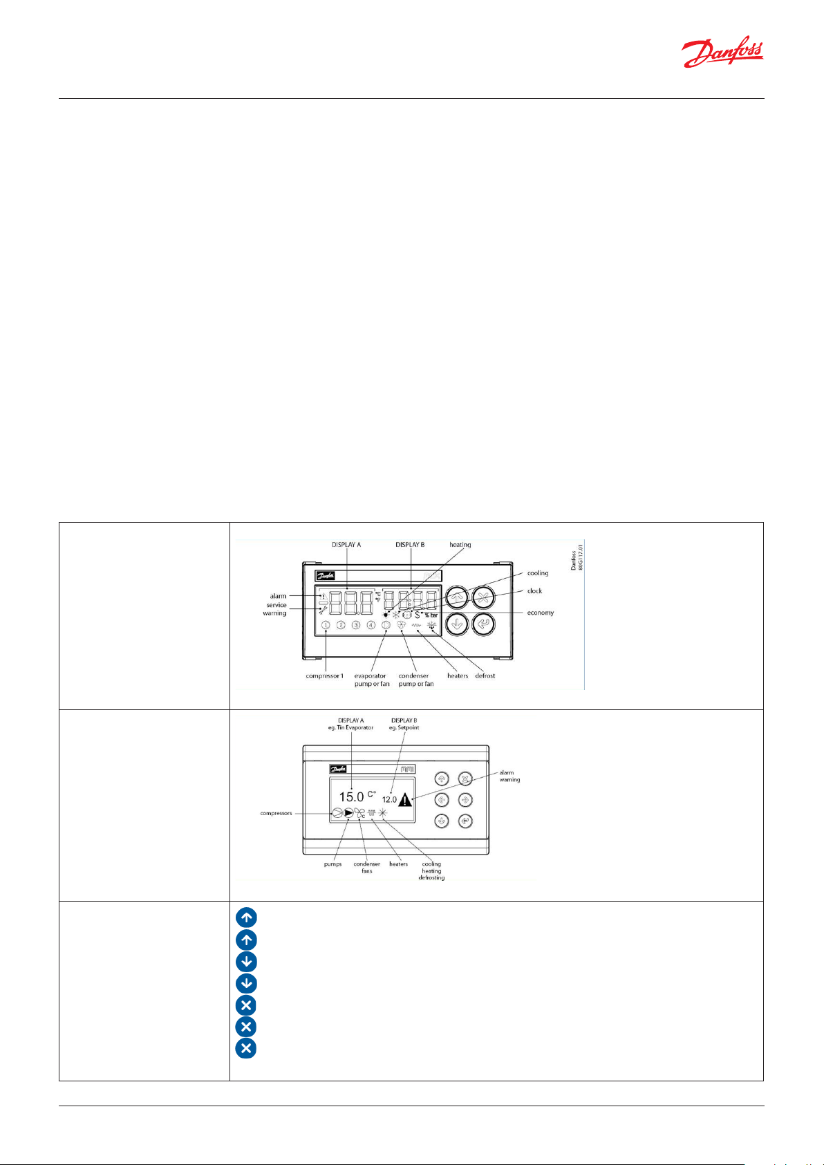
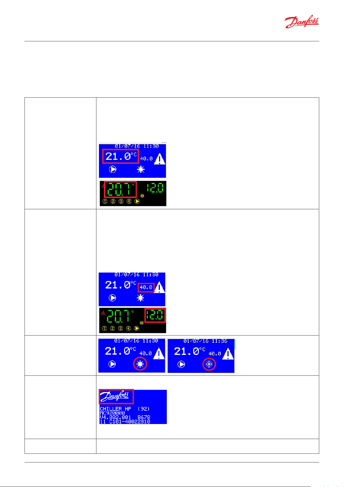
Main screen: LED Display Functionalities: Enable LED display
Note: check parameters dsA, dSb and dSC.
Main screen: LCD Display
Note: check parameters dsA, dSb and dSC.
Keyboard
: Scroll UP, increment a value
: 3s when in main screen: toggle ON/OFF
: Scroll down, decrement a value
: 3s when in main screen: toggle Heat/Cool mode
: exit and save,
: when in main screen: access the active alarm list
: 3s when in Alarm screen: manual reset
The LEFT and RIGHT keys, if present, allow you to move the cursor to the desired option
4 | BC295150867120en-000201 © Danfoss | DCS (vt) | 2019.08
Page 5
User Guide | Chiller and reversable chiller, reciprocating, scroll and screw compressors
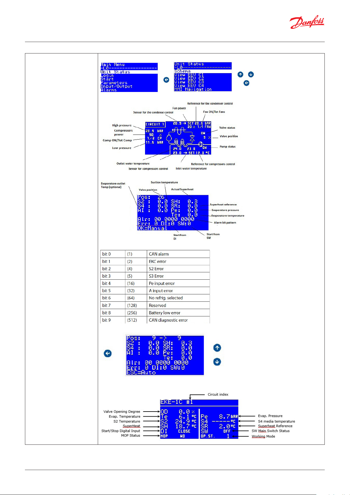
Menu: Unit Status Functionalities: Enable schema view
Schema:
View EEV Cx (for valve which is driven by EXD or MCX):
The alarms bit pattern is:
Note: by pressing “OK” key you manually tune the position of the valve
View EEV Cx (for valve which is driven by EKE):
© Danfoss | DCS (vt) | 2019.08 BC295150867120en-000201 | 5
Page 6
User Guide | Chiller and reversable chiller, reciprocating, scroll and screw compressors
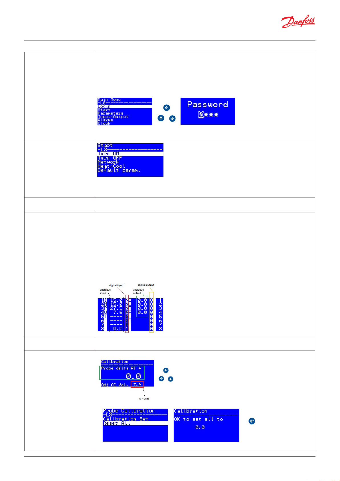
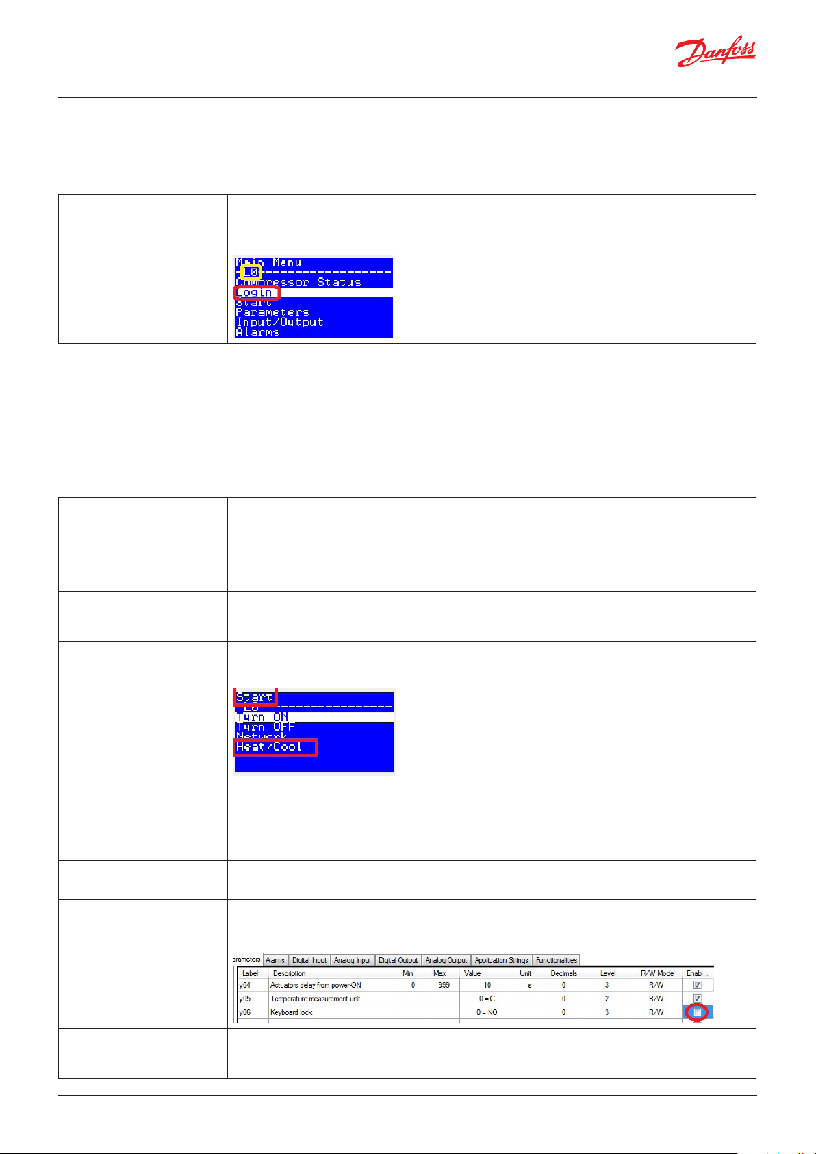
Menu: Login Parameters and Menu are organized into 4 access levels. Levels from 1 to 3 are linked to a password.
Elements cannot be accessed when they are on a higher level than the entering level. The level of
each parameter and menu is defined with MCXShape
• Level 0 is accessible without password
• Levels 1-3 are linked to a password (Check parameters L01, L02 and L03)
• Level 4 is not linked to a password, it can be used to make menu or parameters never reachable.
You can log in from the menu:
if the password provided is not correct you remain on the login screen. Otherwise you get back to
the main menu.
Menu: Start
Network menu: used to switch all the machines on or off in the Master and Slave network
Default param. menu: used to load the default value of the parameters which have been defined in
the .mcxs file
Menu: Parameter This menu contains all the parameters.
The meanings of the parameters are explained in the last part of this manual
Menu: I/O Display Display input and output values
LED display
Shows you (using the UP and DOWN keys) all the input and output values in sequence, showing the
I/O code on display A (“AI” for analogue input; “AO” for analogue output; “dI” for digital input and “dO”
for digital output) and its value on display B (analogue inputs that are not present or in alarm are
shown with “----”).
LCD display
You have access to three screens showing all the input and output values; each screen shows a group
of 8 I/O. Use UP and DOWN keys to scroll. The second and third screens are used with MCX15 and
MCX20 only.
The example below shows the first screen.
Menu: I/O Config This menu is prepared for future use
Note: it is under the 4th level of password
Menu: I/O Prb Calibration Functionalities: Enable I/O probe calibration
inside the “Reset All” menu, you can reset all the offsets to zero
Note: the screens calibration are not translated
6 | BC295150867120en-000201 © Danfoss | DCS (vt) | 2019.08
Page 7

User Guide | Chiller and reversable chiller, reciprocating, scroll and screw compressors
Menu: I/O Commissioning Functionalities: Enable override of input and output
Functionalities: Enable commissioning form
Note: the logic will not affect the override. The override is stopped for power off, "Reset all" command
and timeout that is defined into the menu "Setup"
Menu: Alarm Each alarm is described through an alarm description (for LCD display only), an alarm code and the
time since its activated in the format hours:minutes:seconds (seconds for LCD display only).
Note: You can also access alarm visualization by pressing the ESC key from the main screen.
The alarm is only reset if the alarm has ended and it will send you back to the main screen.
Note: Alarms can also be reset by holding ESC for 3 seconds on the alarm screens
Menu: EEV Functionalities: Enable EEV using EKE 1C
Functionalities: Enable EEV using EXD 316
The parameters inside the external drivers can be checked and changed in the Config EEVx menu.
The available parameters for the EXD are: r05, r09, r10, r12, A34, n04, n05, n06, n09, n10, n11, n15,
n17, n18, n19, n20, n21, n22, n32, n37, n38, n39, n40, n42, n43, n44, n45, n50, o10, o18, o20, o21,
o30, o45, o56, o61, n03
The available parameters for the EKE are: R012, R009, r105, r107, O030, N102, N015, N104, N017,
N021, N107, N009, N010, N116, N005, N019, N004, N020, N117, N119, N130, N011, N140, N141,
A034, A103, A104, A110, A102, I020, I022, I040, I042, I043, O020, O021, I067, R005, B101, O002,
O022, G003, N108, N109
The Load Factory menu overwrite the EXD parameters with the default ones
© Danfoss | DCS (vt) | 2019.08 BC295150867120en-000201 | 7
Page 8

User Guide | Chiller and reversable chiller, reciprocating, scroll and screw compressors
Menu: VSH Monitor Functionalities: Enable VSH Modbus control
VSH Status:
VSH Alarms:
The STW bit-map is:
VSH inverter details:
8 | BC295150867120en-000201 © Danfoss | DCS (vt) | 2019.08
Page 9
User Guide | Chiller and reversable chiller, reciprocating, scroll and screw compressors
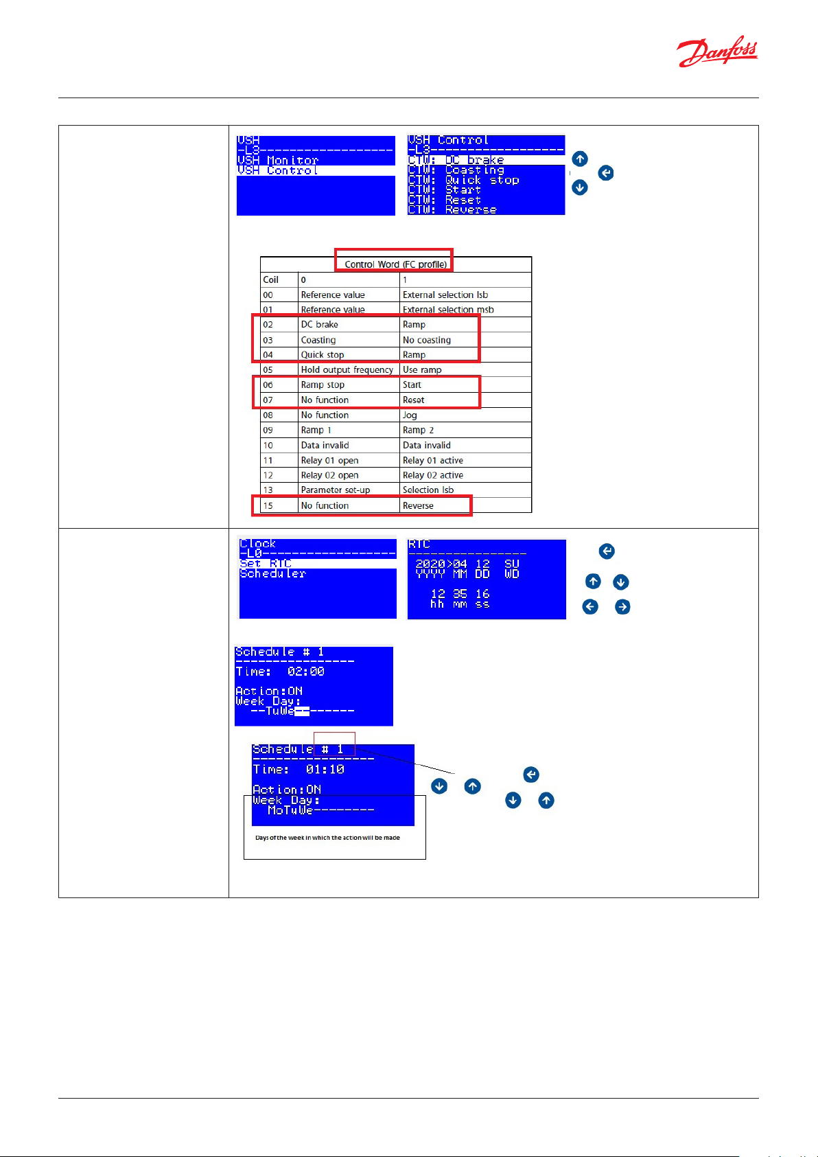
Menu: VSH Control
These commands are linked with the control word of the inverter
Menu: Clock
Functionalities: Enable Scheduler
Note: with the number beside to the function "Enable scheduler" you set the maximum amount of
records, before to change it consider that it also affects the EEPROM.
© Danfoss | DCS (vt) | 2019.08 BC295150867120en-000201 | 9
Page 10
User Guide | Chiller and reversable chiller, reciprocating, scroll and screw compressors
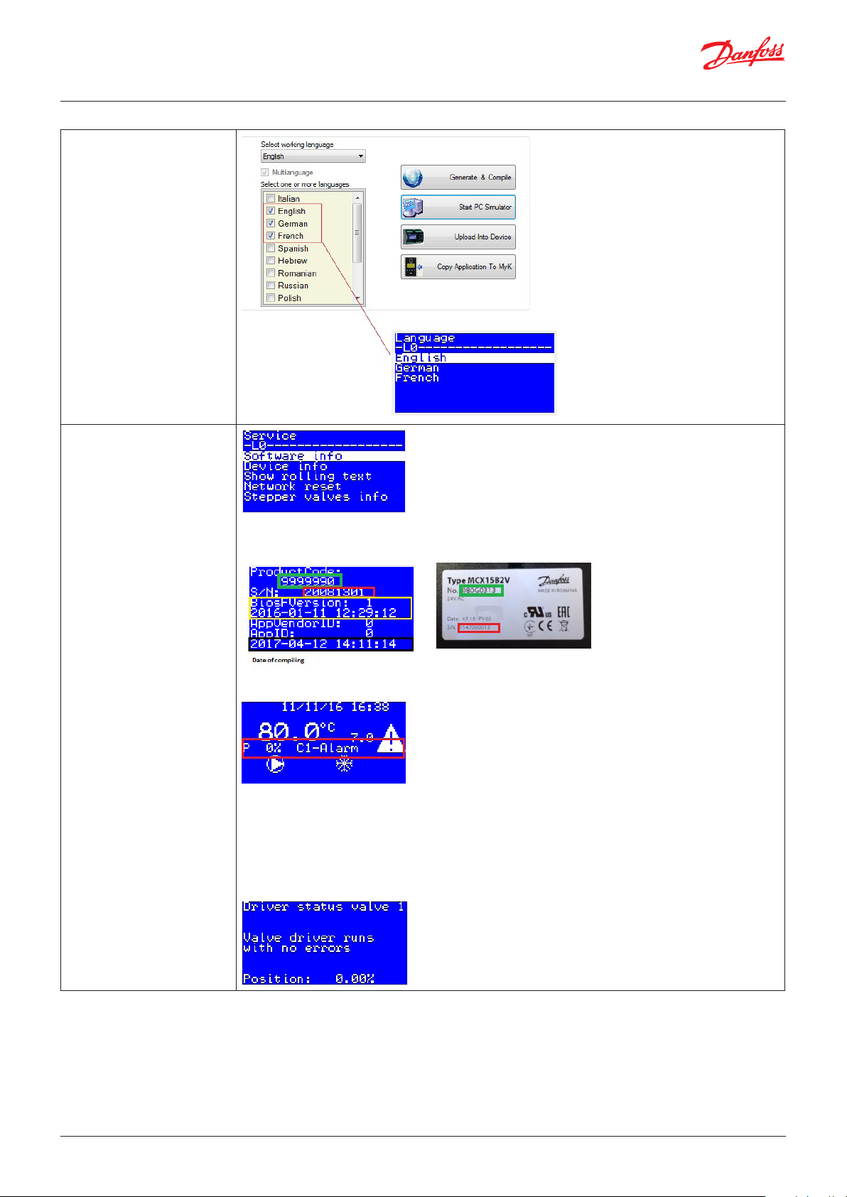
Menu: Language
Menu: Service
Software info: Check variables status F01-F07
Device info:
Show rolling text:
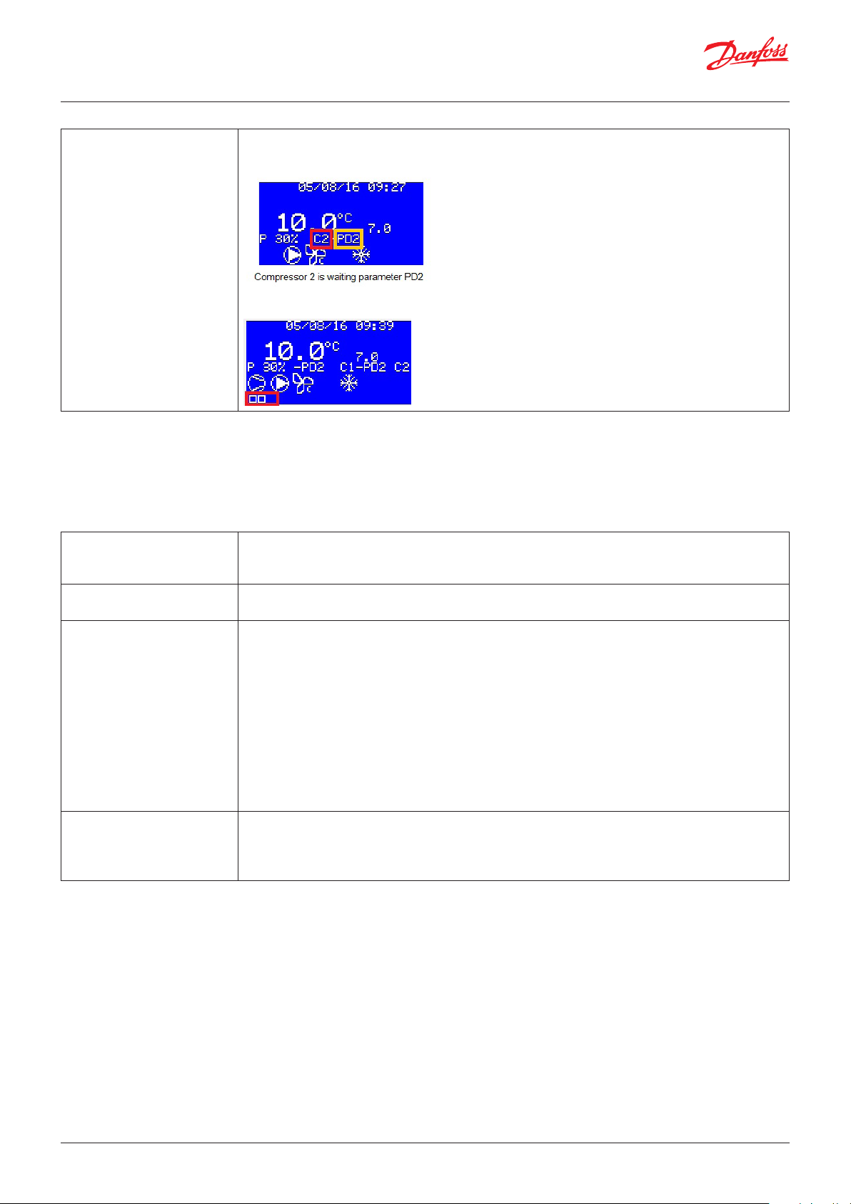
Enabling rolling text will add additional information in the main screen
- P: Power demand
- Cx- Alarm: Compressor X is in alarm
- Cx- CTy: Compressor X is waiting for the parameter with the label CTy
- P-Down: Compressor is waiting for pump down to be switched off
- Cx- Prev: Circuit X is being reducing by prevention
Network reset: it restarts from zero the managing of the master slave network
Stepper valves info:
10 | BC295150867120en-000201 © Danfoss | DCS (vt) | 2019.08
Page 11

User Guide | Chiller and reversable chiller, reciprocating, scroll and screw compressors
Menu: Hours Counters Note: The Reset Counters menu resets to zero all the counters, compressors and both pumps.
For resetting the single compressor or pump push "Enter" button into the screen where are reported
the hours of the device.
© Danfoss | DCS (vt) | 2019.08 BC295150867120en-000201 | 11
Page 12
User Guide | Chiller and reversable chiller, reciprocating, scroll and screw compressors
Parameters
Display
Parameter: dSA, dSb, dsc, Log, Par
How to customize the main screen.
dSA-Display A value 0= OFF : Display A is not used
1= IdOF : Display A shows the state of the digital input ON/OFF
2 =SEt : Display A shows the set point of the compressors regulation
3 =rEg : Display A shows the probe used for regulation
4=AI1 : Display A shows the value of the analogue input 1
……
19 =AI16 : Display A shows the value of the analogue input 16
dSb-Display B value 0 =OFF : Display B is not used
1=IdOF : Display B shows the state of the digital input ON/OFF
2=SEt : Display B shows the set point of the compressors regulation
3 =rEg : Display B shows the probe used for regulation
4 =AI1 : Display B shows the value of the analogue input 1
…
19 =AI16 : Display B shows the value of the analogue input 16
20 =TcP1 : Display B shows the temperature calculated from the dP1 sensor
…
23 =TcP4 : Display B shows the temperature calculated from the dP4 sensor
dsc-Icone for cooling mode
Log- Logo Log=0 is combined with the image StartLogoDX in Chiller/BIN/Graph folder
Log=1 is combined with the image StartLogoDX_1 in Chiller/BIN/Graph folder
Note: the logo is shown just after the power on, pay attention to the size of the image because it is fit
in this screen
Par- Parameters version It is not used in the software, can be used to recognize different set of parameters
Note: this number is reported into the software information
12 | BC295150867120en-000201 © Danfoss | DCS (vt) | 2019.08
Page 13
User Guide | Chiller and reversable chiller, reciprocating, scroll and screw compressors
Password
Parameter: L01, L02, L03
How to change the passwords.
L01, L02, L03-
Level x password
Typing the parameter L0X, in the login screen, you will be able to see all the parameters and menu
with level <= of X;
The level of access is highlighted in the yellow square;
after 10 minutes of inactivity the display is set to an access level of zero
SetUp
Parameter: y01, y02, y03, y04, y05, y06, y08, y09
How to switch ON-OFF and change the application mode from parameters.
Functionalities: Enable scheduler
Functionalities: Enable show compressor status
Digital input: ONO
Digital output: UNT
y01- System ON/OFF 0=Machine OFF
1=Machine status depends on the DI _ONO
Defines whether the chiller is in the ON or OFF state, it can be changed from the menu, remotely by
Modbus or CANBUS and from start screen by holding the up arrow key.
Note1: The software is in ON status only if y02=ON and DI_ONO=ON
Note2: The chiller status is also reported in the digital output UNT_Unit Status
y02- Restart mode after
power OFF
y03- System heat/cool It works only with H40> 0 and rE2=UI;
0=OFF means that after power on, the chiller gets up in OFF state
1=ON means that after power on, the chiller gets up in ON state
2=EQUA means that after power on, the chiller keeps the same state as before power off
This defines whether the machine should be in chiller mode or heat pump mode.
This parameter can also be changed from the “Start” menu
y04- Actuators delay from
power ON
y05- Temperature
measurement unit
y06- Keyboard lock 0=No
y08- Scheduler enable 0=No means that the scheduler is disabled
© Danfoss | DCS (vt) | 2019.08 BC295150867120en-000201 | 13
It is in seconds and sets the delay when powered ON (not when the unit status changes to ON) before
activating any outputs. Its purpose is to distribute the drawn current and protect the elements and
particularly the compressor against repeated starts in the event of frequent power failures. When the
timer has elapsed, the controller starts to manage the outputs based on the other times and the other
normal functions.
0=C means that the user interface will show values in Celsius and bar
1=F means that the user interface will show values in Fahrenheit and PSI
1=Yes means that the user interface is locked
Note: This parameter can be adjusted in order to be set remotely because it is not enabled for the menu
1=Yes means that the scheduler is enabled
Note: the “Enable scheduler” functionality is required
Page 14
User Guide | Chiller and reversable chiller, reciprocating, scroll and screw compressors
y09- Show rolling test 0=No
1=Yes
Provides information about what is going on in relation to the cutting in/out of the compressors
Note: If the functionalities “Enable show compressor status” is enabled in the UI, a small icon is
added for each compressor
Serial setting
Parameter: Cid, Ser, bAU, COM
How to configure the communication port.
Functionalities: Enable Modbus address different from CANBUS address
Cid – Serial address (CAN) Defines the ID in the CANBUS communication
Note: the baud rate and the settings of the CANBUS communication is tuned through the bios menu
or though the MYK
SEr – Serial address (MODBUS) Defines the ID in the Modbus communication
Note: the functionalities “Enable Modbus address different from CANBUS address” is required
bAU – Serial baud rate (Modbus)
COM – Serial settings
(Modbus)
Defines the baud rate in the Modbus communication
0 means Reserved: do not use
1 means 1200 bits/sec
2 means 4200 bits/sec
3 means 4800 bits/sec
4 means 9600 bits/sec
5 means 14400 bits/sec
6 means 19200 bits/sec
5 means 28800 bits/sec
8 means 38400 bits/sec
9 means 57600 bits/sec
8 means 115200 bits/sec
Defines the serial settings of the Modbus communication
0 means 8N1
1 means 8E2
2 means 8N2
14 | BC295150867120en-000201 © Danfoss | DCS (vt) | 2019.08
Page 15

User Guide | Chiller and reversable chiller, reciprocating, scroll and screw compressors
Evaporator
Parameter: H1, H2, H3, H4, H5, H12
How to configure the internal coils.
Digital input: OPE, OPE1, OPE2
Digital output: PE1, PE2, …, PE8, H1, …, H4
Analogue input: TIN, TOM, TO1, …, TO4
Analogue output: E1, …, E4
Alarms: AE1, AO7, AP0, AP1, …, AP9
H1 – Number of evaporators Defines the number of internal coils;
The supply temperature (TIN) is the same for all the coils.
Each coil has a “leaving temperature” (T01-T04) ; there is also a common “leaving temperature” sensor
for all the coils ( TOM)
H2 – Number of circuits per
evaporator
H3 – Air or water cooling Defines whether the evaporation process is managed by a pump (H3=H2O) or a fan (H3=Air):
H4 – Number of pump/fan per
evaporator
H5 – Number of heaters per
evaporator
H12 –Fan in common for each
evaporator
Defines the number of circuits for each internal coil;
Configuration accepted:
• 1 circuit per internal coil -> 0<H1<5
• 2 circuits per internal coil ->0<H1<3
• 3 circuits per internal coil H1=1
• 4 circuits per internal coil H1=1
• WATER evaporators (H3=H2O). For each evaporator, the H1,...,H4 digital outputs which are
necessary to manage the antifreeze heaters on the basis of the leaving water temperature TO1,...,TO4
are controlled. The number of heaters per evaporator is defined by H5.
• AIR evaporators (H3=Air). Only the “TO1_Tout Evaporator 1” input is used to measure the supply air
temperature even when more than one evaporator is present. The ice alarm AE1 is replaced with the
Low air temperature warning A07 which is set to the same parameters as the ice alarm.
Defines the pumps (or fan) per evaporator:
• WATER evaporators (H3=H2O): The PE1 and PE2 digital outputs are managed to control one pump
or two twin pumps.
• AIR evaporators (H3=Air): “PE1 and PE2” outputs are used to manage fans on the evaporator.
Note: check "Fun for internal coil"
Defines the number of heaters for each internal coil;
Configuration accepted:
• 1 heater per internal coil -> 0<H1<5
• 2 heaters per internal coil ->0<H1<3
• 3 heaters per internal coil ->H1=1
• 4 heaters per internal coil ->H1=1
0=NO means that each fan (AO ECx) works in relation to the evaporator pressure
1=Yes means that only the fan EC1 will work in relation to worst pressure in the evaporators
Note: the fan speed is managed with PI logic (check parameters ECS,….,Hi)
© Danfoss | DCS (vt) | 2019.08 BC295150867120en-000201 | 15
Page 16

User Guide | Chiller and reversable chiller, reciprocating, scroll and screw compressors
Compressor
Parameter: H6, H7
How to configure the compressors number.
H6 – Number of compressor
per circuit
H7 – Number of unloader per
compressor
Defines the number of compressor per circuit;
It’s not possible have circuits with different number of compressors
Configuration accepted:
• 1 compressor per circuit -> 0<H1*H2<5
• 2 compressors per circuit ->0<H1*H2<5
• 3 compressors per circuit ->0<H1*H2<3
• 4 compressors per circuit ->0<H1*H2<3
• >4 compressors per circuit ->0<H1*H2<2
Defines the number of compressor partialisation;
The number of regulation steps is equal to H6*H2*H1*(H7+1)
Activation and deactivation of the compressor’s unloader is defined by the parameters
“C04-Unloaders activation mode” and “ C05-Unloaders deactivation mode”
16 | BC295150867120en-000201 © Danfoss | DCS (vt) | 2019.08
Page 17

User Guide | Chiller and reversable chiller, reciprocating, scroll and screw compressors
Condenser
Parameter: H9, H10, H11
How to configure the external coil.
Digital input: OFC, FCL1, …, FCL4, OFC1, …, OFC12
Digital output: FC1, …, FC12
Analogue output: Fc1, …, Fc4
Alarm: AF1, …, AF12
H9 – Air or water cooler
condenser
H10 – Number of pump/fans
per condenser
H11 –Fan in common to all
condenser
Defines whether the fans or the pump regulate condensing.
0=AIR : Controls defrosting in heating mode.
1=HO : The configuration managed is H10=1 and H11=Yes
Note: the pump or fan behaviour is defined by parameters F01, F02 and F03
Defines the necessary digital output to control the pumps or fans on the condenser.
• Water-cooled units (H9=H2O).The single “Cond Fan1/Pump1” digital output is controlled to drive
a pump.
• Air-cooled units (H9=AIR). Contributes to defining the total number of managed ventilation steps and
thus of the corresponding ”Condenser Fan1”, ..., ”Condenser Fan8” digital outputs used to drive them.
On multi-circuits units, fans can be in common to all condensers.
If fans are not in common to all condensers (H11=0=NO), the following output are controlled:
• as many analogue inputs as the condensers (H1*H2)
• as many digital outputs as the condensers (H1*H2), multiplied by the number of fans per condenser
(H10); digital outputs for fans are assigned to condensers in a sequential and balanced way,
assuming that all condensers have the same number of fans; e.g. in a system made of 2 condensers
and 6 fans, “Cond Fan1/Pump1”, “Condenser Fan2” and “Condenser Fan3” outputs are assigned to
control fans belonging to the first condenser; “Condenser Fan4”, “Condenser Fan5” and “Condenser
Fan6” to the second condenser.
• as many analogue output s “InverterFanCond1”,...,”InverterFanCond4” for condensing control as for
the condensers (H1*H2).
If fans are common to all condensers (H11=1=YES) the following outputs are used:
• as before, as many analogue inputs for condensing controls as there are circuits per condenser
(H1*H2), but the one requiring the higher response from the control is used for regulation. Each
analogue input is then used for defrost control in heating mode;
• as many digital outputs as fans per condenser (H10);
• one analogue output “InverterFanCond1” for fan speed regulation.
© Danfoss | DCS (vt) | 2019.08 BC295150867120en-000201 | 17
Page 18
User Guide | Chiller and reversable chiller, reciprocating, scroll and screw compressors
Heat Pump
Parameter: H40, H41, H42
How to configure the heat pump mode
Functionalities: Enable Heat Pump Control
Digital output: HC1, …, HC4, BO1, …, BO4
Analogue input: SP1, …, SP4, dP1, …, dP4
H40 –Heat pump type 0=No means that the software does not perform heating mode
1=GAS means that the software performs the heating mode, the internal coil is the evaporator in
cooling mode and the condenser in heating mode
1=H2O means that the software performs the heating mode, the coils keep the same meaning in
both heating and cooling mode both
Note: one digital output “Reverse Valve C1”, ..., “Reverse Valve C4” per each circuit is reserved for
controlling the reverse flow valve
H41- Boiler number of heaters Boiler heaters “Boiler1”, ..., “Boiler4” are turned ON when the temperature measured by the regulation
probe enters in the area defined by the active regulation setpoint in heating (SH1) and differential rH1.
They are an alternative to the heat pump, not in addition.
Boiler heaters can be activated only if the temperature measured by the “BoilerSafety” probe is
under a specific safety limit AbS. If it is over the limit, alarm A14 is generated.
To reset the alarm there is a constant differential Abd to be considered.
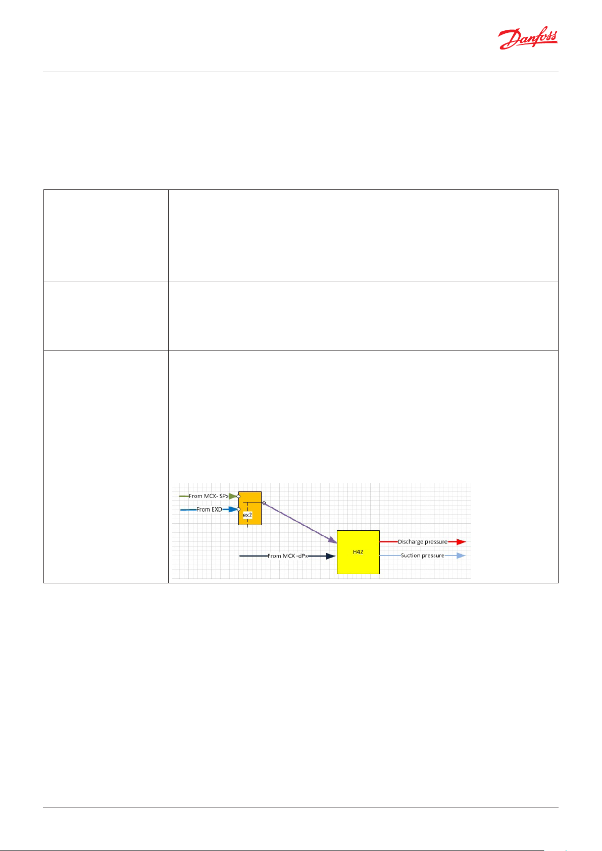
H42- Probe change in HP 0=No means that the probe is before the 4-way valve (close to the compressor):
• the sensor SPx – Suction pressure Cx measures low pressure
• the sensor dPx – Discharge pressure Cx measures high pressure
1=Yes means that the probe is after the 4-way valve (close to the coils):
• the sensor SPx – Suction pressure Cx measures low pressure in cooling mode and high pressure in
heating mode
• the sensor dPx – Discharge pressure Cx measures high pressure in cooling mode and low pressure
in heating mode
Note: if ex2=yes the variable used from H42 (pink line below) is always about low pressure, in
this case pay attention to set H42=No because in heating mode the discharge pressure will not
be available
18 | BC295150867120en-000201 © Danfoss | DCS (vt) | 2019.08
Page 19

User Guide | Chiller and reversable chiller, reciprocating, scroll and screw compressors
Maintenance
Parameter: H43
How to manually set the compressor power request.
Functionalities: Enable commissioning for power request
Digital output: MPR
H43- Manual chiller power The power request provided to the compressors is about H43 %
H43< zero means that the function is disabled
Note: if H43 >=0 the digital output MPR is closed
© Danfoss | DCS (vt) | 2019.08 BC295150867120en-000201 | 19
Page 20
User Guide | Chiller and reversable chiller, reciprocating, scroll and screw compressors
Network settings
Parameter: n01,…n17
The Master and Slave is a functionality that allow a group of machines to be
managed like one machine (Master) decides which and how many units (Slaves)
should run.
The max number of units is 8 (7 slaves + 1 master), the network is CANBUS.
The Master and Slave function optimizes:
- ageing of machines
- distribution of the load in order to improve the performance of the plant
- The backup units
Functionalities: Enable Master/Slave
Alarms: N01, N02, N03, N04, N05,N06, N07, N08
n01 –MCX network disable 0=NO means that the Master slave function is enabled
1=Yes means that the Master slave function is disabled
n02 –Number of slave nodes It has to be set equal to (“number of chillers in the network” -1)
n03- Auto master select 0=NO means that the master in the master slave network can be only the chiller with the CANBUS ID
equal to n15: if the master is not more available in the network, the other chillers will start to work in
standalone mode
1=Yes means that the master in the master slave network is the chiller with lowest CANBUS ID
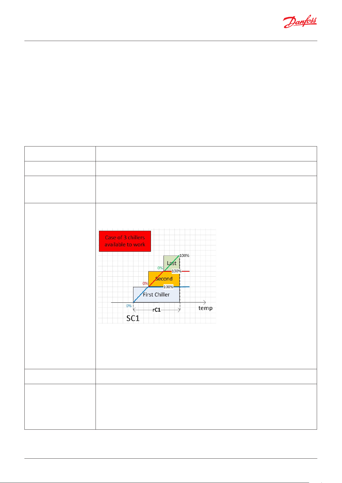
n04- Distribution algo 0= PWR The master, using its own sensors, decides how many chillers are working and the chillers’
power supply;
The maximum number of units that can work is related to the gap between setpoint and
temperature: practically the regulation band is divided for the number of machines (n02+1-n09):
1= CAP the master manages only the start order (following the ageing of the machines), chillers
manage their power as standalone machines.
If all the units which are running have capacity above n12 %, the master will switch on another chiller (the
youngest one).
If all the units which are running have capacity below n13 %, the master will switch off the oldest chiller
running
The minimum time between two actions of the master is n14 seconds
n05- Power Smart power
distribution enable
n06- Node rotation enable 0=No means that the start sequence of the machines is fixed; the order depends on the addressing,
20 | BC295150867120en-000201 © Danfoss | DCS (vt) | 2019.08
1=Yes means that the master is allowed to cut-in the first chiller available without considering the
start order related to the ageing of the machines
the first to start is the machine with the smallest CANBUS ID, the first to stop is the chiller with the
highest CANBUS ID
1=Yes means that the start/stop sequence of the machines depends on the ageing of the chillers,
always starting with the youngest of the set and the oldest one is always the first to stop. In the case
that one machine works n17 hours more than another chiller that is switched off, the master will
exchange the unit in order to align the ageing.
Page 21
User Guide | Chiller and reversable chiller, reciprocating, scroll and screw compressors
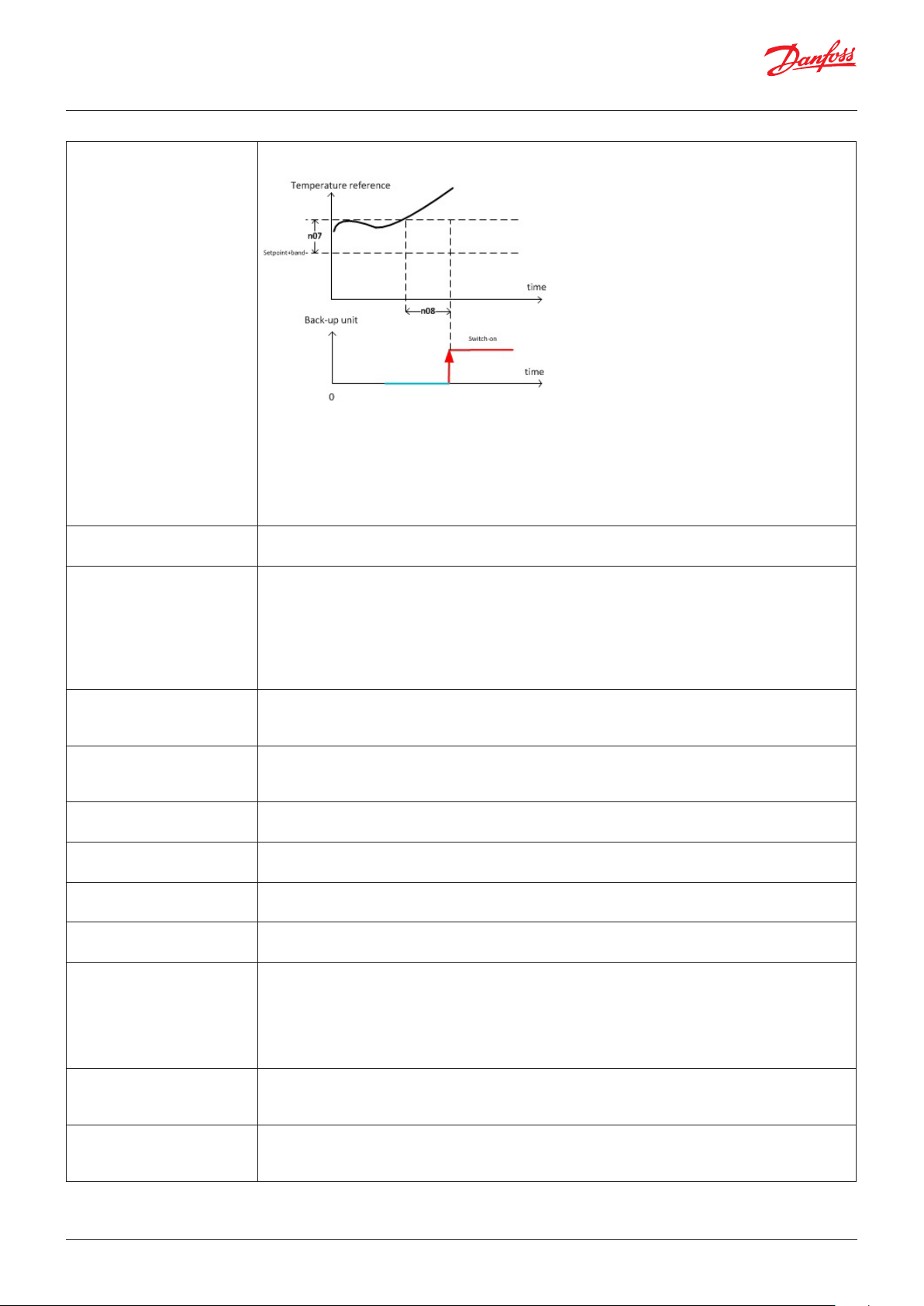
n07- Backup node offset When the gap between setpoint and temperature is above (n07+regulation band), the first backup
unit is allowed to work as a support, also considering parameter n08 .
Note: the offset to enable the other backup units is (n07*m+ regulation band):
• m = 2 for the second backup unit
• m = 3 for the third backup unit
• …
Note: the backup units will work running normally after the set point. It will be switched off when the
gap between setpoint and temperature is below the regulation band
Note: the pump behaviour is defined through the parameter P01
n08- Time to enable n07 It’s the time to stay far away from the setpoint in order to cut in the backup unit
Note: check parameter n07
n09-Number of back-up unit n09 defines the number of backup units inside the master slave network
A backup unit is never enabled (so does not provide cooling capacity) unless one of the following
situations occurs:
• one of the other units becomes unavailable
• Support (see parameter n07 and n08)
Note: The master chooses the backup unit (among all nodes present in the network) by looking at
the working time of every unit: the one which has worked the longest will be the backup unit.
n10 – Evaporator in common 0=No each chiller consider its own evaporator flow alarm
1=yes the master will read its “FPE” digital input (Flow Evaporator) and will send the information to
other slaves
n11 – Pump alarm in common 0=No each chiller considers its own pump alarm
1=yes the master will read its “AP1” digital input (Evap pump/fan overload alarm) and will send the
information to other slaves
n12 – Capacity upper
threshold
n13 – Capacity lower
threshold
n14 – Capacity step min time See parameter n04
See parameter n04
See parameter n04
n15 – Master node CAN ID It has to be set equal to the lowest ID in the CANBUS network
n16 – Slaves node CAN ID offset The slaves have to take the CAN ID in relation to the n15 just adding n16.
E.G. for n02 =3
• Master ID= n15
• Slave1 ID= n15+n16
• Slave2 ID= n15+n16+n16
• Slave3 ID= n15+n16+n16+n16
n17 – Maximum gap time for
unit rotation
n18 – Backup unit pump
status
© Danfoss | DCS (vt) | 2019.08 BC295150867120en-000201 | 21
It is in hours
If a running unit becomes older than a switched-off unit by more than n17 hours, the logic will
switch off the oldest unit running it will cause the other unit to be switched on.
0=OFF: the backup chillers in standby have the pump switched-off
1=ON: the backup chillers in standby have the pump switched-on
Note:during support or backup, the pump of the chiller follow P01 setting
Page 22

User Guide | Chiller and reversable chiller, reciprocating, scroll and screw compressors
Configuration
Parameter: rEG, rET, rT1, rT2, o30, Er1
rEG – Analogue input for
temperature regulation
rET – Regulation Type Defines the relation between the temperature gap and the power request to the circuits.
0= Tin : reference sensor is Tin_Tin Evaporator
1= ToM: reference sensor is TOM_Tout Evap Mix
2 =AI1: reference sensor is the analogue input 1
……
17 =AI16 : reference sensor is the analogue input 16
18 =SPT1: reference is the temperature calculated from the sensor SP1_Suction Press C1, the gas
type is set using parameter o31
0=P : Power request to the circuits increases in proportional way with the regulation error, i.e., it is
100% when the regulation error (the gap between setpoint and the reference sensor ) is equal to rC1
( rH1)
1=PI: the power request is the sum of P regulation (rET=0) plus a component (Integral part)
that increases in relation to the regulation error; the speed of the integral part depends on the
parameter rin_Ti.
For PI regulation, the balance is reached only when the regulation sensor gets the setpoint.
2=dZ : The delay between compressors activations varies between a maximum value dd5 and
minimum value dd6 proportional to the temperature position inside the regulation band defined by
the activation differential dd1.
Above setpoint + dead zone + activation differential, the delay among activations is equal to the minimum.
rT1- Minimum limit for
TReg TX
rT2- Maximum limit for
TReg TX
Similarly the action for the delay among compressors deactivations, which can vary between a
maximum value dd7 and a minimum value dd8, is proportional to the temperature position inside
the regulation band defined by the deactivation differential dd2.
Below a setpoint differential, the delay among activations is equal to the minimum value, dd8, up
to a limit threshold, dd3. Below that, all the compressors are immediately switched OFF to avoid the
unit ice alarm.
The analogue output rtr linearly replays the regulation probe (check parameter rET)
It gets to 0% when the regulation probe reaches a value of rT1
Note: if the regulation probe is in error the AO_rtr gets to 100%
The analogue output rtr linearly replays the regulation probe (check parameter rET)
It gets to 100% when the regulation probe reachs rT2 value
Note: if regulation probe is in error the the AO_rtr gets to 100%
22 | BC295150867120en-000201 © Danfoss | DCS (vt) | 2019.08
Page 23

User Guide | Chiller and reversable chiller, reciprocating, scroll and screw compressors
o30 – Gas type 0=---
1=R12
2=R22
3=R134a
4=R502
5=R717
6=R13
7=R131b1
8=R23
9=R500
10=R503
11=R114
12=R142b
13=-14=R32
15=R227
16=R401a
17=R507
18=R402a
19=R404a
20= R407c
21= R407a
22= R407b
23= R410a
24= R170
25= R290
26=R600
27= R600a
28= R744
29= R1270
30=R417a
31=R422a
32=R413A
33=R422D
34=R427A
35=R438A
36=R513A
37=R407F
38=R1234ze
39=R1234yf
40=R448A
41=R449A
42=R452A
43=R450A
44=R452B
45=R454B
46=R1233zdE
47=R1234zeZ
48=R449B
49=R407H
Note: the gas definition is used when the translation of the pressure in temperature is required;
ReG=SPT1 and for the “internal” super heat control
o31 – Dew/Bubble Conversion
mode
Er1 – Emergency mode
max power
0=Dew
1=Bubble used for the gas that require the "Glide" approximation
Er1 = -1 the function is disabled
Er1 >= 0 when the digital input EEr is closed the power request is limited to Er1 instead of 100%
Note: the functionality “Enable emergency mode from DI” is required
© Danfoss | DCS (vt) | 2019.08 BC295150867120en-000201 | 23
Page 24
User Guide | Chiller and reversable chiller, reciprocating, scroll and screw compressors
Main Setpoint
Parameter: SC1, SCL, SCH, SH1, SHL, SHH, SRE
Analogue input: TRM
SC1 – Cooling temperature set
point
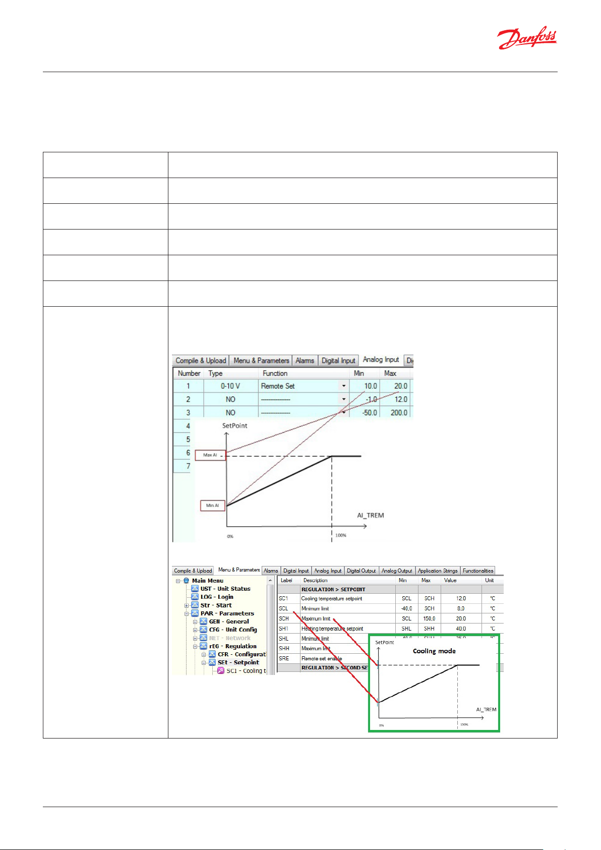
SCL – Minimum limit Defines the minimum limit of the setpoint in cooling mode
SCH – Maximum limit Defines the maximum limit of the setpoint in cooling mode
SH1 – heating temperature set
point
SHL – Minimum limit Defines the minimum limit of the setpoint in heating mode
SHH – Maximum limit Defines the maximum limit of the setpoint in heating mode
SRE- Remote set enable The regulation setpoint is defined through the analogue input TRM_Remote Set
Defines the setpoint in cooling mode
Note: This limit is not respected when adjusted through Modbus
Note: This limit is not respected when adjusted through Modbus
Defines the setpoint in heating mode
Note: This limit is not respected when adjusted through Modbus
Note: This limit is not respected when adjusted through Modbus
0=NO means that the function is not enabled
1=rEL means that
set point = main setpoint + offset from analogue input (TRM_Remote set)
2=Abs means that set point is linearly defined through AI_TREM, between SCL - SCH in cooling and
SHL - SHH in heating
24 | BC295150867120en-000201 © Danfoss | DCS (vt) | 2019.08
Page 25

User Guide | Chiller and reversable chiller, reciprocating, scroll and screw compressors
Economic Setpoint
Parameter: SdS, SdM, SdC, SdH, SdO
SdS- Setpoint selection 0=DI means that the digital input SET2_Reg offset from DI defines if use comfort setpoint (SC1 or
SH1) or the economic setpoint (SC1+SdC or SH1-SdH); in economic mode the proportional band in
the PI control is increased by SdO
1=PAR meaning that the parameter SdM_Setpoint mode defines whether comfort setpoint
(SC1 or SH1) or the economic setpoint (SC1+SdC or SH1-SdH) is to be used; in economic mode the
proportional band in the PI control is increased by SdO
SdM- Setpoint mode It works only for SdS=PAR
0=COMF meaning that chiller uses comfort setpoint ( SC1 or SH1)
1=ECO meaning that the chiller uses economic setpoint (SC1+SdC or SH1-SdH)
In economic mode the proportional band in the PI control is increased of SdO.
SdC-Offset for setpoint in cool-
ing
In economic status and cooling mode the regulation setpoint is shifted to SdC.
Note: see parameter SdS
SdH-Offset for setpoint
in heating
SdO-Offset for differential In economic mode the proportional band of regulation becomes rC1+SdO or rH1+SdO.
In economic status and heating mode the regulation setpoint is shifted to SdH.
Note: Take a look to parameter SdS
Note: look at parameter SdS
© Danfoss | DCS (vt) | 2019.08 BC295150867120en-000201 | 25
Page 26
User Guide | Chiller and reversable chiller, reciprocating, scroll and screw compressors
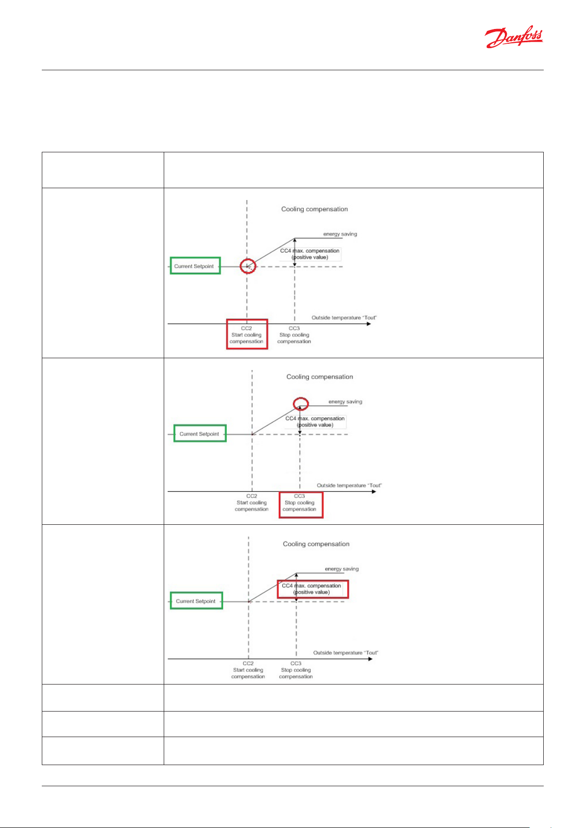
Setpoint compensation in based on the outside temperature
Parameter: CC1, CC2, CC3, CC4, CH2, CH3, CH4
Analogue input: OUt
CC1-Compensation enable 0=NO means compensation disable
1=YES means compensation enable
Note: this function adapts the setpoint to the outside temperature “Tout”
CC2-Outside temperature to
start cool comp.
It’s in °C
CC3-Outside temperature to
stop cool comp.
CC4-Maximum cooling
compensation
It’s in °C
It’s in °C
CH2-Outside temperature to
start heat comp.
CH3-Outside temperature to
stop heat comp.
CH4-Maximum heating
compensation.
26 | BC295150867120en-000201 © Danfoss | DCS (vt) | 2019.08
It’s in °C
Like CC2 but used in heating mode
It’s in °C
Like CC3 but used in heating mode
It’s in °C
Like CC4 but used in heating mode
Page 27
User Guide | Chiller and reversable chiller, reciprocating, scroll and screw compressors
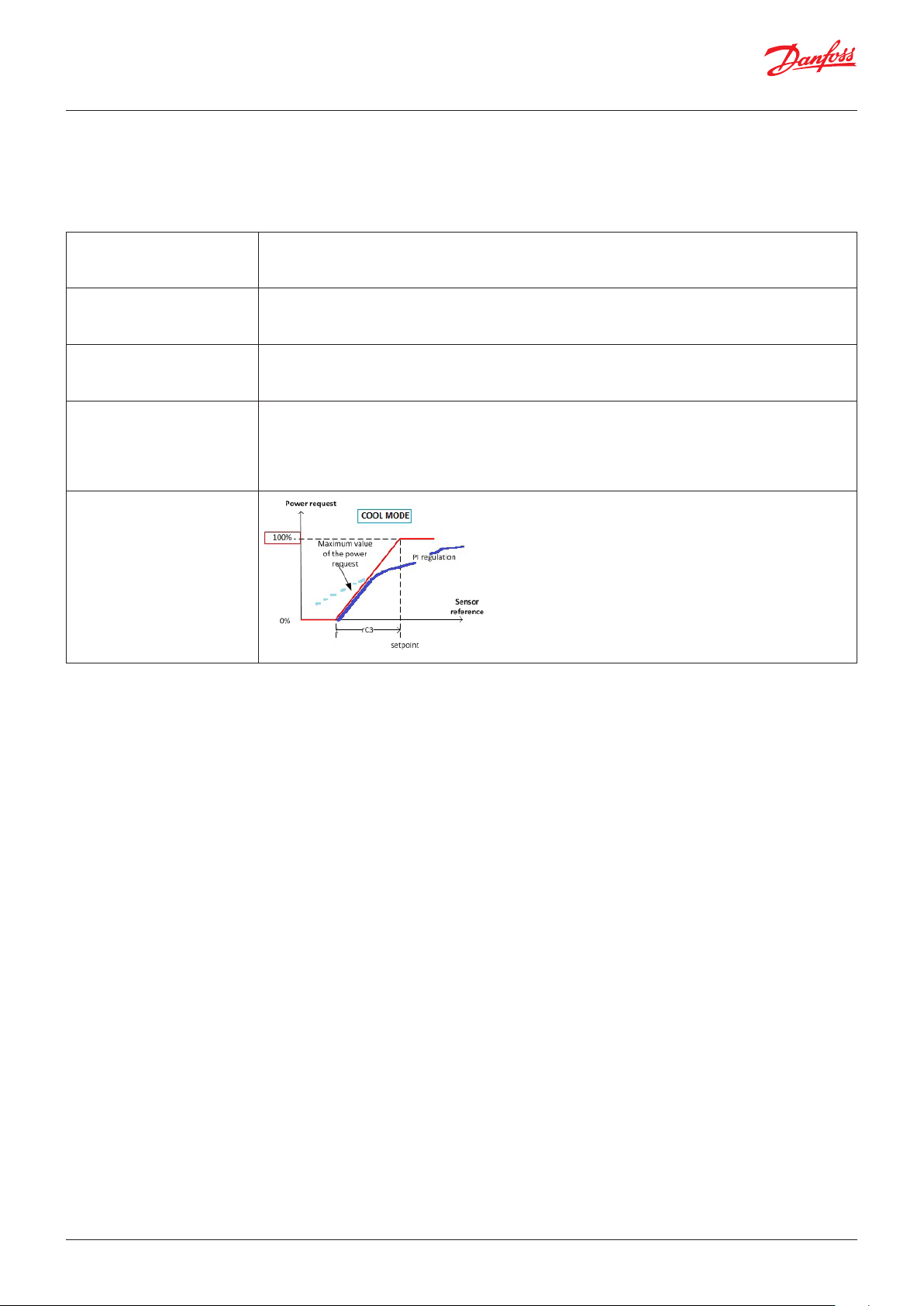
PI regulation
Parameter: CrC1, rH1, Rin, rC2, rC3
Note: the PI regulation is enabled when the parameter rET is equal to P or PI
rC1-Cooling temperature
differential.
rH1-Heating temperature
differential.
Rin- Ti It is the integral time of the PI regulation, the bigger the value of Rin the slower the action of the
rC2-Cut Off enable It enables the gradual reduction of the integral error once reached and exceeded the setpoint. The
rC3- Cut off offset
See parameter rET
See parameter rET
Integral part.
See parameter rET
error integral in fact tends to keep the compressors turned on even if the proportional part of the
error would require a shutdown. The amount of reduction is proportional to the distance from the
setpoint considering the rC3 band. For example, in cooling, the reduction is zero when the control
temperature is equal to the setpoint; the reduction is greatest when it is equal to setpoint-rC3.
© Danfoss | DCS (vt) | 2019.08 BC295150867120en-000201 | 27
Page 28
User Guide | Chiller and reversable chiller, reciprocating, scroll and screw compressors
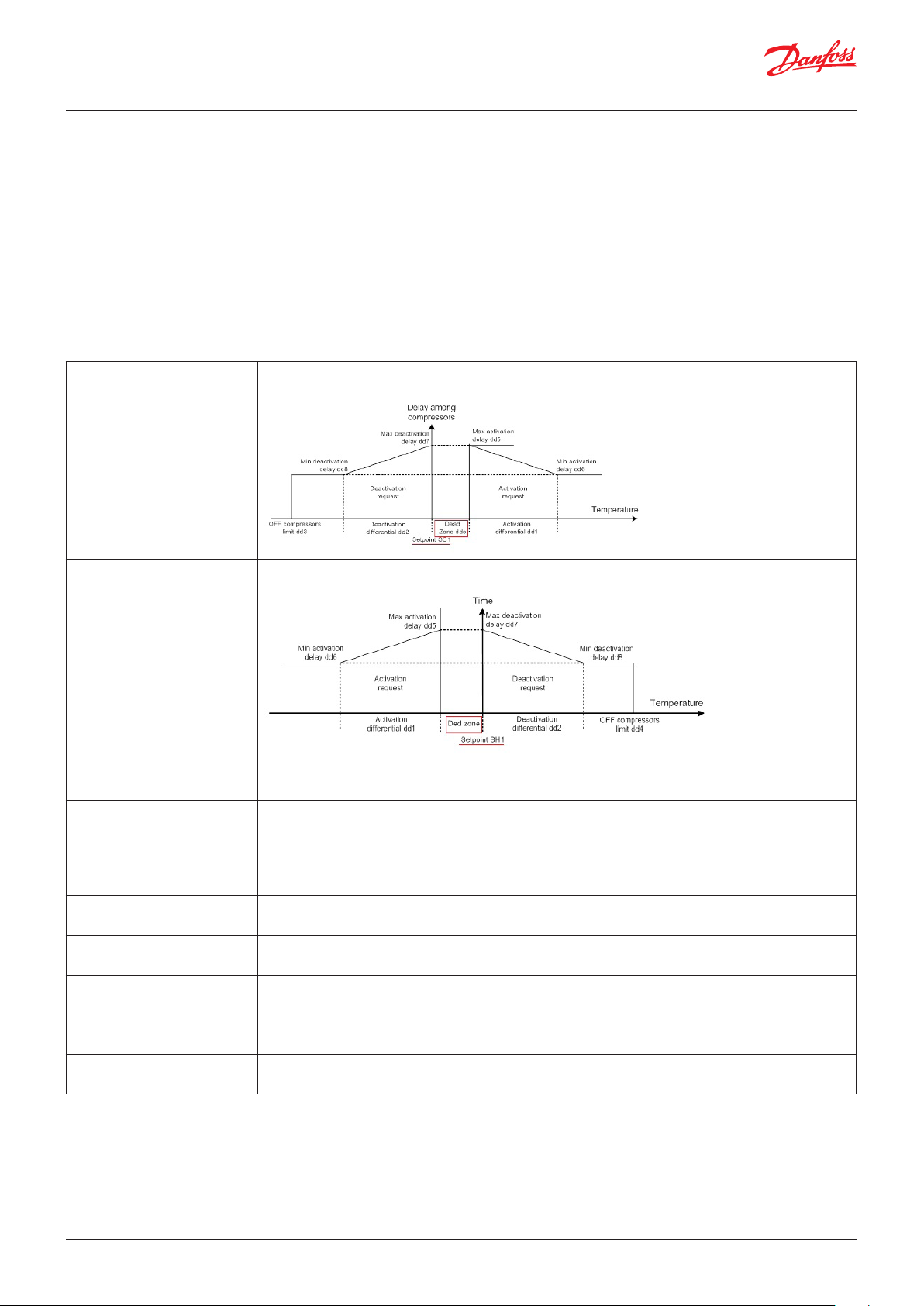
Dead zone regulation
Parameter: ddC, ddH, dd1, dd2, dd3, dd4, dd5, dd6, dd7, dd8
Functionalities: Enable Dead Zone Regulation
The dead zone regulation is enable when the parameter rET is equal to DZ
It is a variable time regulation mainly used when the regulated value is the
temperature of the fluid leaving the evaporator.
In the dead zone ddC no regulating action is taken.
Close to the dead zone the decision to cut the compressor in or out will
take a maximum time of (dd5 or dd7), a time that will decrease linearly
outside the dead zone. This variable time logic is described below.
ddC-Cooling dead zone In dead zone ddC no regulation action is taken.
This is above the setpoint and used in cooling mode
ddH-Heating dead zone In dead zone ddH no regulation action is taken.
This is below the setpoint used in heating mode
dd1-Comp activation
differential
dd2-Comp deactivation
differential
dd3-Min temp for OFF comp
in cooling
dd4-Max temp for OFF comp
in heating
dd5-Max delay of comp activation
dd6-Min delay of comp
activation
dd7-Max delay of comp
deactivation
dd8-Min delay of comp
deactivation
Defines the maximum temperature gap to have a minimum delay (dd6) in the compressor’s activation
Note: see picture in the parameter ddC and ddH
Defines the maximum temperature gap to have a minimum delay (dd6) in the compressor’s
deactivation
Note: see picture in the parameter ddC and ddH
Defines the minimum temperature below which the compressors are switched off
Note: see picture in the parameter ddC
Defines the maximum temperature above which the compressors are switched off
Note: see picture in the parameter ddH
Defines the maximum delay before a compressor cuts in
Note: see picture in the parameter ddC and ddH
Defines the minimum delay before a compressor cuts in
Note: see picture in the parameter ddC and ddH
Defines the maximum delay before a compressor cuts off
Note: see picture in the parameter ddC and ddH
Defines the minimum delay before a compressor cuts off
Note: see picture in the parameter ddC and ddH
28 | BC295150867120en-000201 © Danfoss | DCS (vt) | 2019.08
Page 29
User Guide | Chiller and reversable chiller, reciprocating, scroll and screw compressors
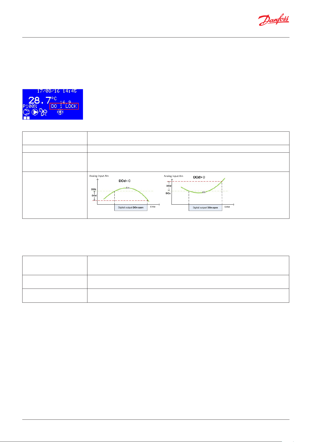
Digital output lock
Parameter: DOn, Ain, Dos, DOd
It is possible to lock a digital output in open position in relation to
an analogue input.
The lock condition is reported in the rolling text
Functionalities: Enable DO Locking from AI
DOn-Digital output number This is the number of the digital output to lock in open position;
The conditions to lock it are defined by AIn, DOs and DOd
AIn-Analogue input number This is the number of the analogue input to refer to lock the digital output DOn
DOs-Set point for locking This is the setpoint to compare with the value of the analogue input AIn for locking the digital output
DOn;
Note: set parameter DOd to lock the digital output DOn above or below the setpoint DOs
DOd-Differential to unlock
Buzzer and relay
Parameter: BUZ, Adl, AOF
BUZ-Buzzer activation time
number
Adl-Alarm relay activation
delay
AOF-Alarm relay active if unit
in off
It's in minutes.
Defines the maximum time that the buzzer can work;
BUZ=15 means that there is no limit in the active time of buzzer
It's in seconds.
Defines the delay of the alarm relay when there is an alarm
Defines whether the alarm relay works in the OFF state of the chiller
© Danfoss | DCS (vt) | 2019.08 BC295150867120en-000201 | 29
Page 30

User Guide | Chiller and reversable chiller, reciprocating, scroll and screw compressors
Flow alarm
Parameter: AFr, AF1, AF2, AF3
It is generated by the “Flow Evaporator” digital input.
In the event of an alarm:
• if there is the second pump “Evap Pump2”, the second pump
operating warning A08 will be activated before the flow switch
alarm A03;
• otherwise, all the compressors and all the other elements will be
immediately switched OFF, ignoring their protection times.
The alarm is delayed by AF1 seconds after the pump starts to
wait for the water flow to reach its steady value.
It is also delayed in normal functioning by AF2 seconds to filter
out temporary flow changes or air bubbles in the water circuit.
AFr-Reset Type Used in the alarm tab to set the reset type from the UI
The reset type is configurable through AFr to:
• manual: all the outputs are OFF, including the pump. After reset,
if the alarm is still active, the alarm is ignored (but still shown on
display) until the delay time from startup is elapsed to give the
unit the chance to start normally.
• automatic: all the outputs are OFF, excluding the pump which
tries to start every AF3 seconds; the alarm is ignored until the
delay time from startup is elapsed.
• semi-automatic: the pump tries to start every AF3 seconds for
AFr number of times, ignoring the alarm during its delay at
startup; exceeded the attempts of starting the pump, the alarm
can only be reset manually.
Digital input: FPE
Alarms: A03, A08
AF1-Delay from pump starting Used in the alarm tab to set the Startup delay from the UI
Note: Period starts when the pump starts and not from the power being turned on
AF2-Delay in steady operation Used in the alarm tab to set the Steady delay from the UI
AF3-Time to restart Defines the time to wait before restart the pump;
It works resetting both the automatic and semiautomatic alarms
30 | BC295150867120en-000201 © Danfoss | DCS (vt) | 2019.08
Page 31

User Guide | Chiller and reversable chiller, reciprocating, scroll and screw compressors
ICE alarm
Parameter: AIS, AID, Air, AI1, AI2, AI3, AIT, AIo
Analogue input: TO1, TO2, TO3, TO4, TOUt
Alarms: AE1, AE2, AE3, AE4, AIT
Functionalities: Enable enhanced low temperature management
AIS-Ice alarm setpoint If TOx temperature goes below AIS °C the alarm AEx (x=1,2,3,4) is detected
ICE Alarm cuts in the heaters
Note: see parameter AI3 to set up the alarm’s behaviour in the OFF state
AID-Differential Above AIS +AID the ICE alarm is resettable
AIr-Reset Type Used in the alarm tab to set the reset type from the UI
AI1-Delay from pump starting
in cool
AI2-Delay from pump starting
in heat
AI3-Out status if unit
OFF - alarm
AIT-Ice tout alarm It’s in °C
AIo-Ice alarm offset It’s in °C
It’s in seconds
Used in the alarm tab to set the “Startup delay” from the UI
Used for the cooling mode
It’s in seconds
Defines the delay of the ice alarm from the pump starting in heating mode
Defines the chiller’s behaviour in relation to the ICE alarm when the chiller is in OFF state
0=HOFF means that the heaters will not be used
1=HON means that only the heaters will switch ON
2=HPON means that pump and heaters both will switch ON
Note: in the ON state the ICE Alarm switches on the heaters
If external temperature Tout goes below AIT °C, alarm AIT is generated
Note: the action of the alarm has to be defined in the alarm tab
The setpoint of the ice alarm becomes AIS+Alo, the sensor used to check the alarm is the minimum
in between Tin, TOx, TFC and Tout
Note: The functionality “Enable enhanced low temperature management” is required
© Danfoss | DCS (vt) | 2019.08 BC295150867120en-000201 | 31
Page 32

User Guide | Chiller and reversable chiller, reciprocating, scroll and screw compressors
Compressor oil delta pressure alarm
Parameter: OPR, OdP, GdP
The alarm is detected when the compressor runs.
The alarm A4x is triggered when the difference in between
the sensor defined by parameter OPR and the sensor OPx_Oil
pressure Compx is lower than OdP.
Alarm behavior has to be set in the Alarm tab
Analogue input: OP1, …, OP8, SP1, …, SP4, dP1, …, dP4
Alarms: A31, …, A35, A41, …, A48, dP0, dP1, …, dP4
OPR- Oil delta pressure
reference
OdP- Min oil delta pressure Measurements are in bar
GdP- Min gas delta pressure Measurements are in bar
0=SUC means that the alarm depends on suction pressure
1=DIS means that the alarm depends on discharge pressure
Note: check parameter H42
Defines the minimum delta pressure to generate the alarm
Alarm hysteresis is fixed and equal to 0.3 bar
When the gap between discharge and suction pressure is less than GdP bar the alarm dPx
is generated
Alarm hysteresis is fixed and equal to 0.3 bar
Note: The alarms have to be set in the alarm tab
Circuit high temperature alarm
Parameter: HTs, HTd
When the discharge temperature of the circuit is above HTs
parameter the “High discharge temp” alarm is generated.
When the discharge temperature goes below HTs-HTd the alarm
can be reset
Analogue input: dt1, dt2, dt3, dt4
Alarms: dt0, dt1, dt2, dt3, dt4
HTs- High discharge
temperature set
Defines the temperature setpoint above which the dtx alarm is generated
HTd- Differential Below HTs-HTd the alarm can be reset
32 | BC295150867120en-000201 © Danfoss | DCS (vt) | 2019.08
Page 33
User Guide | Chiller and reversable chiller, reciprocating, scroll and screw compressors
Pressure alarms from analogue input
Parameter: AHE, AHS, AHd, Alr, AL1, AL2, ALE, ALS, ALd, LPt, AVO, VCt, SHS, SHb
Analogue input: dP1, dP2, dP3, dP3, SP1, SP2, SP3, SP4
Alarms: AH0, AH1, AH2, AH3, AH4, AL0, AL1, AL2, AL3, AL4, AV0,
AV1, AV2, AV3, AV4, AM0, AM1, AM2. AM3, AM4
AHE- Enable HP alarm from AI 0=NO means disable
1=YES means enable
AHS- High pressure alarm
setpoint
AHd- High pressure alarm
hysteresis
Alr- Reset type Used in the alarm tab to set the reset type from the UI
When the discharge pressure (sensor dPx) goes above AHS, alarm AHx is triggered
Below AHS-AHd the alarm AHx can be reset
AL1- Delay from compressor
starting
AL2- Enable when compressor
OFF
ALE- Enable LP alarm from AI 0=NO means disable
ALS- Low pressure alarm
setpoint
ALd Low pressure alarm
hysteresis
© Danfoss | DCS (vt) | 2019.08 BC295150867120en-000201 | 33
Used in the alarm tab to set the startup delay from the UI
0=NO means that the low pressure alarm is not triggered when the circuit is switched off
1=YES means that the low pressure alarm is triggered also when the circuit is switched off
1=YES means enable
Note: it enables also the vacuum alarm
When the suction pressure (sensor SPx) goes below ALS alarm ALx is triggered
Above ALS+ALd the alarm ALx can be reset
Page 34
User Guide | Chiller and reversable chiller, reciprocating, scroll and screw compressors
LPt- Low pressure bypass time Used in the alarm tab to set the Steady delay from the UI
AVO- Vacuum alarm offset When the suction pressure (sensor SPx) goes below ALS-AVO alarm AVx is triggered
Note: The alarm is enabled by ALE (the same used for Low pressure alarm)
AVd- Vacuum alarm hysteresis Above ALS- AVO + AVd the alarm AVx can be reset
VCt-Vacuum alarm bypass
time
SHS- High suction pressure
setpoint
SHb- High suction pressure
hysteresis
Used in the alarm tab to set the Steady delay from the UI
When the suction pressure (sensor SPx) goes above ASH, alarm AMx is triggered
Below SHS-SHb the alarm AMx can be reset
High water temperature alarm in cooling mode
Parameter: Ats, Atd
Analogue input: TOx
Alarms: A09
Ats- Setpoint in cooling In Cooling mode, when the water temperature (max in between TOx) goes above Ats, the alarm A09
is triggered
Note: The alarm’s action has to be set in the alarm tab
Atd- Differential Below Ats-Atd the alarm A09 can be reset
Boiler water temperature alarm
Parameter: AbS, Abd
It works only for heat pump configuration H40> 0 (heat pump)
and H41> 0 (Boiler with heaters)
The alarm A14 deactivates the heaters
Analogue input: BOI
Digital output: BOx
Alarms: A14
AbS- Setpoint When the water inside the boiler (BOI) goes above AbS, the alarm A14 is triggered
Alarm A14 deactivates the heaters
Abd - Differential Below Abs-Abd the alarm A14 can be reset
34 | BC295150867120en-000201 © Danfoss | DCS (vt) | 2019.08
Page 35
User Guide | Chiller and reversable chiller, reciprocating, scroll and screw compressors
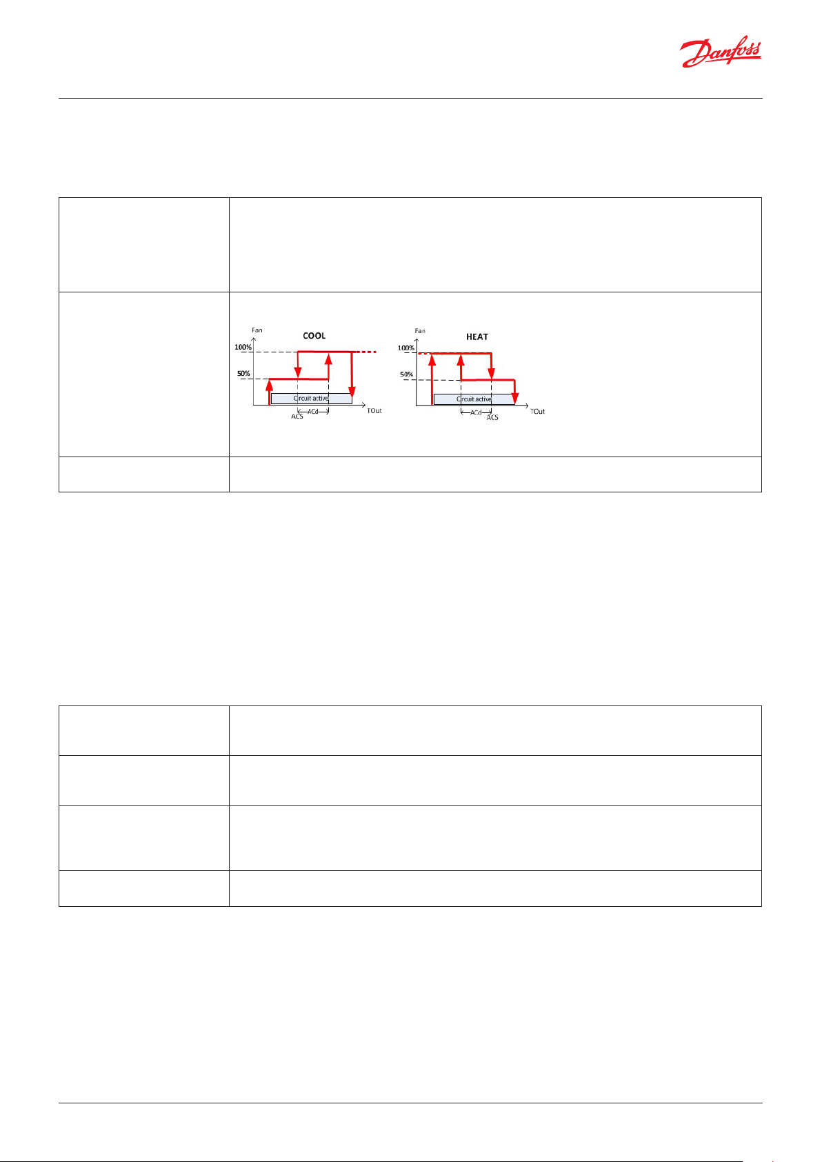
Fault of the regulation probe of the external coil
Parameter: ACM, ACS, ACd
How set it up
ACM- Condenser fan/pump
status
ACS- Outside temp set for
fan/ pump
ACd- Outside temp diff. for
fan/pump
0=OFF means that if there is a condenser regulation probe fault, the Fan/Pump will be kept switched
OFF
1=ON_C means that if there is a condenser regulation probe fault, the Fan/pump will be switched ON
if at least one compressor is active in the circuit
2=FTou means that if there is a condenser regulation probe fault, the Fan/Pump will cut in in relation
to the TOut_ T out sensor, see parameter ACS and ACd
If ACM=FTou, in case of fault of condenser regulation probe, the fan will regulate in relation to the
outside temperature, following the picture below
Note. In case of outside temperature sensor fault the fan will works as ACM=ON_C
See parameter ACM
Preventions
Parameter: TMx, THo, TLo, HPE, HPo, HPh, LPE, LPo, LPh, PPt, PPp, HFo
The alarm's action has to be set in the alarm tab.
Info on prevention status through rolling text
Functionalities: Enable compressor high temperature prevention
Analogue input: CTx, dPx, SPx
Alarms: CTx, A8E, A8F
TMx- Max compressor
temperature
THo- Comp Max Temp Prev
Offset
TLo- Comp Max Temp Prev Diff It’s in °C
HPE- HP prevention enable 0=NO means disable
It’s in °C
When the temperature CTx goes above TMx the alarm CTx is triggered.
Note: the action of the alarm has to be defined in the alarm tab
It’s in °C
When the temperature CTx goes above TMx-THo, the screw compressor is set to minimum power
Note: it works only for screw compressors
When the temperature CTx goes below TMx-THo-TLo, the screw compressor restart to work with-
out limitation
Note: it works only for screw compressors
1=YES means enable
© Danfoss | DCS (vt) | 2019.08 BC295150867120en-000201 | 35
Page 36

User Guide | Chiller and reversable chiller, reciprocating, scroll and screw compressors
HPo- HP prevention offset When the high pressure sensor goes above AHS-HPo, every PPt seconds the prevention decreases
the circuit power request by PPp
HPh- HP prevention hysteresis When the high pressure sensor goes below AHS-HPo -HPh, every PPt seconds the prevention in-
creases the circuit power request by PPp
Note: See HPo parameter
LPE- LP prevention enable 0=NO means disable
1=YES means enable
LPo- LP prevention offset When the low pressure sensor goes below ALS+LPo, every PPt seconds the prevention decreases
the circuit power request by PPp
LPh- HP prevention hysteresis When the low pressure sensor goes below ALS+LPo +LPh, every PPt seconds the prevention
increases the circuit power request by PPp
Note: See LPo parameter
PPt-Pressure decreasing
power period
PPp-Pressure decreasing
power %
HFo-HP fan offset Defines the offset to add /subtract to the setpoint FHS /FCS during the prevention
It is the period in between 2 corrections of the power request during the prevention
It is the correction (%) of the power request during the prevention
Note: if HFo=0 is like disable this function
36 | BC295150867120en-000201 © Danfoss | DCS (vt) | 2019.08
Page 37
User Guide | Chiller and reversable chiller, reciprocating, scroll and screw compressors
Superheat alarms
Parameter: SHh, AHI, Ahi, AHd
It gives the possibility to set a range outside which the superheating
triggers an alarm;
The alarm’s behaviour has to be set in the alarm’s tab
Functionalities: Enable superheating alarm on low and high values
Alarms: SL1, SL2, SL3, SL4, SH1, SH2, SH3, SH3
SHh-Max superheat temp If the superheat goes above SHh alarm is triggered
SHl-Min superheat temp If the superheat goes below SHl alarm is triggered
SHi-Alarm hysteresis The alarms can be reset only in between SHl+SHi and SHh-SHi
SHd-Superheat alarm delay Used in the alarm tab to set the “Steady delay” from the UI
Oil temperature alarms
Parameter: OTm, OTi, OTd
Allows the temperature to be set above the level where an oil’s
alarm is triggered;
The alarm’s behaviour has to be set in the alarm’s tab
Functionalities: Enable compressors oil temperature alarm
Analogue input: OT1, OT2, OT3, OT4, OT5, OT6, OT7, OT8
Alarms: OT1, OT2, OT3, OT4, OT5, OT6, OT7, OT8
OTm-Max oil temperature If the oil’s temperature goes above OTm alarm is triggered
OTi-Oil temp hysteresis The alarms can be reset only below OTm-OTi
OTd -Oil temp alarm delay Used in the alarm tab to set the “Steady delay” from the UI
© Danfoss | DCS (vt) | 2019.08 BC295150867120en-000201 | 37
Page 38

User Guide | Chiller and reversable chiller, reciprocating, scroll and screw compressors
Screw compressors
Parameter: C01, C02, CSO, CSb, T1, T2,T3, T4, C07, C08, T5, T6, T21, T22, T24, T24, T25, T26, T27, T28, T29
Only 1 screw compressor per circuit can be managed bot in step
and stepless mode.
Functionalities: Enable screw compressors
Analogue output: CxV, PVx
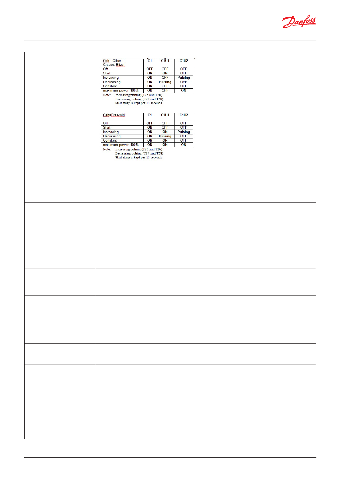
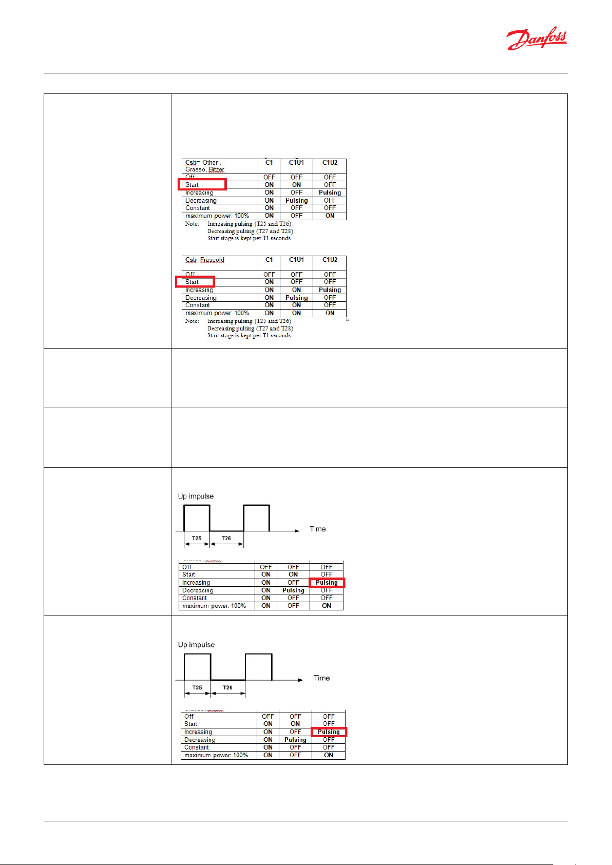
Digital output: C1, C1U1, C1U2, C1U3, C1U4, C2, C2U1, C2U2,
C2U3, C2U4, C3, C3U1, C3U2, C3U3, C3U4, C4, C4U1, C4U2,
C4U3, C4U4
C01- Rotation type Defines the start order of the compressors
0=LIFO means that there is no rotation and the last compressor to be cut in is the first compressor to
be cut out, the cut-in order is C1,C2…Cn, and the cut-out order is Cn…C2, C1
1=FIFO means that there is no rotation and the first compressor to be cut in is the first compressor to
be cut out, the cut-in order is C1,C2…Cn, and the cut-out order is C1,C2…Cn
2=tIME means running hours control; the compressor to be started is the one with the lowest
number of run hours; the compressor to be stopped is the one with the highest number of run hours.
3=BIN means binary logic, it works only for 2 compressors:
• Below 33% of power request, works only C1
• Between 33% and 66% of power request, works C2
• Above 66% both compressors are allowed to work
2=SRM: Reserved
C02- Compressor type Defines the type of compressors
0=SCW means that the compressors are screw type, check parameters CS0 and CSb
1=StD means that the compressors are standard type (not screw type)
CS0- Capacity control mode Defines whether the screw compressor works in step or stepless mode
0=STeP means that the screw compressor provides predefined steps of power, parameter H7 must
be equal 3.
Note: the digital outputs CxU4 (the ones which pulse) are replicated on analogue outputs PVx
The period of pulsing is 2*C07, the contact stays closed per CO7 seconds
1=LESS means that the screw compressors provides modulating power, parameters H7 and IV0
must be equal 0
Note: the analogue output CxV is the compressor x power request
38 | BC295150867120en-000201 © Danfoss | DCS (vt) | 2019.08
Page 39
User Guide | Chiller and reversable chiller, reciprocating, scroll and screw compressors
Note: this parameter works only for C02=0
CSb- Compressor brand Defines if the compressor’s brand and so the behavior of digital outputs. See also parameter CS0
0=Other
1=Fras
2=Bitz
3=Gras
T1-Min time step1/ stepless
startup
T2-Min time step2 It's in seconds
T3-Min time step3 It's in seconds
T4-Min time step4 It's in seconds
C07- Unloaders for pulsing
time
C08- Unloaders Stop delay It’s in seconds
T5-Special management step1 It enables the functionalities of the parameter T6
T6-Max time step1 It's in seconds,
T21-Balance power
distribution
It's in seconds:
• For step compressor (CS0=0): the minimum time that the 1st step has to be kept before increase/cut
off the compressor’s power
• For stepless compressor (CS0=1): The minimum time that the start stage has to be kept before
increase/decrease the compressor’s power
Note: check parameter CS0, T5, T6
• For step compressor (CS0=0): the minimum time that the 2nd step has to be kept before
increase/ decrease the compressor’s power
Note: check parameter CS0
• For step compressor (CS0=0): the minimum time that the 3rd step has to be kept before
increase/ decrease the compressor’s power
Note: check parameter CS0
• For step compressor (CS0=0): the minimum time that the 4th step has to be kept before
increase/ decrease the compressor’s power
Note: check parameter CS0
It’s in seconds
The CxU4 output pulses C07 seconds opened and C07 seconds closed
Note: it only works for screw step compressors (CS0=0)
Defines the minimum time that the power step of the compressor has to be kept before
increase/ decrease power
0=No
1=Yes
For step compressor (CS0=0), defines the maximum time that the compressor can keep step1,
after that the compressor’s power will be increased
Note: check parameter CS0 and T5
Used for stepless screw compressor.
0=No means that before cutting in a new compressor, the compressors which are working have to be
at maximum power; before decreasing the compressor power, a compressor has to be switched off
1=Yes means that before increasing a compressor’s power, all the compressors have to be switched on
© Danfoss | DCS (vt) | 2019.08 BC295150867120en-000201 | 39
Page 40
User Guide | Chiller and reversable chiller, reciprocating, scroll and screw compressors
T22-Minimum power Used for stepless screw compressor.
It’s in %
Defines the minimum power request (in the circuit) above which the compressor is switched on.
After this Start stage of the compressor the compressor will be allowed to work
Note: check parameter T1
T23-Valve opening time Used for stepless screw compressor.
It’s in seconds
Defines the minimum time that the compressor spends to reach maximum power starting from the
start position
Note: depends on the Pulsing period - check parameters T25 and T26
T24-Valve closing time Used for stepless screw compressor.
It’s in seconds
Defines the minimum time that the compressor spends to reach the minimum power starting from
maximum power
Note: depends on the Pulsing period - check parameters T27 and T28
T25-Minimum time UP
impulse
Used for stepless screw compressor.
It's in milliseconds
T26-OFF time in between
UP impulses
40 | BC295150867120en-000201 © Danfoss | DCS (vt) | 2019.08
Used for stepless screw compressor.
It's in seconds
Page 41
User Guide | Chiller and reversable chiller, reciprocating, scroll and screw compressors
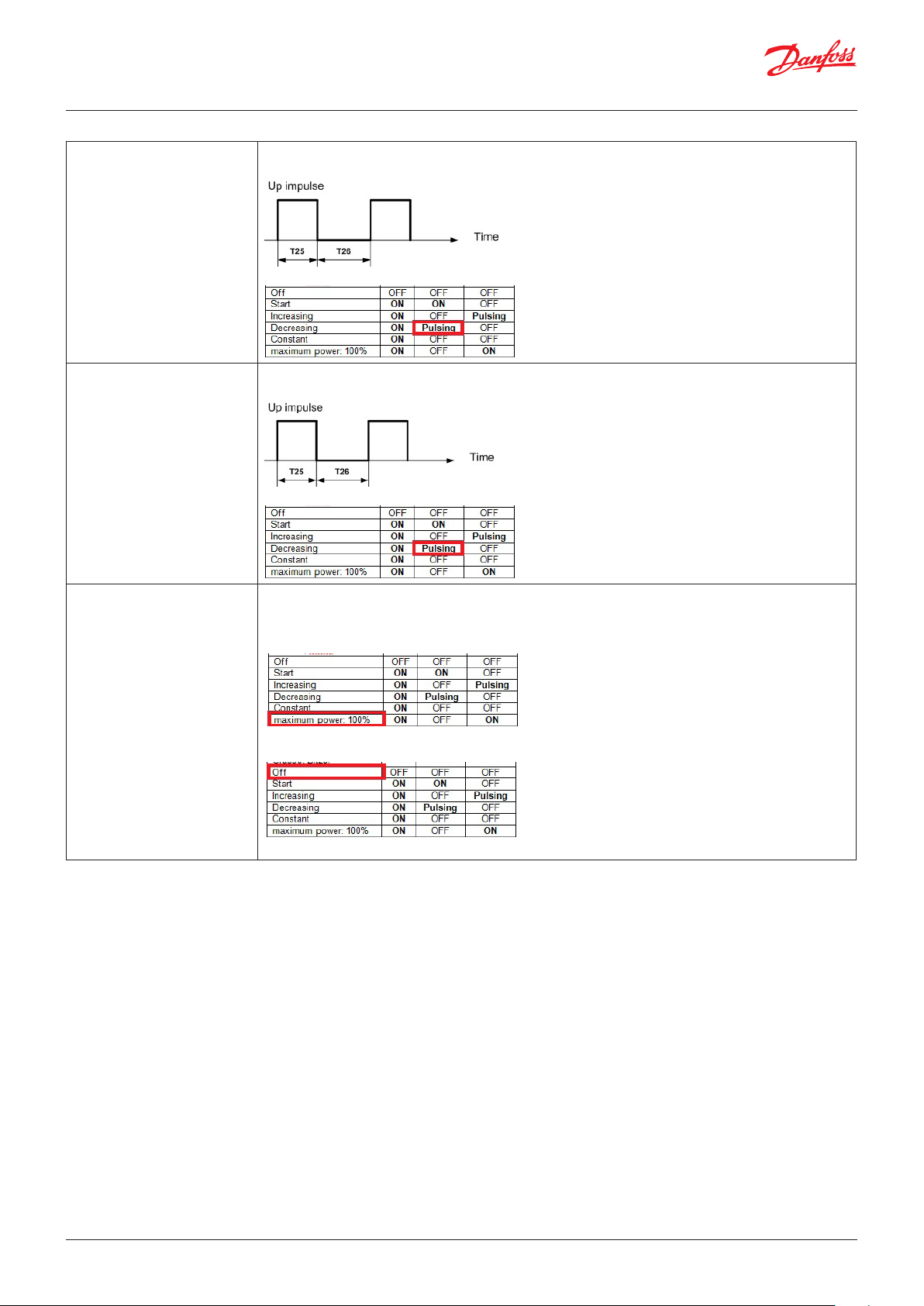
T27-Minimum time
DOWN impulse
T28-OFF time in between
DOWN impulses
T29-% limit for max Open/
Close
Used for stepless screw compressor.
It's in milliseconds
Used for stepless screw compressor.
It’s in seconds
Used for stepless screw compressors.
It’s in %
When the circuit’s power request goes above (100-T29)% the compressor reaches the “Maximum
power 100%” stage
When the circuit’s power request goes below T29% the compressor is switched off
© Danfoss | DCS (vt) | 2019.08 BC295150867120en-000201 | 41
Page 42

User Guide | Chiller and reversable chiller, reciprocating, scroll and screw compressors
Starting type of the compressor
Parameter: Sty, Sti, SSt, Stm, Sdd
For the start of big compressors is possible to select a
PARTWINDING logic or STAR-DELTA logic
Functionalities: Enable motor starting type selection
Digital output: C1, C1P,C1S, C1D, C2, C2P, C2S, C2D, C3, C3P, C3S,
C3D, C4, C4P, C4S, C4D, C5, C5P, C5S, C5D, C6, C6P, C6S, C6D, C7,
C7P, C7S, C7D, C8, C8P C8S, C8D
Sty-Starting type Defines how to start a compressor in order to limit the start current
0=Dir : Direct start of the compressor (only Cx digital output)
1=PWin : Part winding start of the compressor (Cx and CxP digital outputs)
2=StDe : Star-Delta start of the compressor (Cx , CxS and CxD digital outputs)
Sti-Part winding delay It’s used for part winding starting type (Sty=1).
It's in milliseconds
Just Sti milliseconds after the start of the xth compressor (Cx= Closed) the digital output CxP is closed
SSt-Compressor start delay It’s used for “star-delta” starting type (Sty=2).
It's in milliseconds
Just SSt milliseconds before the start of the xth compressor (Cx= Closed) the digital output CxS is closed
Stm-Star time It’s used for “star-delta” starting type (Sty=2).
It's in milliseconds
It’s defines how long the star stage will be kept, the digital output Cxs will be opened after Stm
milliseconds from the compressor start (Cx=Closed)
Sdd-Star-Delta delay It’s used for “star-delta” starting type (Sty=2).
It’s in milliseconds
It’s defines the delay between the closing of the “Delta” connection (CxD=Closed)
from the opening of the “Star” connection (CxS=Closed)
42 | BC295150867120en-000201 © Danfoss | DCS (vt) | 2019.08
Page 43
User Guide | Chiller and reversable chiller, reciprocating, scroll and screw compressors
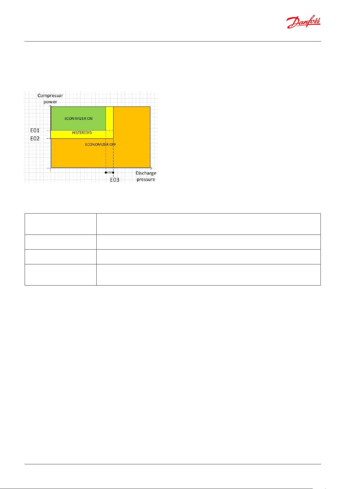
Economizer
Parameter: E01, EO2, EO3, EO4
The logic to manage the economizer considers one compressor
per circuit, like in the case of screw compressors
Digital output: EC1,EC2, EC3, EC4
Analogue input: dp1. dp2, dp3,dp4
E01-ON Setpoint It’s in %
When the compressor’s power is >= E01% and the discharge pressure is below E03-E04, the
economizer (digital output ECx) is opened
E02-OFF Setpoint It’s in %
When the compressor’s power is <= E02% the economizer (digital output ECx) is closed
E03-Pressure limit It’s in bar G
When the compressor’s power is >= E03 bar, the economizer (digital output ECx) is closed
E04-Pressure differential It’s in bar G
When the compressor’s power is >= E01% and the discharge pressure is below E03-E04 the
economizer (digital output ECx) is opened
© Danfoss | DCS (vt) | 2019.08 BC295150867120en-000201 | 43
Page 44

User Guide | Chiller and reversable chiller, reciprocating, scroll and screw compressors
Liquid injection
Parameter: T41, T42, T43, T44, T45
Liquid injection is managed in relation to the discharge
temperature and/or the value of the super heat
It’s designed for only one compressor per circuit.
Functionalities: Enable compressor’s liquid injection
Functionalities: Enable EEV
Digital output: LI1, LI2, LI3, LI4
Analogue input: dT1, dT2, dT3, dT4, and the value of
the superheat
T41-Discharge temperature set It’s in °C
When the discharge temperature " dTx" goes above T41 and compressor x is switched ON, liquid
injection valve "LIx" is opened
T42-Differential It’s in °C
When the discharge temperature "dTx" goes below T41 – T42, liquid injection valve "LIx" is closed.
Note: if the compressor is switched off, the valve is closed
T43-EEV SH Offset It’s in °C
When liquid injection x is working, the maximum SH of circuit x becomes T44-T43 and the minimum
SH becomes T45-T43
Note: Overread is on EXD or EKE drivers or in the internal SH drivers
T44- EEV SH Max It’s in °C
It has to be equal to the maximum SH used in the SH control logic (parameter N09)
T45- EEV SH Min It’s in °C
It has to be equal to the minimum SH used in the SH control logic (parameter N10)
Compressor with unloaders
Parameter: C04, C05, C06, C08
A compressor with unloaders means a compressor able to share
the power load in several stage.
The number of stage is defined by parameter H7
In the single compressor the activation of the unloader follows a
fixed sequence ( Cx->CxU1->CxU2>CxU3->CxU4)
Digital output: C1, C1U1, C1U2, C1U3, C1U4, C2, C2U1, C2U2,
C2U3, C2U4, ….. C8, C8U1, C8U2, C8U3, C8U4,
Note: Parameter H7 has to be > zero
C04- Unloaders activation mode
C05- Unloaders deactivation
mode
C06- Unloaders start delay It’s in seconds
C08- Unloaders Stop delay It’s in seconds
Defines how the increasing of the power between the compressors is managed
0=Cp: activation sequence is C1->C1U1->C1U2->… C2->C2U1 (saturation)
1=CCp: activation sequence is C1->C2->C1U1-> …-> C1U4 -> C2U1->…-> C1U4 (Cut in all the com-
pressors and saturate them one by one)
2=CCp1: activation sequence is C1->C2->C1U1->C2U1 … (Distribution)
Defines how the decreasing of the power in between the compressors is managed
0=pCpC : deactivation sequence is C1U4->…C1U1->C1->C2U4-C2U1->C2 (saturation)
1=ppCC : deactivation sequence is C1U4-> C2U4-> C1U3-> C2U3->…C1->C2 (distribution)
Start delay C06 among unloaders or between the compressor’s activation and its load step.
Note: It avoids the activation of the compressor at full load.
Defines the minimum time that the power step of the compressor has to be kept before
increase/ decrease power
Note: it is also used in screw management
44 | BC295150867120en-000201 © Danfoss | DCS (vt) | 2019.08
Page 45

User Guide | Chiller and reversable chiller, reciprocating, scroll and screw compressors
Maximum number of compressor starts per hour
Parameter: CT0, CT1, CT2, CT3, CT4, CT5, CT6, CT7
How to
CT0- Minimum ON interval
different comp
CT1- Minimum OFF interval
different comp
CT2- Minimum OFF time It’s in seconds
CT3- Minimum ON time It’s in seconds
CT4- Minimum time between
2 ON same compressor
CT5- Max difference in running
hours
CT6- Delay from evaporator
pump/fan
CT7- Delay from cond
pump/ fan
It’s in seconds
Defines the minimum time between the switching on of different compressors
It’s in seconds
Defines the minimum time between the switching off of different compressors
It does not work for inverter compressor (IV0=1)
Defines the minimum time that the compressor has to stay switched OFF
It does not work for inverter compressor (IV0=1)
Defines the minimum time that the compressor has to stay switched ON
It’s in seconds
Defines the minimum time in between two starts of the same compressor:
It means that if the compressor started at the 8:00:00, it will be allowed to start again after 8:00:00
after CT2 seconds
Note: used to define the maximum number of starts/hour for the compressor
Works only for rotation “time” (C01=tIME).
It's in minutes
If a running compressor becomes older than a compressor switched off more than CT5 minutes, the
logic will switch off the oldest compressor running; It will cause the other compressor to be switched on.
The compressors timing (CT0,…CT4) is respected
It’s in seconds
Defines the minimum delay from the evaporator’s pump before allow the switch on of the compressors.
It’s in seconds
• For the water-water chiller, this defines the time in between the external coil pump cutting in and
the first start of the first compressor in the circuit.
• For the water-air chiller, if CT7 > zero the fan is switched on( F12 %) CT7 seconds before of the first
compressor of the circuit.
After the fan regulation will follow the normal one (check parameter F01)
© Danfoss | DCS (vt) | 2019.08 BC295150867120en-000201 | 45
Page 46

User Guide | Chiller and reversable chiller, reciprocating, scroll and screw compressors
Valve in the liquid line
Parameter: Pd1, Pd2, Pd3, Pd4
Pump down before the circuit’s stop and equalization of the
pressure before circuit’s startup
Digital output: LV1, LV2, Lv3, LV4
Digital input: PD1, PD2, PD3, PD4, LPL1, LPL2, LPL3,LPL4
Analogue input: SP1, SP2, SP3, SP4
Pd1-Pump down enable and
max time
Pd4- Pump down pressure set It’s in bar G
Pd2- Compressor ON delay
from liquid valve
Pd3- Start up suction
pressure set
It’s in seconds
0=Disable
>0=It defines the maximum pump down time.
The liquid valve LVx is closed before switch off the last compressor in the circuit.
The compressor will switch off for the following reasons:
• Low pressure switch (LPLx)
• Suction pressure below Pd4 (SPx< Pd4)
• Pd1 seconds are elapsed from LVx closing
• The digital input PDx is closed (manual pump down)
Note: Pump down is not executed in case of alarm
Note: if the sensor SPx is not present it is not considered
If the pressure of the circuit (SPx) goes below Pd4 during the pump down process the compressor is
switched off
It’s in seconds
Before starting the first compressor in the circuit, the liquid valve is opened in order to decrease the
pressure ratio of the circuit.
The compressor will start if:
• The suction pressure goes above Pd3
• At the maximum after Pd2 seconds from liquid line valve opening
It’s in bar G
See parameter Pd2
46 | BC295150867120en-000201 © Danfoss | DCS (vt) | 2019.08
Page 47

User Guide | Chiller and reversable chiller, reciprocating, scroll and screw compressors
Maximum compressor running hours
Parameter: C50
The hours counters can be reset in the menu, the menu has
password level3
Alarms: A61, A62, A63, A64, A65, A66, A67, A68
C50-Maximum limit It’s in k Hours (1,000 hours)
When the running hours of the compressor Cx goes above C50 the alarm A6x is triggered
© Danfoss | DCS (vt) | 2019.08 BC295150867120en-000201 | 47
Page 48
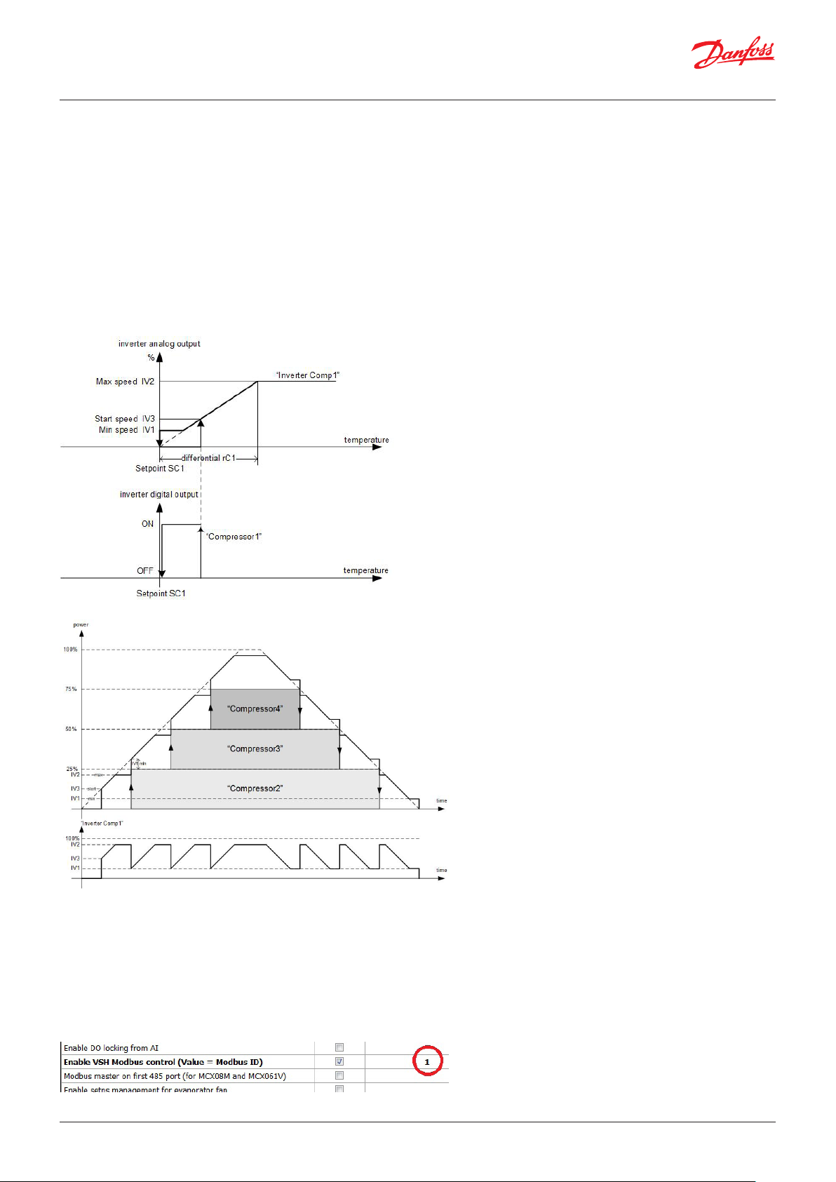
User Guide | Chiller and reversable chiller, reciprocating, scroll and screw compressors
Inverter compressor
Parameter: IV0, IV1, IV2, IV3, IV4, IV5
The inverter compressor will be switched on at first and switched
off last.
The inverter compressor will provide a large range of power.
Below are the inverter behaviours alone or combined with other
ON-OFF compressors
Digital input: OC1
Digital output: C1
Analogue output: C1
Note: the Danfoss Inverters can be driven through Modbus;
Modbus communication reports the status of the inverter in the
MCX user interface. Modbus communication with the inverter
is enabled through the functionalities “Enable VSH Modbus
control(Value=Modbus ID)” , MCX will be master in the Modbus
communication.
It will call the inverter with the ID reported in the functionalities
tab (it can be changed)
48 | BC295150867120en-000201 © Danfoss | DCS (vt) | 2019.08
Page 49

User Guide | Chiller and reversable chiller, reciprocating, scroll and screw compressors
MCX will use the Modbus port 2,
With MCX having only one Modbus port is required to enable
also the functionalities “Modbus master on the first 485 port
(for MCX08 and MCX061V)”
IV0-Inverter enable It enables the managing of the inverter compressor in the compressor C1
0=No
1=Yes
IV1- Minimum speed It’s in %
Defines the minimum speed of the inverter compressor, check also IV3
IV2- Maximum speed It’s in %
Defines the maximum speed of the inverter compressor, check also IV3
IV3- Start speed It’s in %
Defines the request that will switched on the inverter compressor (both Analogue Output and
Digital Output),
IV4- Minimum ON time It’s in seconds
It works only for inverter compressor (IV0=1)
Defines the minimum time that the compressor has to stay switched ON
IV5- Minimum OFF time It’s in seconds
It works only for inverter compressor (IV0=1)
Defines the minimum time that the compressor has to stay switched OFF
© Danfoss | DCS (vt) | 2019.08 BC295150867120en-000201 | 49
Page 50
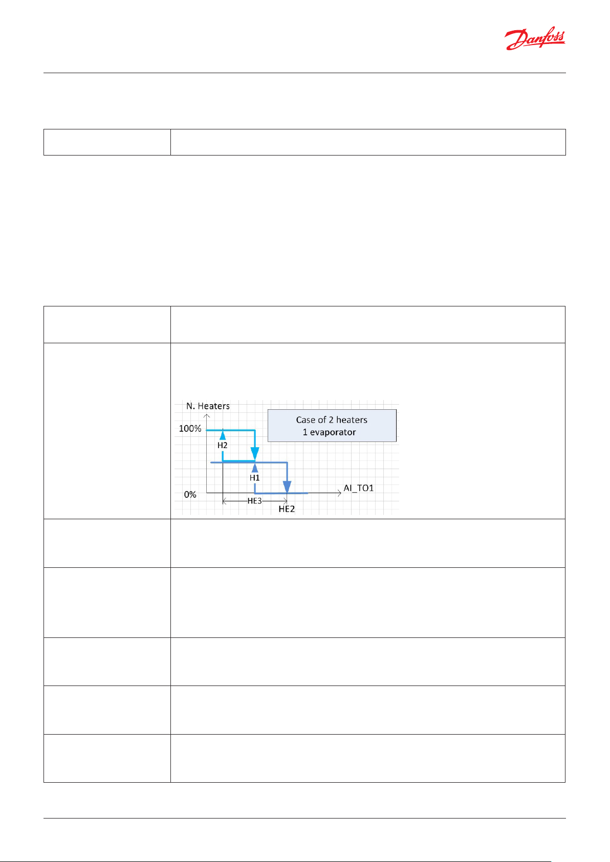
User Guide | Chiller and reversable chiller, reciprocating, scroll and screw compressors
Compressor enabling
Parameter: CT1, CT2, CT3, CT4, CT5, CT6, CT7, CT8
CT1-CTx-CT8
Compressor x enable
0=No : compressor x can work
1=Yes : compressor x cannot work
Heaters
Parameter: HE1, HE2, HE3, HE4, HE5, HE6, HE7
The heaters work:
• for regulation (HE1,HE2 and HE3)
• Ice alarm (AIS, AID AI3)
Digital output: H1, H2, H3, H4
Digital input: OH1, OH2, OH3, OH4, OHL1, OHL2, OHL3, OHL4, OH
Analogue input: TO1, TO2, TO3, TO4
Alarms: A90, A91, A92, A93, A94, Ar1, Ar2, Ar3, Ar4
HE1-Compressor ON/OFF
with heaters
HE2-Heaters setpoint in
cooling
0= ON: compressor can work with the heaters switched on
1= OFF: compressor will be switched off if the heaters are switched on
Note: The times of the compressors (CT0-CT7) are respected
It’s in °C.
It works in cooling mode.
Defines the minimum tout evaporator temperature (TOx) below which the heaters are allowed
to work, the cut-in of the heaters depends on the number of heaters (H5) and the differential
temperature defined by parameter HE3.
HE3-Heaters differential in
cooling
HE4-Heaters setpoint in
Heating
HE5-Heaters differential in
heating
HE6-Heaters offset in cooling It’s in °C.
HE7-Heaters offset in heating It’s in °C.
It's in °C.
Works in cooling mode.
The heaters switched on between HE2 and HE2-HE3 °C
Note: Check parameter HE2
It’s in °C.
It works in heating mode.
Defines the minimum tout evaporator temperature (TOx) below which the heaters are enabled
to works, the cut-in of the heaters depends on the number of heaters (H5) and the differential
temperature is defined by parameter HE5.
Note: check parameter HE2
It’s in °C.
It works in heating mode.
The heaters are switched on between HE4 and HE4-HE5 °C
Note: Check parameter HE2
In cooling mode, the setpoint of the heaters becomes HE2+HE6, the sensor used to control the
heaters are the maximum in between Tin, TOx, TFC and Tout
Note: the "Enable enhaced low temparature managment" is required
In heating mode, the setpoint of the heaters becomes HE2+HE6, the sensor used to control the
heaters are the maximum in between Tin, TOx, TFC and Tout
Note: the "Enable enhaced low temparature managment" is required
50 | BC295150867120en-000201 © Danfoss | DCS (vt) | 2019.08
Page 51

User Guide | Chiller and reversable chiller, reciprocating, scroll and screw compressors
Pump of the internal coil
Parameter: P01, P02, P03, P04
In the case of a gas/water coil (H3=H2O) it is possible to manage
up to 2 pumps in the water line: H4 <3
In the case of a gas/air coil (H3=Air) it is possible to manage up to
8 fans in the air line: H4 <3
Digital output: PE1, PE2, PE3, PE4, PE5, PE6, PE7, PE8
Digital input: FPE, OPE, OPE1, OPE2
Analogue input: TOM, WPR
Analogue output: E1, E2, E3, E4
Alarms: A03, AP0, AP1, AP2, AP3, AP4, AP5, AP6, AP7, AP8
PO1-Evaporator pump/fan
working mode
0= OFF: Pump is always switched off; the flow switch is detected
1= ON: Pump is switched on at the same time as the unit
2= ON_C: Pump is switched on only if there is a request to switch on a compressor, in which case
there will be a power request to cut in the pump; the pump is switched off P02 seconds after the
compressors cut out
3= brSt: Pump is switched on P03 seconds than switched off for P04 minutes.
The compressors can start only if the pump is running.
If the compressor is switched on, the pump keeps running.
PO2-Pump/fan OFF delay from
comp OFF
PO3-Pump ON pulse time It’s in second.
PO4-Pump OFF pulse time It's in minutes
© Danfoss | DCS (vt) | 2019.08 BC295150867120en-000201 | 51
It’s in second.
Defines the minimum time that the pump has to work after compressor is cut off.
Note: It works after the machine is switched OFF only if the compressor was running
This works with parameter P01=brSt, defining the ON time in the pump’s cycle
This works with parameter P01=brSt, defining the OFF time in the pump’s cycle
Page 52
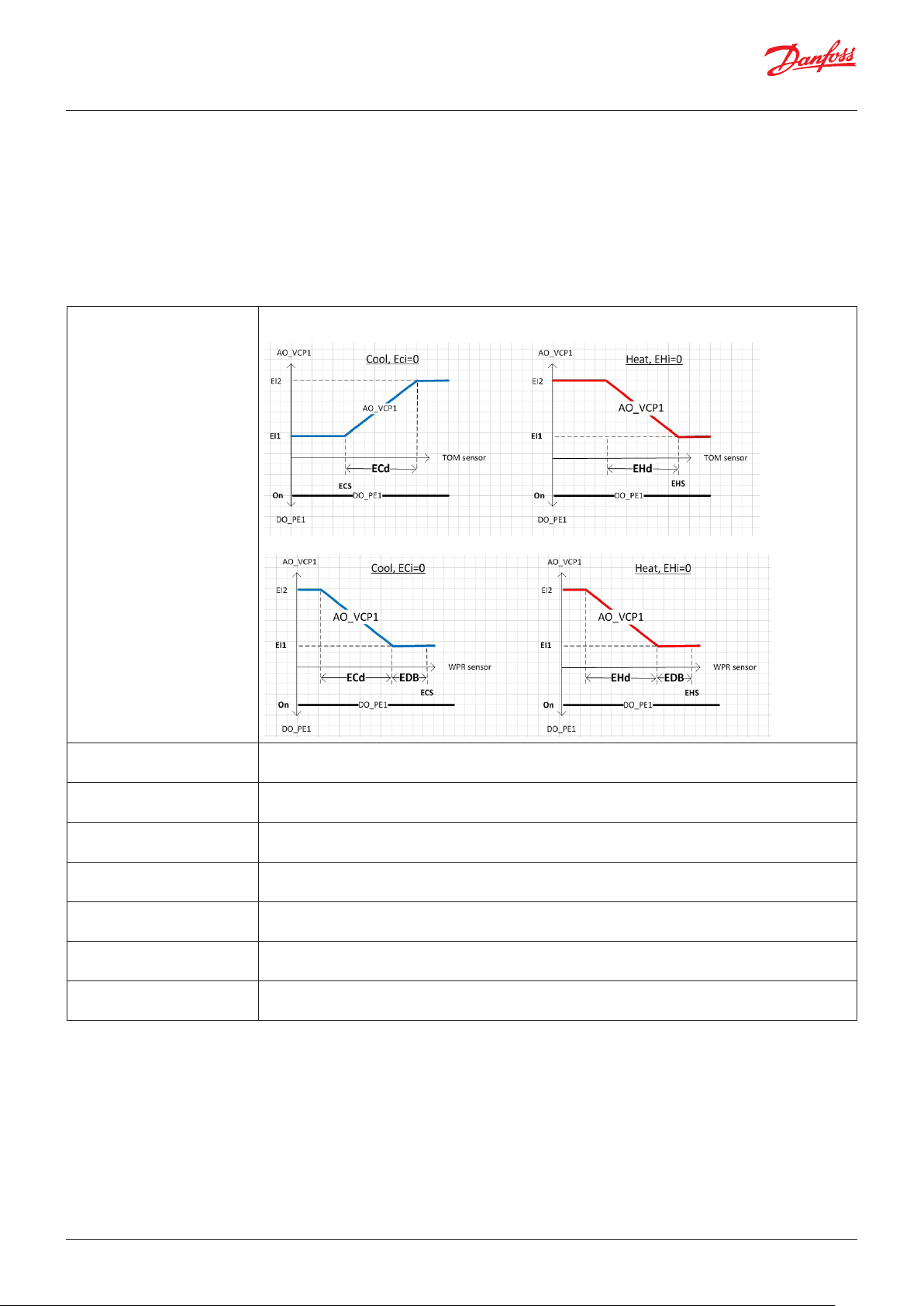
User Guide | Chiller and reversable chiller, reciprocating, scroll and screw compressors
Modulating Pump
Parameter: ERT, ECS, ECd, ECi, EHS, EHd, EHi, EDB, EI1, EI2, EI3
Functionalities: Enable evaporator variable capacity pump
Analogue input: TOM, WPR
Analogue output: VCP1, VCP2
Digital output: PE1, PE2
Note: works for P01=ON
ERT-Regulation type 0= TOM: The speed of the pump is defined through the sensor TOM (Tout evap mix)
Note: in case of sensor fault is used the sensor TO1,
1= WPR: The speed of the pump is defined through the sensor WPR (Water pressure)
ECS-Cooling setpoint It's in °C (or barG for ERT=WPR)
Note: Check ERT
ECd-Cooling differential It's in °C (or barG for ERT=WPR)
Note: Check ERT
ECi-Cooling integral time It's in °C (or barG for ERT=WPR)
Note: Check ERT
EHS-Heating setpoint It's in °C (or barG for ERT=WPR)
Note: Check ERT
EHd-Heating differential It's in °C (or barG for ERT=WPR)
Note: Check ERT
EHi-Heating integral time It's in °C (or barG for ERT=WPR)
Note: Check ERT
EDB-Dead band It's in °C (or barG for ERT=WPR)
Note: Check ERT
52 | BC295150867120en-000201 © Danfoss | DCS (vt) | 2019.08
Page 53

User Guide | Chiller and reversable chiller, reciprocating, scroll and screw compressors
EI0-Inverter enable 0=NO means that the pump’s variable speed control is disabled
1=YES means that the pump’s variable speed control is enabled
EI1-Minimum speed It’s in %
Defines the minimum speed of the pump
EI2-Maximum speed It’s in %
Defines the maximum speed of the pump
EI3-Max pump speed up time
at startup
It’s in seconds
Defines how long the pump holds the maximum speed during startup
Fan for the internal coil
Parameter: P21, P22, P50
For (H3=Air), (H1<3), (H4<3):
The evaporator fan is driven on the basis of the pressure that is inside
the internal coil. If the fans are shared between the evaporators
(H12=yes) the pressure used is the worst one of the 2 circuits.
Note: if there are 2 evaporators which are separated, the outputs PE2
and EI2 will work for evaporator 2
Functionalities: Enable evaporator variable capacity pump
Functionalities: Enable step management for evaporator fans
Digital output: PE1, PE2
Digital input: OPE1, OPE1
Analogue input: low pressure or high pressure
Analogue output: E1, E2
Alarms: AP1, AP2
________________________________________
Second pump (internal coil):
Managing another pump is only possible for circuit 1, as defined by
parameter P21
Digital input: OPE2
Digital output: PE2
P21-Pumps rotation type 0= bUP: Emergency mode: If the pump overload alarm A05 or flow switch alarm A03 is active, the
second pump will replace the pump running; the A08 warning is generated. If the alarm goes back
the A08 warning is reset.
1= Strt: Emergency mode more rotation to each restart (It also works for P01>1 ).
2= HOUr: Emergency mode more rotation when the gap of the working hours is bigger that P22
P22-Max run hours to force
rotation
P50-Maximum limit It’s in Hours*1000
It’s in Hours
Used with P21=HOUr, defines the hours gap above which the pumps are rotated
If the pump works more than P50 hours * 1000 , the warning A10 (or A11) is generated
© Danfoss | DCS (vt) | 2019.08 BC295150867120en-000201 | 53
Page 54

User Guide | Chiller and reversable chiller, reciprocating, scroll and screw compressors
Free cooling
Parameter: FrA, Fr1, Fr2, Fr3, Fr4, Fr5, Fr6, Fr7, Fr8, Fr9, FI1, FI2, FI3
The free cooling regulation uses the favourable conditions of
outside air temperature to contribute to cooling the water. It uses an
additional coil (free cooling coil) enabled through the free cooling
valve which deflecting the return water from the plant if the outside
air temperature conditions are favourable.
Note: Free cooling management is active only in air/water units in
cooling mode.
Note: In case of multiple evaporators and condensers, the free
cooling is handled only on the first evaporator and condenser.
Functionalities: Enable free cooling capacity
Digital output: FV1, FRC
Digital input: OH1, OH2, OH3, OH4, OHL1, OHL2, OHL3, OH4, OH
Analogue input: TFC, TOUt
Analogue output: FV1, FRC, FC1
Alarms: A7Z, AFC, FRC
Fr0- Free cooling enable
and probe
Fr1- Delta Free-cooling It's in Kelvin
Fr2- Only Free-cooling
setpoint
FrA- Only free cooling delta It’s in Kelvin
Fr3- Only free cooling delay It’s in seconds
0=No means that the free cooling is disabled
1=Tin means that the free cooling regulation probe is TIN_Tin Evaporator
2=Tout means that the free cooling regulation probe is TO1_Tout Evaporator1
Defines the minimum temperature gap between TFC_Free Cooling Temp and the TOUt_Tout to en-
able the free cooling logic.
Note: free cooling is disabled when:
• The water circulation pump is not operating
• There is not a minimum temperature gap between TFC_Free Cooling Temp and the TOUt_Tout
(<(Fr1- 1.5°C))
• One of the following alarms has occurred: antifreeze alarm, serious alarm from digital input, pump
overload alarm, evaporator flow alarm, fault of regulation probe, anti-freeze probe, free-cooling
probe, outside temperature probe
It’s in °C
If the outside temperature (TOUt_Tout) stays below Fr2 for more than Fr3 seconds the compressors
are switched off.
Note: check parameter FrA
If the outside temperature (TOUt_Tout) is above (Fr2+FrA) the compressors are allowed to work.
Note: check parameter Fr2
Note: check parameter Fr2
54 | BC295150867120en-000201 © Danfoss | DCS (vt) | 2019.08
Page 55
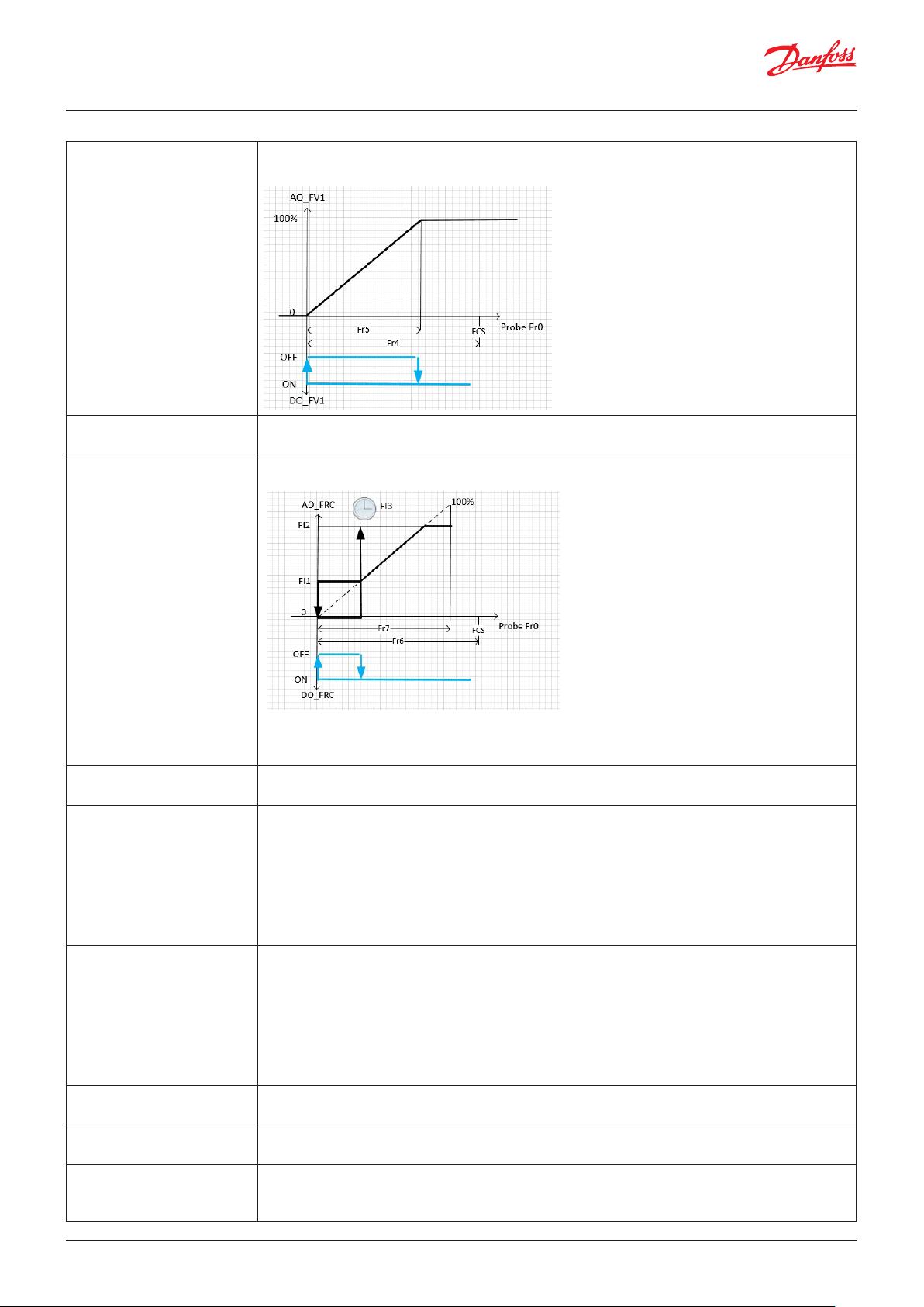
User Guide | Chiller and reversable chiller, reciprocating, scroll and screw compressors
Fr4- Offset free cooling valve It’s in °C
Defines the opening point of the free cooling valve (FV1 Free Cooling Valve)
Fr5- Differential free
cooling valve
Fr6- Offset free cooling fan It’s in °C
Fr7- Differential free cooling
fan
Fr8- AntiFreeze temp It’s in °C
Fr9- Free cooling/Cond priority 0=Cond means that in case of free-cooling and condensation that are working together the ana-
FI1- Minimum speed It’s in %
FI2- Maximum speed It’s in %
FI3- Max fan speed up time
at start up
It’s in °C
Note: see the image in parameter Fr4
Defines the fan starting point related to the free-cooling request.
Note: The analogue output FRC_Free Cooling Fan is managed as in the image above;
Note: For the analogue output FC1_Inverter Fan Cond 1 check parameter Fr9_ Free cooling/Cond
priority
It’s in °C
Note: check picture in the parameter Fr6
If the outside air temperature TOUt_Tout is below Fr8 °C
• the alarm AFC_Free cooling ice alarm is generated,
• the main circulation pump is turned on and the free cooling valve is operated as follows:
– when the unit is OFF, it is open at 100% of its capacity
– when the unit is ON, it is open at 10% of its capacity
– The ON/OFF type valve is always open at 100%.
Note: The procedure stops with a fixed hysteresis of 1K.
logue output FC1_Inverter Fan Cond 1 follows the control of gas condensation
1= FrEE means that in case of free-cooling and condensation that working together the analogue
output FC1_Inverter Fan Cond 1 follows the free cooling request
2=GrEA means that where free cooling and condensation are working together, the analogue output
FC1_Inverter Fan Cond 1 uses the greatest value
3=Ind means that the analogue output FC1_Inverter Fan Cond 1 follows only the gas condensation
and the analogue output FRC_Free Cooling Fan follows the free-cooling request
Defines the minimum speed of the free cooling fan FRC_Free Cooling Fan
Defines the maximum speed of the free cooling fan FRC_Free Cooling Fan
It’s in seconds
Defines the time that the FRC_Free Cooling Fan stays at the maximum speed during the cut in, after
that, it will follow the free-cooling request
© Danfoss | DCS (vt) | 2019.08 BC295150867120en-000201 | 55
Page 56

User Guide | Chiller and reversable chiller, reciprocating, scroll and screw compressors
Valve in the water line
Parameter: EF1, EF2
This valve will close the water line when the chiller is switched off
Functionalities: Enable water valve
Digital output: EFV, PE1
EF1- Delay pump on from
valve
EF2- Delay valve close from
pump off
It’s in seconds
The valve EFV_Evaporator Pump Flow Valve is open when the chiller is switched on, EF1 seconds
after the pump is allowed to work
It’s in seconds
The valve EFV_Evaporator Pump Flow Valve will switched off EF1 seconds after a pump is cut off
External coil
Parameter: F01
Digital output: FC1, …, FC12, FI1, FI2, FI3, FI14,
Digital input: OFC, FCL1. FCL2, FCL3, FCL4, OFC1, …, OFC12
Analogue input: dP1, dP2, dP3, dP4, SP1, SP2, SP3, SP4
Analogue output: FC1, FC2, FC3, FC4, DF1, …, DF12
Alarms: AF1, …, AF12, A50, A51, A52, A53, A54
F01-Condensation regulation
type
0=OFF means that the fans will not be managed
1= ON means that the fans are always ON. They are switched OFF only when the unit is OFF;
this setting does not work for the analogue output
2=ON_C means that if the circuit is operating, the relative fans are switched on.
The fans will be switched off F03 seconds after the cut off of the last compressor in the circuit.
3=Prb means that the fans are managed in relation to the pressure inside the external coil: Note:
check parameters H42, ex2 and F10
4=Ft0 means that the fans are regulated at 2 fixed speeds based on the external temperature.
If Tout<F22, speed is set to F20. If Tout>F22+F23, speed is set to
F21
Note: it works only with F10=yes
5=TcP means that the fans are managed like F01=Prb but the adjustment (parameters FCs, FCd, …)
of the parameters has to be in temperature; the software will translate pressure into temperature
(check parameter o30)
56 | BC295150867120en-000201 © Danfoss | DCS (vt) | 2019.08
Page 57

User Guide | Chiller and reversable chiller, reciprocating, scroll and screw compressors
Fan requests
Parameter: F02, F03, FC, FCD, FCI, FCd, FHS, FHD, FHI, FHd
The request by the fan is calculated with PID logic. This request can be used with a
stepless fan or spread to ON-OFF fans.
Below is one example of how the fan request is managed in both the cases
Note: it works for F01=Prb or TcP
F11=YES
F10=YES
© Danfoss | DCS (vt) | 2019.08 BC295150867120en-000201 | 57
Page 58

User Guide | Chiller and reversable chiller, reciprocating, scroll and screw compressors
F02- Fan off with compressor
OFF
F03- Pump/Fan OFF delay
from compressor OFF
FCS-Cooling setpoint It’s in barG or °C (F01=TcP)
FCD-Cooling differential It’s in barG or °C (F01=TcP)
FCI-Cooling integral time It’s in seconds
FCd-Cooling derivate time It’s in seconds
FHS-Heating setpoint It’s in barG or °C (F01=TcP)
FHD-Heating differential It’s in barG or °C (F01=TcP)
FHI-Heating integral time It’s in seconds
FHd-Heating derivate time It’s in seconds
0=NO
1=YES means that the fan is allowed to work only if the relative circuit is switched on
Note: it works only for F01=3
It’s in seconds
After the circuit cut off, the fan/pump is kept active for F03 additional seconds
This is the setpoint used for the PID control of the fan in chiller mode.
Note: works for F01=Prb
This is the proportional band of the fan’s PID control in chiller mode.
Note: works for F01=Prb
This is the integral part of the fan’s PID control in chiller mode.
Note: works for F01=Prb
This is the derivate part of the fan’s PID control in chiller mode.
Note: works for F01=Prb
This is the setpoint used for the PID control of the fan in heat pump mode.
Note: works for F01=Prb
This the proportional band of the fan’s PID control in heat pump mode.
Note: works for F01=Prb
This is the integral part of the fan’s PID control in heat pump mode.
Note: works for F01=Prb
This is the derivate part of the fan’s PID control in heat pump mode.
Note: works for F01=Prb
58 | BC295150867120en-000201 © Danfoss | DCS (vt) | 2019.08
Page 59
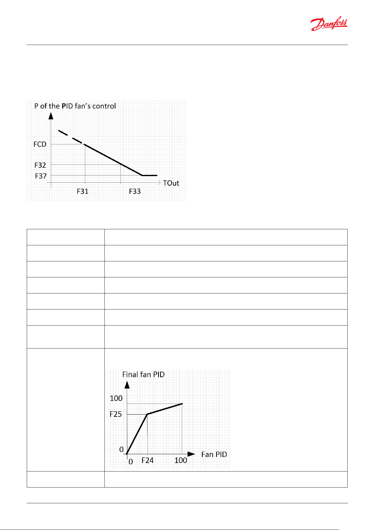
User Guide | Chiller and reversable chiller, reciprocating, scroll and screw compressors
Fan regulation with a variable proportional part
Parameter: F31, F32, F33, F34, F35, F36, F37, F24, F25
The proportional part (FCD or FHD) of the PID regulation for the
fan control can be changed linearly:
Functionalities: Enable advanced condenser regulation
Analogue input: Tout
F31- Cooling base out
temperature
F32- Cooling second diff ref Check picture above
F33- Cooling second out
temp ref
F34- Heating base out
temperature
F35- Heating second diff ref Check picture above
F36- Heating second out
temp ref
F37- Differential minimum
value
F24-Shaping X component It’s in %
Check picture above
Note: works in cooling mode
Note: works in cooling mode
Check picture above
Note: works in cooling mode
Check picture above
Note: works in heating mode
Note: works in heating mode
Check picture above
Note: works in heating mode
It’s in barG or °C (F01=TcP)
Defines the minimum value allowed for the proportional band.
Note: Check picture above
The parameters F24 and F25 define the shape of the PID output of the fan.
The image shows the tuning of the fan PID
F25-Shaping Y component It’s in %
Check Parameter F24
© Danfoss | DCS (vt) | 2019.08 BC295150867120en-000201 | 59
Page 60

User Guide | Chiller and reversable chiller, reciprocating, scroll and screw compressors
Economic setpoint for fan regulation
Parameter: SS1, SS2, SS3, SS4
Digital input: CSE1, CSE2, CSE3, CSE4
SS1-Second set point enable 0=NO
1=YES means that when the digital input CSEx is closed, the “x” external coil gets a new setpoint (SS2
for cool mode and SS3 for heat mode)
SS2-Cooling Second set point It's in barG or °C (F01=TcP)
Note: Check SS1
SS3-Heating Second set point It's in barG or °C (F01=TcP)
Note: Check SS1
SS4- Second set auto dec It's in barG or °C (F01=TcP)
When a compressor is at minimum power, the second setpoint becomes (SS2-SS4) or (SS3-SS4)
Note: works only for screw compressor
Stepless regulation of the fan
Parameter: F10, F11, F12, F13, F14, F20, F21, F22, F23
Note: the pictures above are related to proportional regulation
Note: it works for F01=Prb
Digital output: FI1, FI2, FI3, FI14
Digital input: OFC, FCL1. FCL2, FCL3, FCL4
Analogue input: dP1, dP2, dP3, dP4, SP1, SP2, SP3, SP4
Analogue output: FC1, FC2, FC3, FC4,
Alarms: AF1, …, AF12, A50, A51, A52, A53, A54
F10- Inverter enable 0=NO
1=YES means that the analogue outputs Fcx are managed
F11- Minimum speed It’s in %
Defines the minimum speed of the fan InverterFanCondx (external coil)
Note: see image above
F12- Maximum speed It’s in %
Defines the maximum speed of the fan InverterFanCondx (external coil)
Note: see image above
F14- Max fan speed up time at
start up
It’s in seconds
Defines the time that the InverterFanCondx stays at the maximum speed during the cut in. After
that, it will follow the fan’s request
Note: see image above
60 | BC295150867120en-000201 © Danfoss | DCS (vt) | 2019.08
Page 61

User Guide | Chiller and reversable chiller, reciprocating, scroll and screw compressors
F20-Fixed speed low It’s in %
If the external temperature (AO_Tout) goes below F22, the InverterFanCondx is set to F20%
If the circuit is switched off the AO_ InverterFanCondx is set to 0%
Note: It works only for F01= Fto
Note: there are no differences between either machine mode (heating or cooling)
F21-Fixed speed high It’s in %
If the external temperature (AO_Tout) goes above F22+F23 , the InverterFanCondx is set to F21 %
Note: It works only for F01= Fto
Note: there are no differences between either machine mode (heating or cooling)
F22-Tout limit It’s in °C
Check parameter F20
F23-Tout hysteresis It’s in °C
Check parameter F21
Hot gas bypass valve
Parameter: Bp0, Bp1
Digital output: FC1, FC2, FC3, FC4
Analogue input: dP1, dP2, dP3, dP4, SP1, SP2, SP3, SP4
Bp0-Pressure set point It’s in barG
It is related to the external coil’s pressure
Defines the pressure threshold above which the DO_FCx is closed
Note: Check parameter Bp1
Bp1-pressure differential It’s in barG
It is related to the external coil’s pressure
If the pressure goes below (Bp0-Bp1) the output DO_FCx is opened
© Danfoss | DCS (vt) | 2019.08 BC295150867120en-000201 | 61
Page 62
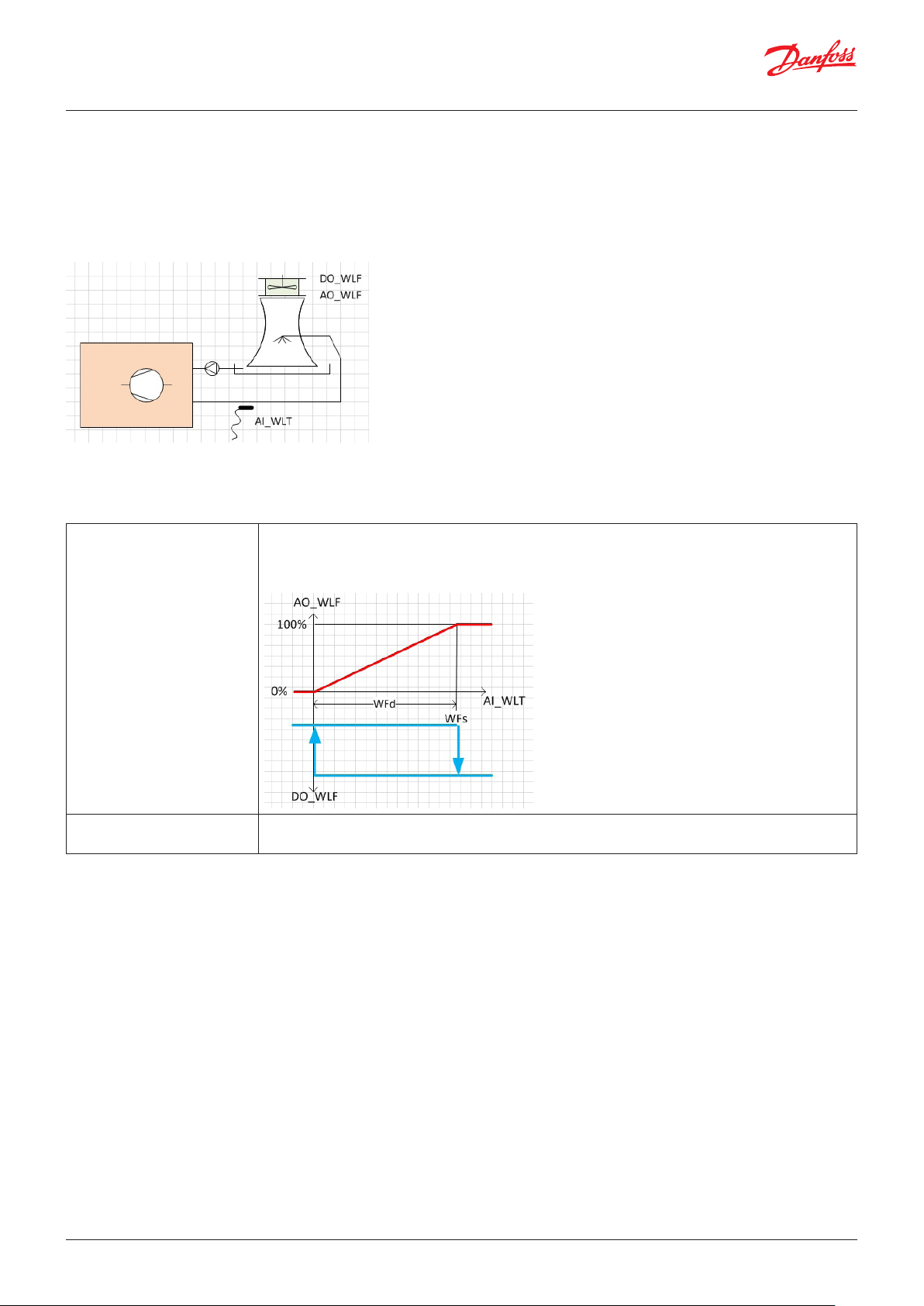
User Guide | Chiller and reversable chiller, reciprocating, scroll and screw compressors
Cooling towers
Parameter: WFs, WFd
The cooling tower works in order to keep the temperature WLT
below a WFs threshold ;
Note: The cooling tower works only if the chiller’s condenser
fan/ pump is working (DO_ FC1)
Functionalities: Enable water loop pump management
Digital output: WLF, FC1
Analogue input: WLF
Analogue output: WLF
WFs-Water fan setpoint It's in °C
The cooling tower is managed based on the water temperature WLT.
The cooling tower linearly increases the analogue output AO_WLF between WFs-WFd and WFs °C ,
as shown in the image below
WFd-Water fan differential It’s in °C
Note: check parameter WFs
62 | BC295150867120en-000201 © Danfoss | DCS (vt) | 2019.08
Page 63

User Guide | Chiller and reversable chiller, reciprocating, scroll and screw compressors
Reversing cycle valve (4 ways valve)
Parameter: rE2, rE1, rE3, rE4
The working mode of the chiller is defined by parameter rE2.
The reversing cycle valve will switch with rE1 seconds of delay
from the cut off of the last compressor running
Functionalities: Enable Heat Pump Control
Digital input: HC
Digital output: HC1, HC2, HC3, HC4
Analogue input: Tout
rE2-Changeover from 0=DI means that the working mode is defined by Digital Input HC
1=UI means that the working mode is defined by parameter y03 and the digital input HC. The
mismatch between the 2 ways to set the working mode is solved considering that the last request
(from DI or from UI) will win. If the DI does not match the working mode, the DI will start to work only
after being passed through the actual status
2=Tout means that the working mode is defined by the probe Tout (check parameters rE3 and rE4)
rE1-Change over delay It's in seconds
rE1=0 means that the compressors are not switched off for switching the 4 way valve
rE1<>0 means that the working mode is changed following 3 steps:
• Switch off all the running compressors
• After rE1 seconds, the 4-way valve is switched
• After rE1 seconds the compressors are enabled to work
rE3-Changeover setpoint It’s in °C
If the outside temperature (AI_Tout) goes below rE3 °C the working mode becomes heating
Note: works only if rE2=2
rE4-Changeover differential It’s in °C
If the outside temperature (AI_Tout) goes above rE3+ rE4 °C the working mode becomes cooling
Note: works only if rE2=2
© Danfoss | DCS (vt) | 2019.08 BC295150867120en-000201 | 63
Page 64
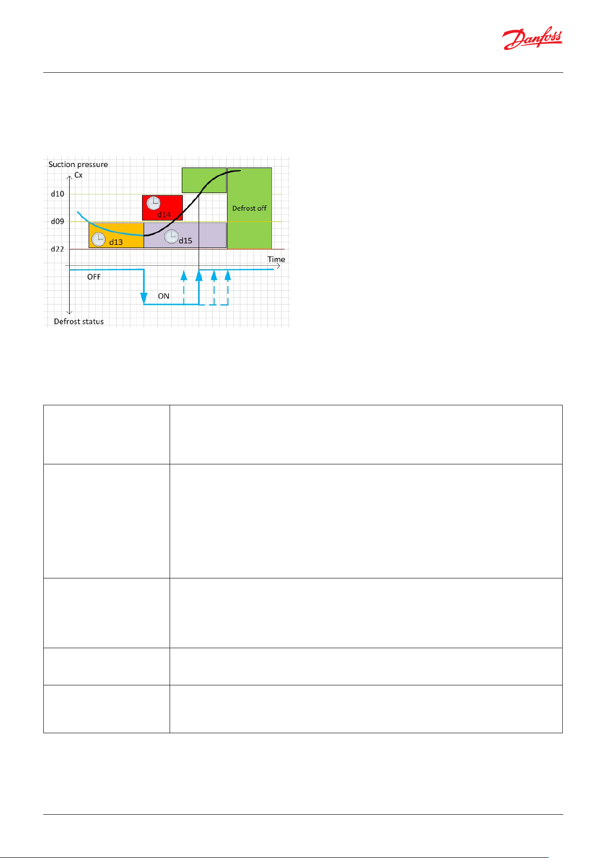
User Guide | Chiller and reversable chiller, reciprocating, scroll and screw compressors
Defrost
Parameter: d01, d02, d03, d04, d05, d06, d07, d09, d10, d11, d12, d13, d14, d15, d16, d20, d22, d23, d25, d26
The circuit suction pressure detects the condition to defrost the circuit;
Functionalities: Enable Heat Pump Control
Digital input: DEF
Digital output: H1, H2, H3,H4
Analogue input: dP1, dP2, dP3, dP4, SP1, SP2, SP3, SP4, Tout, TD1, TD2, TD3,TD4
Warning: A13
d01-Defrost enable 0=NO: disable
1=All: means that the defrost is performed across circuits at once when at least one circuit
requires defrosting
2=Ind: means that the defrost is performed only in the circuits which have to be defrosted and the
other circuits are switched off
d02-Defrost type 0=SpEp: means that the defrost is detected and stopped in relation to the probe SPx
(see parameters d09-d10)
1=SpEt: means that the defrost is detected in relation to the probe SPx and the defrost is stopped
only after d15 minutes (Defrost maximum time)
2=StEt: means that the defrost is detected and stopped in relation to the probe TDx (see parameters
d11 and d12)
3=StEM: means that the defrost is detected in relation to the probe TDx and the defrost is stopped
only after d15 minutes
4=Comb: the defrost is performed as d02=SpEp but the procedure to start defrosting will work only
if the AI_TCDx < d11, the procedure to end the defrosting will work only if the AI_TCDx > d12
d03-Defrost digital input
config
d04-Heaters ON while
defrosting
d05-Fan management while
defrosting
0=NO: Digital input DEF does not work
1=Strt: If the DI_DEF is closed, the defrost is performed ( d16 can delay the start)
2=End: If the DI_DEF is opened, the defrost is stopped; If the DI_DEF is closed, the defrost starts or
stops according to the manner selected with d02
3= StEn: The digital input is used to start defrosting (when toggled from closed to open) and to stop
defrosting (when toggled from open to closed)
0=NO:
1=Strt: This means that the heaters are switched on during defrosting (in order to reduce the cold
effect of the defrosting action)
0=OFF: It means that during defrosting and the dripping phase the fan is switched off
1=EqUA: It means that during defrosting the fan works in cooling mode
1=ONdr: It means that during defrosting the fans are switched off and during the dripping phase the
fan is switched on 100%
64 | BC295150867120en-000201 © Danfoss | DCS (vt) | 2019.08
Page 65

User Guide | Chiller and reversable chiller, reciprocating, scroll and screw compressors
d06-Fan only defrosting It’s in °C
0: It means that this function is disabled
>0: It means that the defrost is only performed with the fan when the external temperature is
Tout>d06; in this case, when defrosting is detected the compressors are switched OFF and the fan is
set to 100%.
Note: the start and stop conditions and the support heaters management stay unchanged
d07-Enable LowP alarm in
defrost
d09-Defrost start setpoint It’s in bar G
d10-Defrost stop setpoint It’s in bar G
d11-Combined defrost temp
start setpoint
d12-Combined defrost temp
stop setpoint
d13-Defrost temp start
verifying time
d14-Defrost minimum time It’s in sec
d15-Defrost maximum time It’s in minutes
d16-Minimum time to defrost
same circuit
d20-Waiting time after
defrosting
0=NO:
1=Yes
If the pressure dPx stays below d09 for more than d13 seconds, defrosting is detected
Note: works for d02=0, d02=1 and d02=4
If the pressure dPx goes above d10 defrosting is completed
Note: it works for d02=0 and d02=4
It’s in °C
If the temperature TCDx stays below d11 for more than d13 seconds, defrosting is detected
Note: it works for d02=2, d02=3 and d02=4
It’s in °C
If the temperature TCDx goes above d12 defrosting is completed
Note: it works for d02=2 and d02=4
It’s in seconds
Check parameters d09 and d11
Counting is stopped but not reset when the temperature/pressure goes beyond that limit d11/d09.
Counter is reset at power ON or when the defrost cycle starts.
Defrosting can be switched off only after d14 seconds.
This represents the maximum duration for defrosting beyond which defrosting is stopped and the
A13 warning occurs. This warning is reset after a correct defrost cycle.
Note: If d02=1, parameter d15 defines the duration of defrosting.
It’s in minutes
Defines the minimum wait time to defrost the same circuit
Note: Ignored if the request to defrost comes from a digital input
It’s in seconds
Defines the dripping time after the coil is defrosted: also check parameter d25
d21-Start verifying time It’s in seconds
Used to force defrosting to start
If the pressure is maintained for d21 seconds below d22 the defrost will start
d22-Start setpoint It’s in bar
Used to force defrosting to start
If the pressure is maintained for d21 seconds below d22 the defrost will start
d23-Compressor power in
defrost
d25-Force compressor ON
during dripping
© Danfoss | DCS (vt) | 2019.08 BC295150867120en-000201 | 65
It’s in °C
Defines the circuit power to be used during defrosting
0=NO:
1=Yes: This means that the compressor is kept running during the dripping phase
Page 66
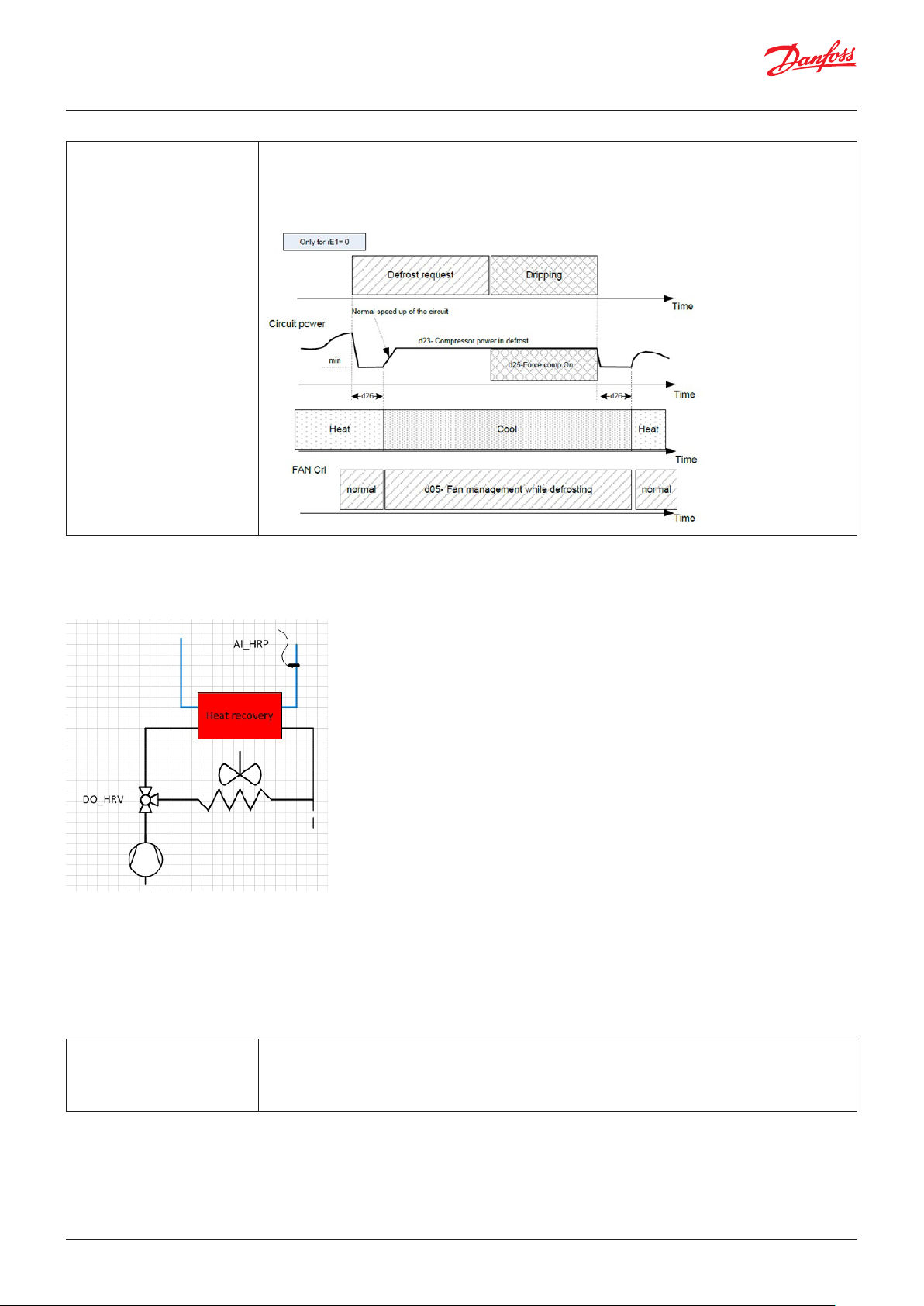
User Guide | Chiller and reversable chiller, reciprocating, scroll and screw compressors
d26-Waiting time for reducing It’s in seconds
It works only with rE1=0 and for stepless screw compressors.
When defrosting is detected, the compressor is set to the minimum (the decrement valve is held open)
starting from the detection of defrosting we wait d26 seconds before going into cooling mode;
After dripping we do the same;
Heat recovery
Parameter: HRs, HRm, HRc, HRn, HRt, HRo
Functionalities: Enable heat recovery management
Digital input: HRE, HRD
Digital output: HRV
Analogue input: HRP
Alarm: A9A
Note: sensor A9A’s alarm will switch off the heat recovery after
HRc seconds
HRs-Heat Recovery Set It’s in °C
If the temperature HRP goes below HRs °C, the digital output HRV is closed
Note: if the digital input HRE= close the digital output HRV is closed too
Note: if the parameter HRn=0 or DI_HRD=Close the heat recovery is disabled
66 | BC295150867120en-000201 © Danfoss | DCS (vt) | 2019.08
Page 67
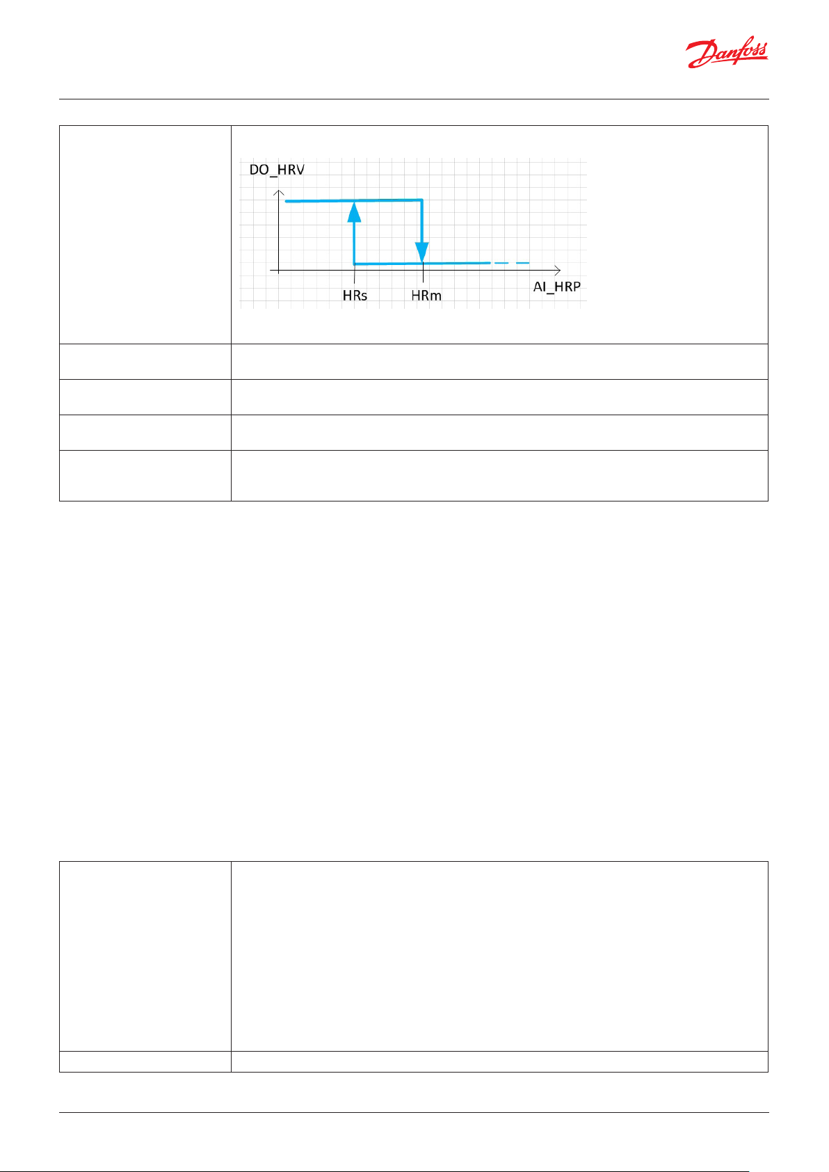
User Guide | Chiller and reversable chiller, reciprocating, scroll and screw compressors
HRm-Heat Recovery Max
temperature
HRc-Heat Recovery Cut Out
Delay
HRn-Heat Recovery Max Cycles per Hours
HRt-Heat Recovery fan off 0=NO: this means that there are not changes in the fan management
HRo-Heat Recovery Cond set
Offset
It’s in °C
If the temperature HRP goes above HRm °C, the digital output HRV opens after HRc seconds
Note: If the temperature HRP goes above HRm °C, the fan can work immediately
It’s in seconds
Check parameter HRm
HRn=0: this means that this function is disabled
HRn>0: Defines the maximum number of times that recovery can start per hour
1=Yes: This means that the fan is switched off if the heat recovery is working
It's in bar
When the heat recovery is working, the fan’s setpoint is increased by HRo bar ;
Note: it works only in cooling mode
Superheat
Parameter: V10, V20, bAt, ex1, ex2, ex3, N19, N04, N05, N20, N22, N10, N09, N11, N32, N18, N17, N15, N21, SHO
The software manages a number of valves equal to the number of
circuits (H1 * H2).
Are available internal valves driver (for MCX152V or MCX061V) or the
connection trough CANBUS with the Danfoss EXD/EKE 1C driver.
Note: the superheat algorithm is the same for EXD and MCX.
Functionalities: Enable EEV using EKE 1C
Enable MMI navigation
Functionalities: Enable EEV using EXD 316
Functionalities: Enable EEV using MCX driver
Analogue input: SP1, sT1, SP2, St2
Analogue output: SH1, SH2
Alarms: E10, …, E49
Note: inputs and outputs are related to the internal valves
v10-Valve 1 type 0=ETS 25
1= ETS 50
2= ETS 100
3= ETS 250
4= ETS 400
5=Custom
6=UKV
7=ETS Colibri
Note: this only works for MCXxxV.
Defines the type of valve that will be used.
With v10 =5, the valve’s drive setting is configured by editing the file CustomValveParameters.c “inside
the BIN/IOUtils folder.
v20-Valve 2 type Check parameter v10
© Danfoss | DCS (vt) | 2019.08 BC295150867120en-000201 | 67
Page 68

User Guide | Chiller and reversable chiller, reciprocating, scroll and screw compressors
bAt-Enable battery check 0=No
1= Yes: if the voltage of the battery goes below 12 V, alarm E18 EEV1 battery low is generated
Note: this only works for MCXxxV,
ex1-First EEV add. Offset ex1= 0: the EXD/EKE drivers are not managed
ex1<> 0: Defines the CANBUS address of the first EXD/EKE driver; the CAN address of the other
drivers, if any, must be consecutive to the first and without gaps.
Note: Refer to the specific document on how to set the CAN address on the EXD/EKE drivers; we
suggest setting ex1 to 20 as it is the default address of the EXD drivers.
ex2-Define suction pressure
source
ex3-Number of EEV per circuit ex3=1 means that there is 1 valve per circuit
N19-Damping of amplification
factor N04
N04-P Amplification factor Kp If the Kp value is reduced the regulation becomes slower.
N05-Integration time Tn If the Tn value is increased the regulation becomes slower.
N20-Amplification factor for
the SH
N22-Min superheat ref per
load under 10%
N10-Min superheat ref Warning! Due to the risk of liquid flow the setting should not be lower than approx. 2-4 K.
N09-Max superheat ref
N11-MOP point in press
(bar G)
N32-Max valve opening
degree
N18-Stability factor for
superheat control
N17-Signal safety during
start-up
N15-Start-up time for safety
signal
N21-Definition of superheat
control mode
SHO-Superheat output type 0=SM: Superheat control is performed over MCX Stepper Motor
0=MCX means that evaporator pressure is read from an MCX analogue input
1= EEV means that evaporator pressure is read through CANBUS, from the analogue input of the EXD
Note: check parameter H42
ex3=2 means that there are 2 valves per circuit
Note: in case of ex3=2 and ex2=1 the suction pressure is read from the first driver
Note: ex3=2 works only with EXD drivers, in case of 2 circuits the first 2 drivers are in the circuit 1
This setting damps the normal amplification Kp, but only just around the reference value. A setting of
0.5 will reduce the KP value by half.
The value should only be changed by specially trained staff.
This setting determines the valve’s opening degree as a function of the change in evaporating
pressure. An increase of the evaporating pressure will result in a reduced degree of opening. When
there is a drop in the low-pressure thermostat during startup, the value must be raised a bit. If there
is pendling during startup, the value must be reduced a little.
The value should only be changed by specially trained staff.
The value must be smaller than “N10”
Measured in bar G
The valve’s opening degree can be limited. The value is set in %
A higher value will allow the control function a greater fluctuation of superheat before the reference
is changed. The value should only be changed by specially trained staff.
The control function uses the value as start value for the valve’s opening degree at each thermostat
cut-in. The controller continuously calculates new values by adaptive control.
The value should only be changed by specially trained staff.
If the controller does not obtain a reliable signal within this period of time, the controller will try to
establish a stable signal in other ways. (Too high a value may result in a flooded evaporator).
The value should only be changed by specially trained staff.
N21=0: the superheat reserence is N10
N21=1: Lowest permissible superheat (MSS). Adaptive regulation.
N21=2: Load-defined superheat. The reference is established based on the line formed by the three
points: N09, N10 and N22.
1=AO: Superheat control is performed over MCX Analogue Output
2=Inr: inner loop regulation and S4 temperature less T0 (double loop)
Note: the parameters N19,...,SHO work only for MCXxxV.
68 | BC295150867120en-000201 © Danfoss | DCS (vt) | 2019.08
Page 69
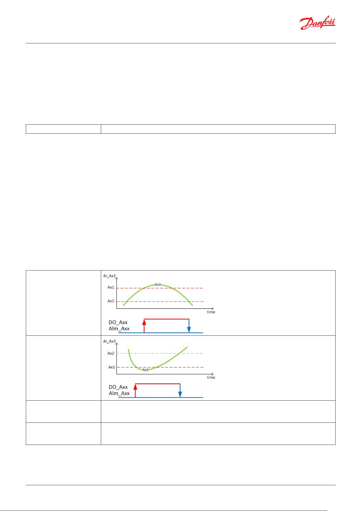
User Guide | Chiller and reversable chiller, reciprocating, scroll and screw compressors
Input output expansion module
Parameter: XCn
It is possible to use only one additional MCX as IO expansion
module, the connection is through CANBUS.
The MCX when is not programmed (as it is out of the box) is ready to
be used as expansion module.
By adjusting parameter XCn the software is ready to get connection
Alarms: Cn
XCn-Expansion can address The software looks for input output expansion module on the CANBUS address XCn
Auxiliary alarms
Parameter: a11, a21, a31, a41, a12, a22, a32, a42, a13, a23, a33, a43, a 14, a24, a34, a44
Functionalities:
• Enable auxiliary alarms from analogue input
• Hide auxiliary alarms notification, enabled only the Digital Outputs
Analogue input: Ax1, Ax2, Ax3, Ax4
Digital input: All
Digital output: Ax1, Ax2, Ax3, Ax4
Alarms : Ax1, Ax2, Ax3, Ax4
Note: the action of the alarm has to be defined in the alarm tab
Note: with the “Disable the alarm of the auxiliary alarms” functionality it
is possible to disable the alarms but keep the action of the alarms
a11,a21, a31, a41- Aux alarm
x cut-in
a12, a22, a32, a42- Aux alarm
x cut-out
a13, a23, a33, a43- Aux alarm
x AI selection
a14, a24, a34, a44- Aux alarm
x DI selection
Defines the analogue input to detect the auxiliary alarm.
a13=SPP means analogue input ax1
a13=AI1 means analogue input 1
Defines the digital input to detect the auxiliary alarm.
a14=SPP means digital input AX1
a13=AI1 means analogue input 1
© Danfoss | DCS (vt) | 2019.08 BC295150867120en-000201 | 69
Page 70
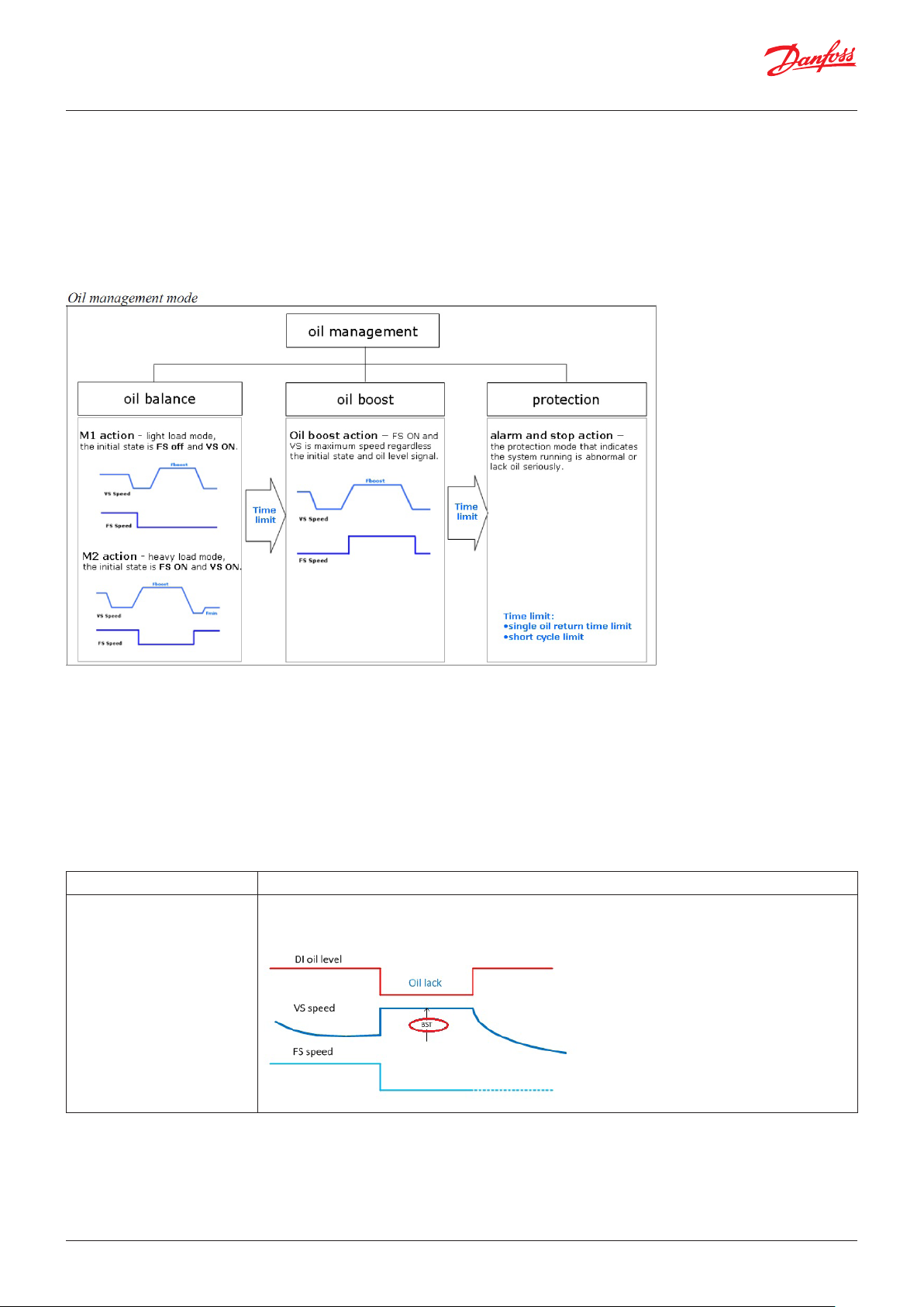
User Guide | Chiller and reversable chiller, reciprocating, scroll and screw compressors
Oil Alarm Tandem
Parameter: BME, BST, TD1, TD2, TD3, TD4, ADO, BOF, BFR
- Scenarios: On-OFF and variable speed (VS) Danfoss tandem
compressors
- Purpose: recover oil from ON-OFF compressor (Balancing mode) or
from the pipes line (Boost mode)
- During the Balance action the ‘BAW_Balance Action Warning’
warning is turned on
- During the Boost action the ‘BOW_Boost Action Warning’ warning
is turned on
Functionalities: Enable Oil Alarm Tandem Control
Digital input: LEV
Digital output: C1, C2
Analogue output: C1
Alarms: OLA, BAW, WBW, BOW, OPA
OME-Oil Manager Enable OME=Yes means that the logic is enabled
BST-Boost action speed Defines the speed of the inverter compressor during the logic in balance and boost action,
in both the cases
70 | BC295150867120en-000201 © Danfoss | DCS (vt) | 2019.08
Page 71
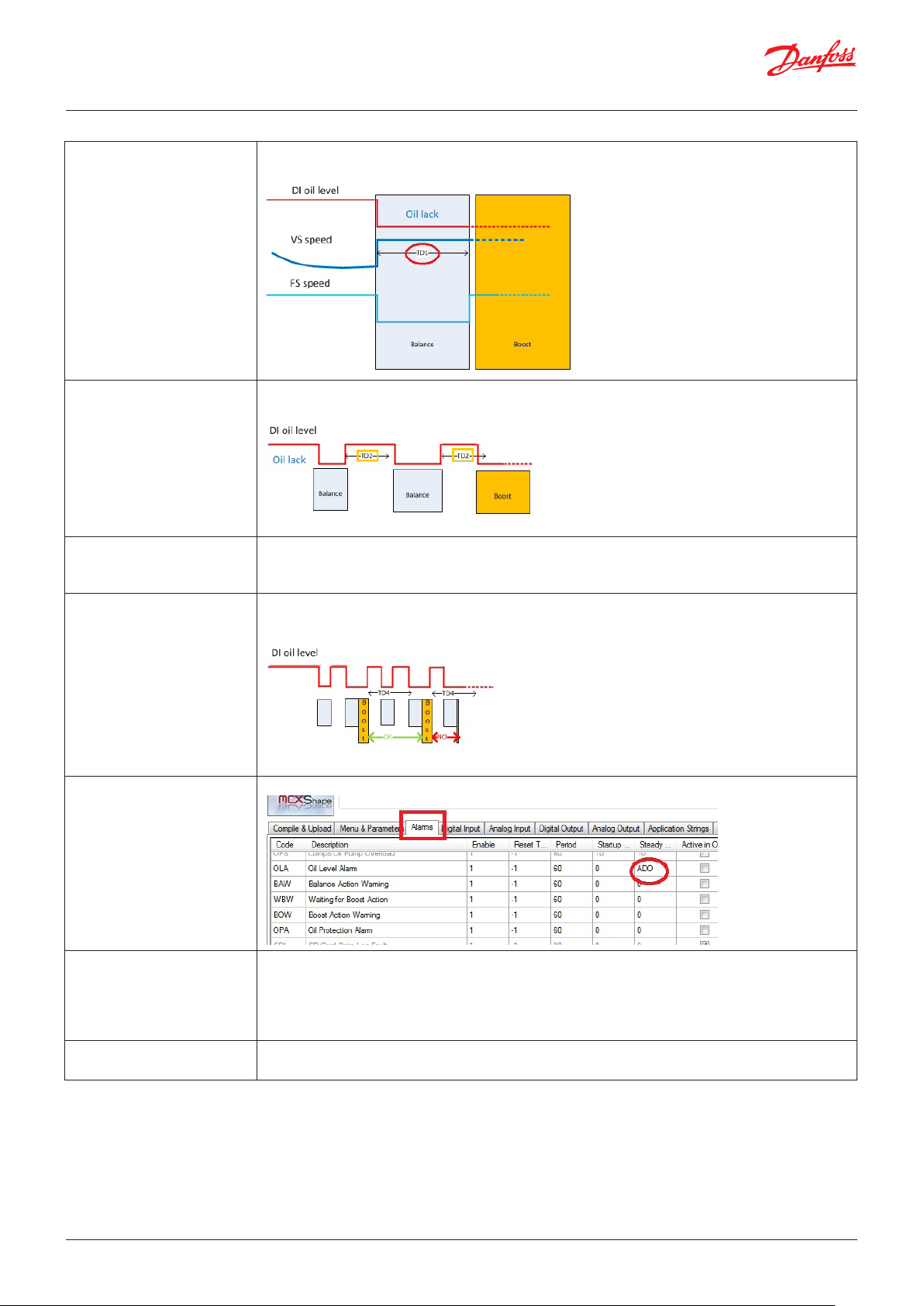
User Guide | Chiller and reversable chiller, reciprocating, scroll and screw compressors
TD1-Maximum single oil
Balance action time
TD2-Interval after stop Balance
action
TD3-Maximum single oil Boost
action time
TD4-Interval after stop Boost
action
Balance Action can take at the maximum TD1 minutes, if it will take more time, the Boost action will
be turned on
TD2 defines a minimum time in between two Balance action, if the oil lack comes sooner of TD2 the
software will perform a Boost action
Boost Action can take at the maximum TD3 minutes, if it will take more time:
- “OPA -Oil protection” alarm is generated
The Boost action is stopped
TD4 defines a minimum time in between two Boost actions, if it will take less time:
- “OPA -Oil protection” alarm is generated
- The Boost action is stopped
ADO-Start Delay Oil level
alarm
BOF-Boost action offset Defines the minimum temperature gap between the reference and water temperature which allows
BFR- Stop free cooling on
boost action
Alarm delay
to start the Boost action, if the gap is smaller than the BOF:
- “WBW - waiting for boost action” warning is generated
- The boost action is frozen (not started )
The boost action will start as soon the temperature gap will be bigger than “BOF - Boost action offset”.
Defines if free cooling is performed during the Boost action
© Danfoss | DCS (vt) | 2019.08 BC295150867120en-000201 | 71
Page 72
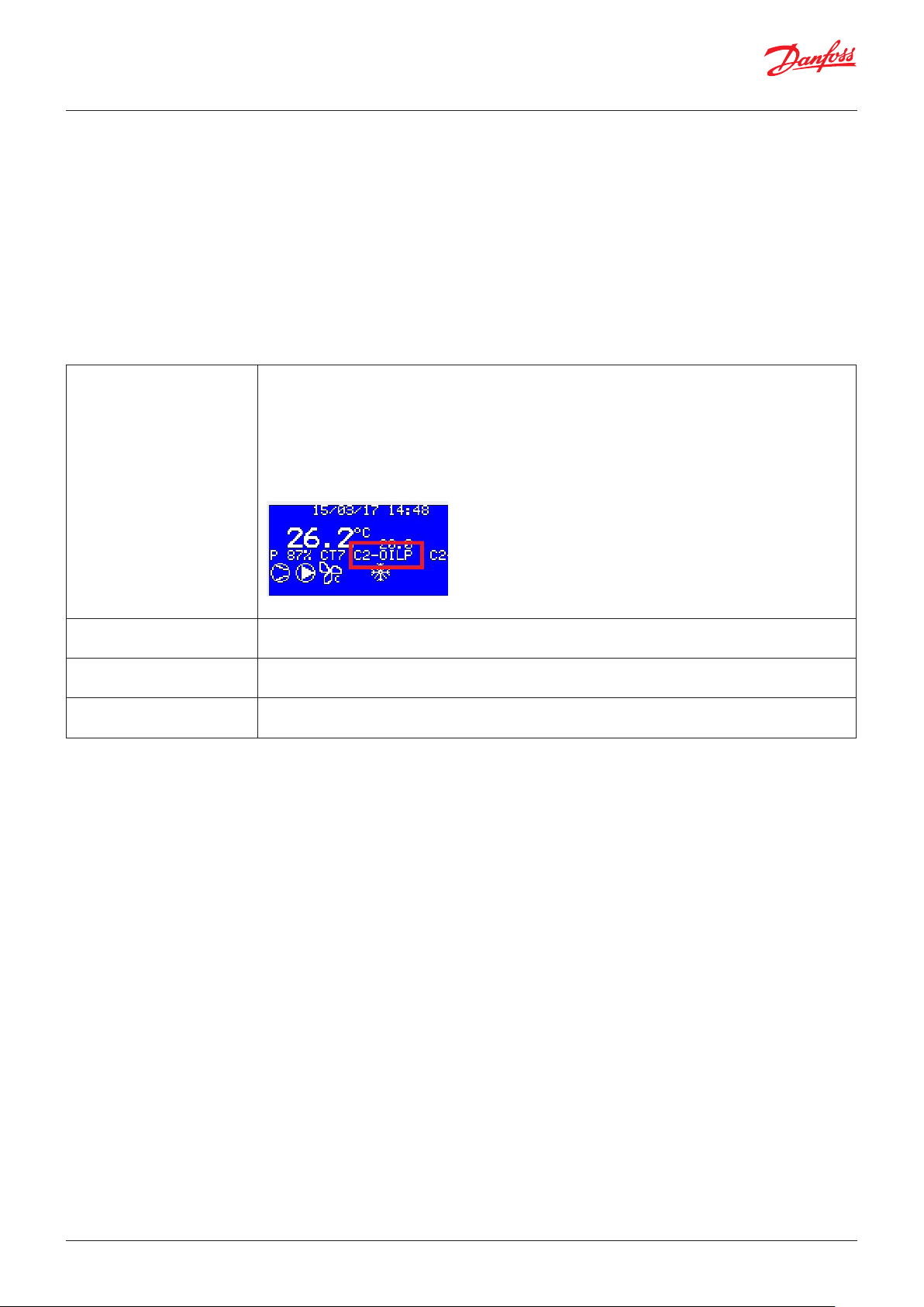
User Guide | Chiller and reversable chiller, reciprocating, scroll and screw compressors
Compressor Oil Pump
Parameter: OPE, OPO, OT1, OT2
Oil pump is used to push oil inside the compressors.
The DI_ OPx (represents the trip alarm of the oil pump) switches
off the oil pump OPx
Functionalities: Enable oil pump
Analogue input: OP1, …, OP8, Sp1, …, Sp4, dP1, …, dP4
Digital output: OP1, …, OP8
Digital input: OP1, …, OP8
Alarm: OP1, …, OP8, A8G, A8H, A8I, A8J, A8K, A8L, A8M, A8N
OPE- Oil Pump Enable 0=NO: Disable
1=ON_C: means that the oil pump OPx is switched ON OT1 seconds before the activation of
compressor x
Note: An information is shown in the “rolling text” when compressor is delayed
2=Prb means that oil pumps work as ON-C but if the delta pressure OPx – suction pressure is greater
than OdP+OPO the DO_OPx is switched off.
Oil pump starts up again when delta pressure goes below OdP+OPO
Note: CX-OILP information is shown in the “rolling text” when a compressor is delayed
OPO- Oil Pump Offset It's in bar
Check parameters OPE =Prb
OT1- Delay compressor from
oil pump
OT2- Oil pump min time ON It's in minutes
It’s in seconds
Check parameters OPE =ON_C
The oil pump has to work at least OT2 minutes before switching off
72 | BC295150867120en-000201 © Danfoss | DCS (vt) | 2019.08
Page 73

User Guide | Chiller and reversable chiller, reciprocating, scroll and screw compressors
Temperature delta of the oil
Parameter: OTD, OD1, OD2
The start of the compressor is delayed up to the temperature of
the oil is ok
Functionalities: Enable oil temperature delta control
Analogue input: OT1, …, OT8, Sp1, …, Sp4, dP1, …, dP4
Alarm: A8O, A8P, A8Q, A8R, A8S, A8T, A8U, A8V
OTD- Enable oil temperature
delta control
OD1- Oil Temperature Delta It’s in °C
OD2- Delta Control Max Time It's in minutes
0=NO: Disable
1=Yes: means that the start of the compressor is delayed up to the delta temperature OTx – T
(suction pressure ) goes above OD1 °C.
The maximum delay is OD2 seconds
Note: CX-OTD information is shown in the “rolling text” when a compressor is delayed
Check parameters OTD =Yes
Check parameters OTD =Yes
How to set the power request remotely
Parameter: RPE, RPS
- Set parameter RPE or RPS <> NO
- Write 1 to the Modbus address17501 (ADU), at least 1 time per minute
(it is used to check the connection)
- Write power request (0-1000) to the address 17502 (ADU)
- Write external coil circuit 1 speed (0-1000) to the address 17548 (ADU) -
use it also for fans in common
- Write external coil circuit 2 speed (0-1000) to the address 17549 (ADU)
- Write external coil circuit 3 speed (0-1000) to the address 17550 (ADU)
- Write external coil circuit 4 speed (0-1000) to the address 17551 (ADU)
Functionalities: Enable remote power demand
RPE - Remote power enable 0=NO means that the function is disabled
1= YESA means that without remote connection, the machine works as RPE=NO
2= YESB means that without a remote connection, the power request of the chiller goes to zero
RPS - Remote fan enable 0=NO means that the function is disabled
1=YESA means that without remote connection, the machine works as RPS=NO
2=YESB means that without remote connection, the fan speed goes to zero
© Danfoss | DCS (vt) | 2019.08 BC295150867120en-000201 | 73
Page 74
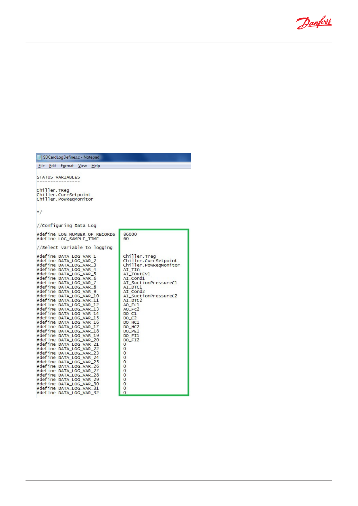
User Guide | Chiller and reversable chiller, reciprocating, scroll and screw compressors
How to log data on an SD card
Parameter: ENL
Only available for SD-card-compatible MCXs (MCX152V and MCX061V).
1- It is possible to start/stop data logging through the parameter ENL_Enable SD Card Log. If you want to restart the data logger from
zero, it is enough to delete the file from the SD card memory.
2- By editing the file SDCardLogDefines.c (in the BIN folder), it is possible to define the variables which will be stored in the SD card
3- The variables available are reported in the first part of the SDCardLogDefines.c file, consisting mainly of all the input/output functions
and a few status variables. If you are going to use variables not traced in the file, contact MCX Support
4- In the second part of the .c file, the following can be edited:
a. The number of records: when the records reach this number, the oldest record will be overwritten by the most recent (circular file)
b. Sample time: the time between two records
c. The variables to log: the maximum number of variables is 32, and the variable’s name must be the same as the first part of the .c file
5- To read the files on the SD card using a decode program, download the “DecodeLog” folder available on the MCX site and save it to the
74 | BC295150867120en-000201 © Danfoss | DCS (vt) | 2019.08
Page 75
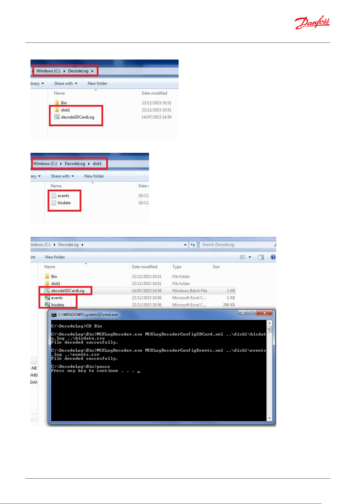
User Guide | Chiller and reversable chiller, reciprocating, scroll and screw compressors
C disk
6- Extract the memory card from the MCX and copy and paste the files to the SD card in the “DecodeLog/Disk1” folder
7- From the “DecodeLog” folder, run the batch file “decodeSDCardLog”; it will generate the .csv files with encoded data.
8- Events are recorded in the events.csv file. There are six columns:
© Danfoss | DCS (vt) | 2019.08 BC295150867120en-000201 | 75
Page 76

User Guide | Chiller and reversable chiller, reciprocating, scroll and screw compressors
a. Event time: the time of the event (start event, stop event, parameters change and RTC change)
b. EventNodeID: the ID of the MCX
c. EventType: a numerical description of the event type
i. -2: Reset of MCX history alarm
ii. -3: RTC set
iii. -4: Start alarm
iv. -5: Stop alarm
v. 1000: Parameters change (note: the change can be detected only when it is made through a user interface and not via serial
communication)
d. Var1: a numerical description of the variable. To decrypt it, open the “AGFDefine.c” file in the “App” folder of the MCXDesign software.
In this file there are two sections with an ID indication: one is for the parameters and the other is for the alarm. If the event type
is 1000, refer to the index parameters list; if the event type is -4 or -5, refer to the index alarms list. These lists contain the variable
names corresponding to each ID (not to the variable description – for the variable description, refer to MCXShape).
e. Var2: used to record the parameter value before and after the change. This number is a double integer; in the high part there is the
new parameter value and in the low part there is the old value.
f. Var3: not used.
Functionalities: Enable SD Card Log
ENL- Enable SD card log 0=NO means that the log is stopped
1=YES means that the log is started
Note: If you want to restart the data logger from zero, it is enough delating the file into the SD card memory
76 | BC295150867120en-000201 © Danfoss | DCS (vt) | 2019.08
Page 77

User Guide | Chiller and reversable chiller, reciprocating, scroll and screw compressors
Commissioning
Parameter: Ort
Overwriting an Analogue input: using the Modbus, write value 1
into the “Enable Override” register first, then it is possible to write
the “Override input value” register.
Overwriting of Digital output: write through Modbus the value 1
to the “Enable Override” register first, then it becomes possible to
write the relative bit of the “Override input value” into the register.
MCX analogue
input
1 21537 1005
2 21538 1006
….
26 21562 1030
Overwriting an Analogue output: Using Modbus, write the value
1 into the “Enable Override” register first, then it will be possible to
write the “Override input value” into the register.
MCX analogue
output
1 21505 1037
2 21506 1038
….
12 21516 1048
Overwriting of Digital input: write through Modbus the value 1
to the “Enable Override” register first, then it becomes possible to
write the relative bit of “Override input value” into the register.
MCX digital input Enable MB
1 21601 21637. Bit08
2 21602 21637. Bit09
…. … …
8 21608 21637. Bit15
9 21609 21637. Bit00
…. … …
16 21616 21637. Bit07
17 21617 21638. Bit08
24 21624 21638. Bit15
25 21625 21638. Bit00
… … …
32 21632 21628.Bit 07
Enable MB
register(ADU)
0=Disable,
1= enable
Enable MB
register(ADU)
0=Disable,
1= enable
register(ADU)
0=Disable,
1= enable
Input MB
register(ADU)
(0-1000)
Input MB
register(ADU)
(0-1000)
Input MB
register(ADU)
MCX digital output Enable MB
register(ADU)
0=Disable,
1= enable
1 21569 21635. Bit08
2 21570 21635. Bit09
…. … …
8 21576 21635. Bit15
9 21577 21635. Bit00
…. … …
16 21584 21635. Bit07
17 21585 21636. Bit08
24 21592 21636. Bit15
25 21593 21636. Bit00
… … …
32 21600 21636.Bit 07
Overwriting of functions used in the analogue input: write
through Modbus the value 1 to the “Enable Override” register
first, then it becomes possible to write the relative “Override input
value” register.
Functions for analogue inputs
Note: the order
follows the list
of functions into
MCXS
TIN-Tin evaporator 20002 18502
T01-Tout
evaporator 1
…. … …
WPR-
Water pressure
Overwriting of functions used in the digital input: use Modbus
Enable MB
register(ADU)
0=Disable,
1= enable
20003 18503
21093 18593
Input MB
register(ADU)
Input MB
register(ADU)
(0-1000)
© Danfoss | DCS (vt) | 2019.08 BC295150867120en-000201 | 77
Page 78

User Guide | Chiller and reversable chiller, reciprocating, scroll and screw compressors
to write the value 1 into the “Enable Override” register first, then it
becomes possible to write the relative “Override input value” into
the register.
Functions for digital inputs
Note: the order
follows the list
of functions
into MCXS
OC- Comp overload 21002 17502
OCL1- Comp over-
load C1
…. … …
Functionalities: Enable override of inputs and outputs
Functionalities: Enable commissioning form
Ort- Override IO Timeout It's in seconds
Enable MB
register(ADU)
0=Disable,
1= enable
21003 17503
Defines how long the override of inputs and outputs will work
Note: zero means disable
Input MB
register(ADU)
(0-1000)
Functionalities: here there is the explanation of the not reported functionalities
Enable AI probe calibration It enables the menu Cal-Probe Calibration
Enable multi input average It allows to use more than one time the same sensor, the value used into the logic is the average in
between the inputs wired with the same sensor (the broken sensor is managed)
Enable digital output
notification for alarms and
status
Enable small chiller (1C2c) It allows to save memory due to restriction on the configuration:
Enable medium chiller (2C4c) It allows to save memory due to restriction on the configuration:
Enable polarity of the AI_DI_x
functions
Enable remote keys It enables the digital inputs K01, …, K06
It enables the digital outputs NC0, N01, …, N14
Note: the purpose is the one to save memory
- 1 Circuit
- Up to 2 compressors
- 1 external coil
- 1 heater
- 2 Circuit
- Up to 4 compressors
- Up to 2 external coils
- Up to 2 internal coils
- Up to 2 heaters
It allows to set the polarity of the digital functions when they are coming from the analogue inputs
through the file BIN/AIDIPolarities.c
The DIs K01, …, K06 replicate the keys of the MCX (you’ll be able to navigate into the built in MCX
display)
78 | BC295150867120en-000201 © Danfoss | DCS (vt) | 2019.08
Page 79

User Guide | Chiller and reversable chiller, reciprocating, scroll and screw compressors
Enable remote keys for MMI The DIs K01, …, K06 replicate the keys of the MMIGRS2 (you’ll be able to navigate into the MMIGRS2
display)
Note: functionality “Enable remote keys” is required
Enable setting alarm history
events number
Enable LED display It is required for LED display (MCX06C, MMILDS)
Enable remote key
It allows to define the number of events inside the alarm history through the value beside the
functionality
Note: it effects on the amount of EEPROM available
Note: The LCD interface is always available by connecting an MMIGRS2 display over CANBUS
© Danfoss | DCS (vt) | 2019.08 BC295150867120en-000201 | 79
Page 80
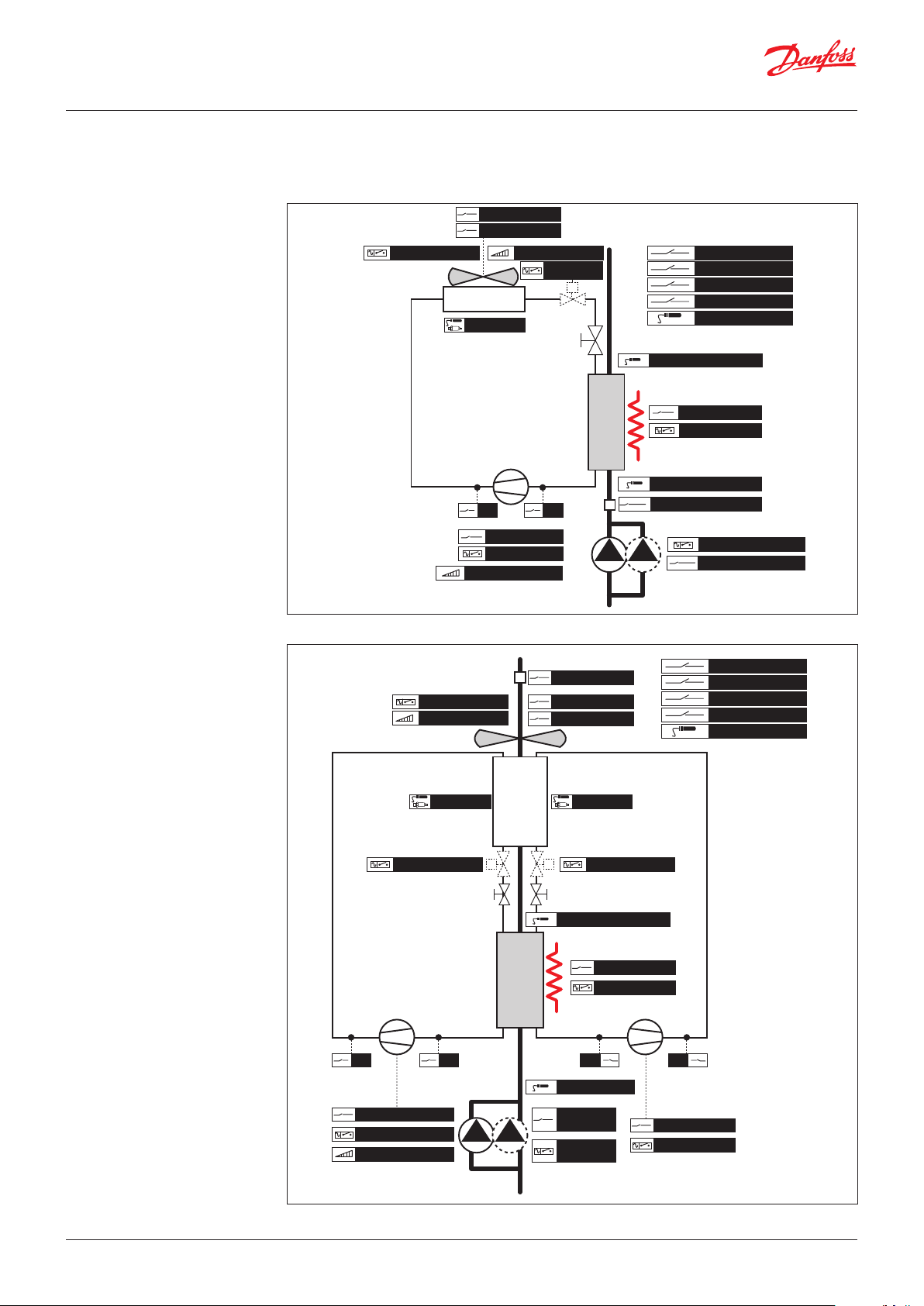
User Guide | Chiller and reversable chiller, reciprocating, scroll and screw compressors
Graphic diagrams of some of the managed unit types
Air / Water
Air / Water chiller, 1 circuit
FlowCond
CondFanOvld
CondFan ON/OFF
CONDENSER
AI_Cond
InverterComp 0 / 10 V
Inverter FanCond
compressor
Cn
HP LP
CompOvld
Comp ON/OFF
LiqValve
ON/OFF
TEV
E
V
A
P
O
R
A
T
O
R
Air / Water chiller, 1 evaporator and 1 condenser with 2 circuits
GeneralOvld
GeneralAlarm
ON/OFF
Set2
Tout
Tout Evaporator
HeaterOvld
Heater ON/OFF
Tin Evaporator
FlowEvap
EvapPump ON/OFF
EvapPumpOvld
Danfoss
80G190.01
FlowEvap
CondFan ON/OFF
Inverter FanCond
AI_Cond1 AI_Cond2
LiqValve ON/OFF LiqValve ON/OFF
circuit n. 1
compressor
Cn Cn
HP HPLP LP
Comp1Ovld
Comp ON/OFF
InverterComp 0 / 10 V
TEV TEV
C
O
N
D
E
N
S
E
R
E
V
A
P
O
R
A
T
O
R
FlowCond
CondFanOvld
Tout Evaporator
Tin Evaporator
EvapPump
ON/OFF
EvapPump
Ovld
circuit n. 2
HeaterOvld
Heater ON/OFF
compressor
GeneralOvld
GeneralAlarm
ON/OFF
Set2
Tout
Comp2Ovld
Comp2 ON / OFF
Danfoss
80G191.01
80 | BC295150867120en-000201 © Danfoss | DCS (vt) | 2019.08
Page 81
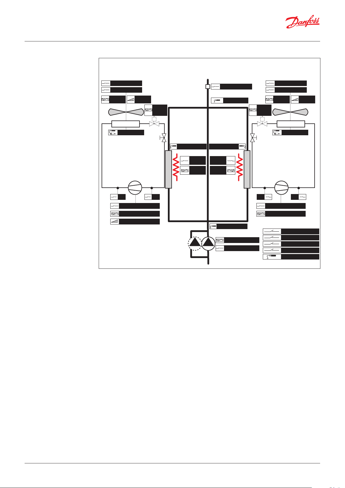
User Guide | Chiller and reversable chiller, reciprocating, scroll and screw compressors
Air / Water
Air / Water chiller, 2 circuits, 2 evaporators, 2 separated condensers
FlowCond
CondFan1Ovld CondFan2Ovld
CondFan1
ON/OFF
CONDENSER CONDENSER
FanCond1
0 / 10 V
AI_Condenser1 AI_Condenser2
circuit n. 1
compressor
Cn Cn
HP HPLP LP
Comp1Ovld Comp2Ovld
Comp1 ON/OFF Comp2 ON/OFF
InverterComp1 0 / 10 V
Liquid
valve
ON/OFF
TEV TEV
antifreeze antifreeze
Tout Evaporator1 Tout Evaporator2
E
V
A
P
O
R
A
T
O
R
Heater1
Ovld
Heater1
ON/OFF
FlowEvap
ToutEvapMix
Heater2
Ovld
Heater2
ON/OFF
TinEvaporator
PumpEvap ON/OFF
PumpEvapOvld
Liquid
valve
ON/OFF
E
V
A
P
O
R
A
T
O
R
compressor
FlowCond
CondFan2
ON/OFF
circuit n. 2
GeneralOvld
GeneralAlarm
ON/OFF
Set2
Tout
FanCond2
0 / 10 V
Danfoss
80G192.01
© Danfoss | DCS (vt) | 2019.08 BC295150867120en-000201 | 81
Page 82

User Guide | Chiller and reversable chiller, reciprocating, scroll and screw compressors
Heat Pump
Air / Water Heat Pump, 1 evaporator and 1 condenser with 2 circuits
FlowEvap
CondFan1
FanCond regulation on:
- highest value in cooling
- lowest value in heating
circuit n. 1
ON/OFF
FanCond1
0 / 10 V
O
U
T
D
O
AI_Condenser1 AI_Condenser2
Liquid valve
ON/OFF
TEV TEV
O
R
C
O
L
N
D
O
O
R
C
O
L
I
I
I
FlowCond
CondFan2Ovld
Liquid valve
ON/OFF
Tout Evaporator1
Heater1 Ovld
Heater ON/OFF
RevValveRevValve
circuit n. 2
Danfoss
80G193.01
hp
hp
chiller
compressor
HP HPLP LP
Comp1Ovld
Comp1 ON/OFF
InverterComp 0 / 10 V
chiller
Cn Cn
TinEvaporator
PumpEvap ON/OFF
PumpEvapOvld
hp
hp
chiller
compressor
Comp2Ovld
Comp2 ON/OFF
chiller
Defrost
Heat / Cool
GeneralOvld
GeneralAlarm
ON/OFF
Set2
Tout
82 | BC295150867120en-000201 © Danfoss | DCS (vt) | 2019.08
Page 83
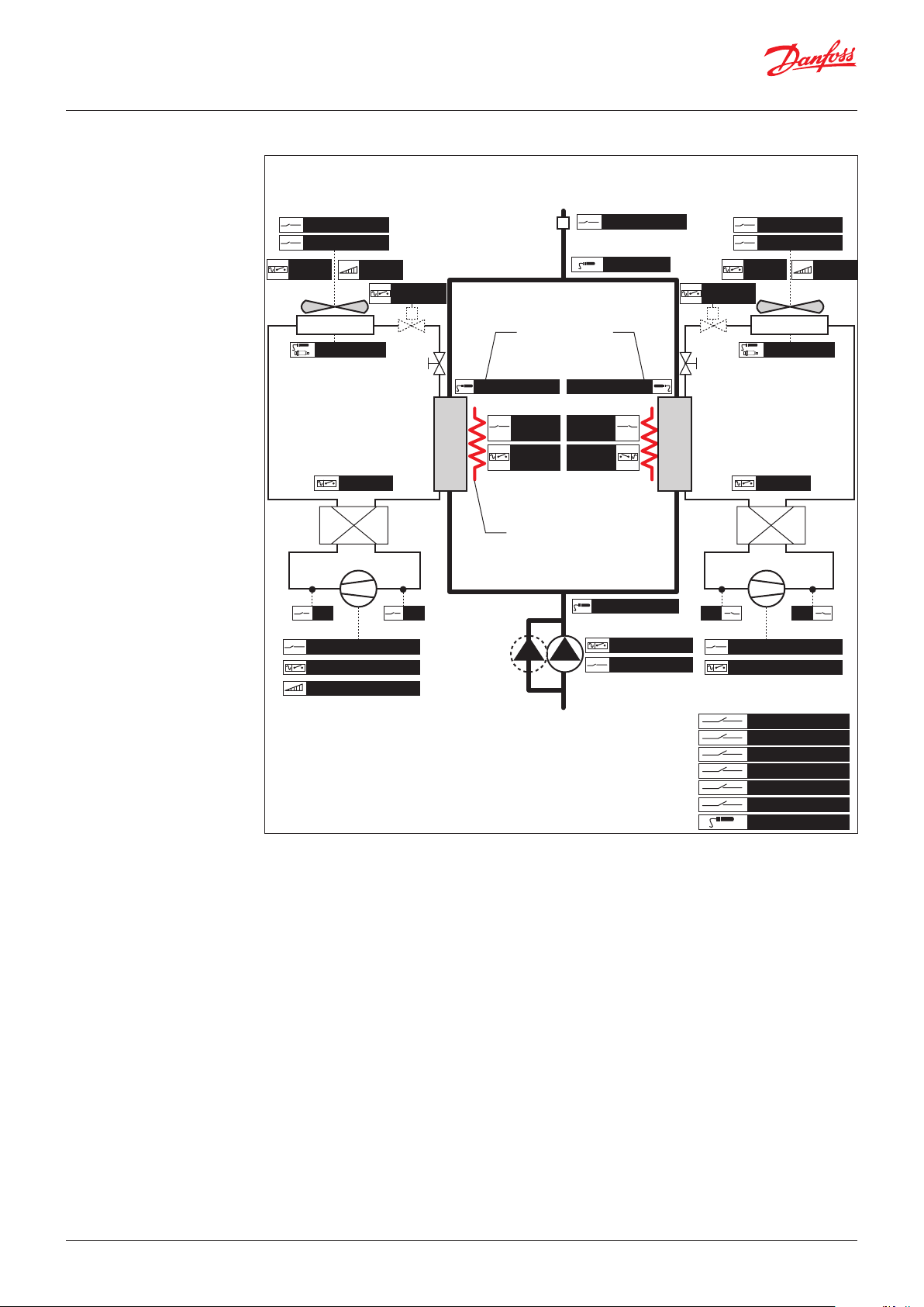
User Guide | Chiller and reversable chiller, reciprocating, scroll and screw compressors
Heat Pump
Air / Water Heat Pump, 2 circuits, 2 evaporators, 2 separated condensers
Heater1
Ovld
Heater
ON/OFF
TinEvaporator
FlowEvap
ToutEvap mix
I
N
D
O
O
R
C
O
I
L
Liquid valve
ON/OFF
TEV
FlowCond FlowCond
CondFanOvld CondFanOvld
CondFan
ON/OFF
OUTDOOR COIL OUTDOOR COIL
FanCond
0 / 10 V
Liquid valve
ON/OFF
antifreeze in cooling
AI_Condenser AI_Condenser
circuit n. 1 circuit n. 2
RevValve RevValve
hp
chiller
compressor compressor
Cn Cn
HP HPLP LP
TEV
I
N
D
O
O
R
C
O
I
L
hp
chiller
not used in heating
Tout Evaporator1 Tout Evaporator2
Heater1
Ovld
Heater
ON/OFF
antifreeze in cooling
auxiliary in heating
CondFan
ON/OFF
hp
chiller
Danfoss
80G194.01
FanCond
0 / 10 V
hp
chiller
CompOvld CompOvld
Comp ON/OFF Comp ON/OFF
InverterComp 0 / 10 V
PumpEvap ON/OFF
PumpEvapOvld
Defrost
Heat / Cool
GeneralOvld
GeneralAlarm
ON/OFF
Set2
Tout
© Danfoss | DCS (vt) | 2019.08 BC295150867120en-000201 | 83
Page 84
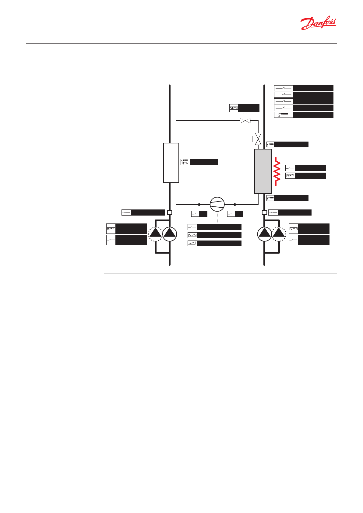
User Guide | Chiller and reversable chiller, reciprocating, scroll and screw compressors
Water / Water
Water / Water chiller, 1 circuit
FlowCond
PumpCond
ON/OFF
PumpCond
Ovld
Danfoss
80G195.01
GeneralOvld
GeneralAlarm
FlowEvap
ON/OFF
Set2
Tout
Heater1 Ovld
Heater ON/OFF
PumpEvap
ON/OFF
PumpEvap
Ovld
Liquid valve
ON/OFF
TEV
C
O
N
D
E
N
S
E
R
AI_Condenser1
compressor
Cn
HP LP
CompOvld
Comp ON/OFF
InverterComp 0 / 10 V
E
V
A
P
O
R
A
T
O
R
Tout Evaporator1
TinEvaporator1
84 | BC295150867120en-000201 © Danfoss | DCS (vt) | 2019.08
Page 85

User Guide | Chiller and reversable chiller, reciprocating, scroll and screw compressors
Water / Water
Water / Water chiller, 2 circuits, 1 evaporator, 1 condenser
C
O
N
D
AI_Condenser
FlowCond
circuit n. 1 circuit n. 2
compressor compressor
Cn Cn
HP HPLP LP
TEV
E
N
S
E
R
E
V
A
P
O
R
A
T
O
R
Liquid valve
ON/OFF
Tout Evaporator1
Heater Ovld
Heater ON/OFF
FlowEvap
GeneralOvld
GeneralAlarm
ON/OFF
Set2
Tout
Danfoss
80G196.01
CompOvld CompOvld
Comp ON/OFF Comp ON/OFF
InverterComp 0 / 10 V
PumpCond
ON/OFF
PumpCond
Ovld
PumpEvap
ON/OFF
PumpEvap
Ovld
© Danfoss | DCS (vt) | 2019.08 BC295150867120en-000201 | 85
Page 86
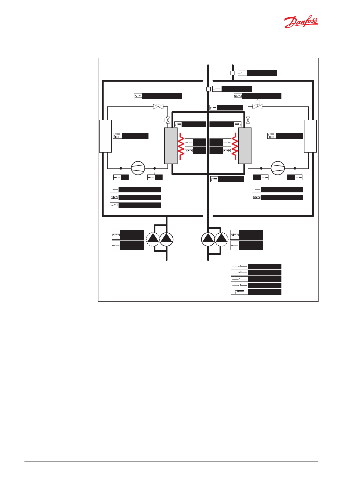
User Guide | Chiller and reversable chiller, reciprocating, scroll and screw compressors
Water / Water
Water / Water chiller, 2 circuits, 2 evaporators, 2 condensers
Liquid valve ON/OFF Liquid valve ON/OFF
Tout Evap Mix
C
O
N
D
E
N
S
E
R
AI_Condenser AI_Condenser
circuit n. 1 circuit n. 2
compressor compressor
Cn Cn
HP HPLP LP
CompOvld CompOvld
Comp ON/OFF Comp ON/OFF
InverterComp 0 / 10 V
TEV TEV
Tout Evap 1 Tout Evap 2
E
V
A
P
O
R
A
T
O
R
Heater
Ovld
Heater
ON/OFF
Heater
Ovld
Heater
ON/OFF
FlowEvap
FlowCond
E
V
A
P
O
R
A
T
O
R
Danfoss
C
O
N
D
E
N
S
E
R
80G197.01
PumpCond
ON/OFF
PumpCond
Ovld
PumpEvap
ON/OFF
PumpEvap
Ovld
GeneralOvld
GeneralAlarm
ON/OFF
Set2
Tout
86 | BC295150867120en-000201 © Danfoss | DCS (vt) | 2019.08
Page 87

User Guide | Chiller and reversable chiller, reciprocating, scroll and screw compressors
Heat Pump
Water / Water heat pump, 2 circuits, 2 evaporators, 2 condensers, gas change-over
antifreeze in heating
not used in cooling
FlowEvap
Liquid valve ON/OFF Liquid valve ON/OFF
ToutCo ToutCo
O
U
T
D
O
O
R
C
O
I
L
AI_Condenser
circuit n. 1 circuit n. 2
chiller
HP
CompOvld
Comp ON/OFF
InverterComp 0 / 10 V
RevValve RevValve
hp
compressor
TEV TEV
hp
chiller
Cn
LP
Tout Evap 1 Tout Evap 2
I
N
D
O
O
R
C
O
I
L
ToutEvap Mix
TinEvap
FlowCond
I
N
D
O
O
R
C
O
I
L
LP
AI_Condenser
hp
hp
chiller
compressor
Cn
CompOvld
Comp ON/OFF
HP
chiller
O
U
T
D
O
O
R
C
O
I
L
Danfoss
80G198.01
PumpCond
ON/OFF
PumpCond
Ovld
PumpEvap
ON/OFF
PumpEvap
Ovld
GeneralOvld
GeneralAlarm
ON/OFF
Set2
Tout
© Danfoss | DCS (vt) | 2019.08 BC295150867120en-000201 | 87
Page 88

User Guide | Chiller and reversable chiller, reciprocating, scroll and screw compressors
Heat Pump
Water / Water heat pump, 2 circuits, 2 evaporators, 2 condensers, water change-over
regulating in heating
not used in cooling
ToutCo
C
O
N
D
E
N
S
E
R
outdoor
Liquid valve ON/OFF Liquid valve ON/OFF
TEV TEV
AI_Condenser AI_Condenser
circuit n. 1 circuit n. 2
compressor
Cn
HP
CompOvld
Comp ON/OFF
InverterComp 0 / 10 V
LP
Tout Evap 1 Tout Evap 2
E
V
A
P
O
R
A
T
O
R
indoor
RevValve
FlowCond
FlowEvap
ToutEvap Mix
TinEvap
E
V
A
P
O
R
A
T
O
R
compressor
LP
CompOvld
Comp ON/OFF
Danfoss
80G199.01
C
O
N
D
E
N
S
E
R
Cn
HP
PumpCond
ON/OFF
PumpCond
Ovld
outdoor
indoor
RevValve
PumpEvap
ON/OFF
PumpEvap
Ovld
GeneralOvld
GeneralAlarm
ON/OFF
Set2
Tout
88 | BC295150867120en-000201 © Danfoss | DCS (vt) | 2019.08
Page 89
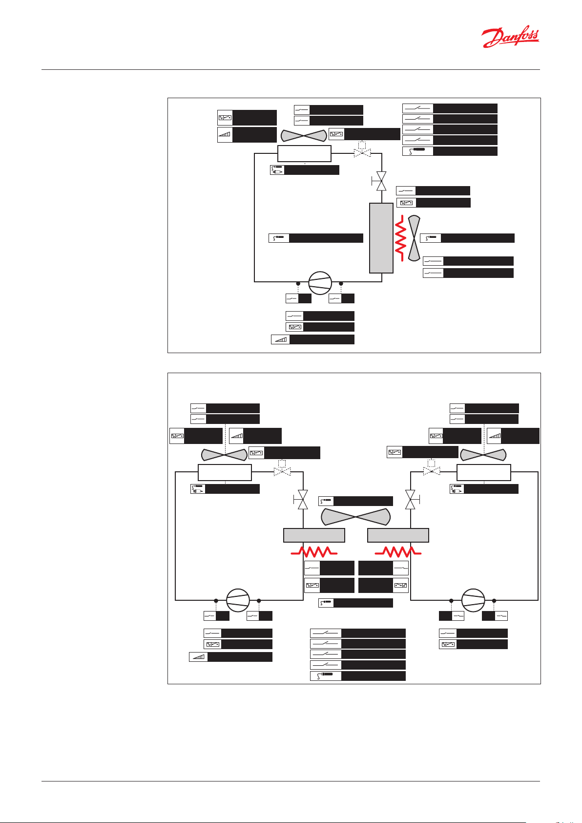
User Guide | Chiller and reversable chiller, reciprocating, scroll and screw compressors
Air / Air
Air / Air unit, 1 circuit
FanCond
ON/OFF
FanCond
0 / 10 V
FlowCond
FanCondOvld
CONDENSER
AI_Condenser
compressor
Cn
HP LP
CompOvld
Comp ON/OFF
InverterComp 0 / 10 V
Air / Air unit, 2 circuits, 2 evaporators, 2 condensers
LiqValve ON/OFF
TEV
E
V
A
P
O
R
A
T
O
R
GeneralOvld
GeneralAlarm
ON/OFF
Set2
Tout
HeaterOvld
Heater ON / OFF
Tout Evaporator 1TinEvaporator
FlowEvaporator
FanEvapOvld
Danfoss
80G1200.01
FlowCond FlowCond
FanCondOvld FanCondOvld
FanCond
ON/OFF
CONDENSER
AI_Condenser AI_Condenser
InverterComp 0 / 10 V InverterComp 0 / 10 V
FanCond
0 / 10 V
LiqValve ON/OFF LiqValve ON/OFF
TEV TEV
EVAPORATOR EVAPORATOR
compressor compressor
Cn Cn
HP HPLP LP
CompOvld CompOvld
Comp ON/OFF Comp ON/OFF
Tout Evaporator Mix
Heater
Ovld
Heater
ON / OFF
Tin Evaporator
GeneralOvld
GeneralAlarm
ON/OFF
Set2
Tout
Heater
Ovld
Heater
ON / OFF
FanCond
ON/OFF
CONDENSER
FanCond
0 / 10 V
Danfoss
80G1201.01
© Danfoss | DCS (vt) | 2019.08 BC295150867120en-000201 | 89
Page 90
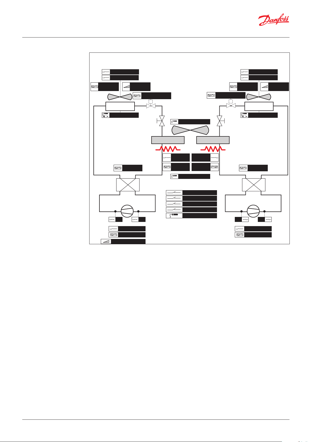
User Guide | Chiller and reversable chiller, reciprocating, scroll and screw compressors
Heat Pump
Air / Air heat pump, 2 circuits, 2 evaporators, 2 condensers
FlowCond FlowCond
FanCondOvld FanCondOvld
FanCond
ON/OFF
CONDENSER
AI_Condenser AI_Condenser
FanCond
0 / 10 V
LiqValve ON/OFF
TEV TEV
EVAPORATOR EVAPORATOR
RevValve RevValve
hp
hp
chiller
compressor compressor
HP HPLP LP
chiller
Cn Cn
Tout Evaporator Mix
Heater
Ovld
Heater
ON / OFF
Tin Evaporator
GeneralOvld
GeneralAlarm
ON/OFF
Set2
Tout
Heater
Ovld
Heater
ON / OFF
LiqValve ON/OFF
FanCond
ON/OFF
hp
chiller
CONDENSER
hp
chiller
FanCond
0 / 10 V
Danfoss
80G1202.01
CompOvld CompOvld
Comp ON/OFF Comp ON/OFF
InverterComp 0 / 10 V InverterComp 0 / 10 V
90 | BC295150867120en-000201 © Danfoss | DCS (vt) | 2019.08
Page 91

User Guide | Chiller and reversable chiller, reciprocating, scroll and screw compressors
Status variables
The following variable are available through Modbus, they are the
states of the software.
The variables which can work as command are set as R/W variable
Software status
Parameter: A01, …, A19, C01, …, C04, E01, …, E08
A01- Main command
(R/W)
A02-Alarm notification
(R)
A03-Pump
(R)
A04-Fun
(R)
A05-Heaters
(R)
A06-Remote ON-OFF (R) 0= OFF: the digital input ONO_ON/OFF is in OFF
A07-Defrost status (R) 0= OFF
A08-Request power
(R)
A09-Actual power
(R)
A10-Hours Counter Saving
(R/W)
A11-Actual control probe (R) This is the probe used for the regulation of the compressors
A12-Actual setpoint (R) This is the real setpoint used for the regulation of the compressors
A13-Status System(R) 0= Off chiller
A14-Cooling-Heating(R) 0= Cool
C01-C04
Compressor x Pow(R)
E01-E08
Compressor x (R)
0: no meaning, the software reads and sets to zero this variable each loop
1: writing 1, the buzzer stops
2: writing 2, the alarms are reset
3: writing 3, the default parameters are restored
4: writing 4, the parameter y01-System On Off is changed
7: writing 7, the alarm history are reset
8: writing 8, heat/cool mode is changed
0: means that there are not alarms
1: means that there are alarm or warning active
2: means that buzzer is working
0= Off
1= ON
0= Off
1= ON: at least one fan is switched on
0= Off
1= ON: at least one heater is switched on
1= ON: the digital input ONO_ON/OFF is in ON
1= ON: the defrost is performed
It's in %
It’s the power request for the compressors
It's in %
It’s the power available in the moment; it depends on alarms, temporization, etc.
Writing 1 all the counters are stored in persistent memory
Note: the hour counters are usually stored every 20 minutes
Note: the setpoint also considers compensations
1= On chiller
1= Heat
It's in %
The screw compressor power is
0= Compressor is switched OFF
1= Compressor is waiting to switch ON
3= Compressor is waiting to switch OFF
4= Compressor is switched ON
© Danfoss | DCS (vt) | 2019.08 BC295150867120en-000201 | 91
Page 92

User Guide | Chiller and reversable chiller, reciprocating, scroll and screw compressors
Software info
Parameter: F01, …, F07
The information about the software is available in the
Service/ Software info menus or through Modbus.
F01-Application ID (R) This is the software identification
F02-Major (R) Defines a major change in the software
F03-Minor (R) Defines a change in the .mcxs file (new parameters etc.)
F04-Patch (R) Defines a minor change into the logic
F05-Build (R) Changed whenever compiling takes place
F06-Control File Version (R) This is equal to the parameter Par-Parameters version
F07-Build option (R) This depends on the compilation of the software; different configurations (functionalities, inputs and
outputs) will change a value
92 | BC295150867120en-000201 © Danfoss | DCS (vt) | 2019.08
Page 93

User Guide | Chiller and reversable chiller, reciprocating, scroll and screw compressors
Superheat info
Parameter: H01, …, H13
H01-Valve position v1 (R) It’s in %
H02-S2 Temperature v1 (R) It's in °C
It’s the evaporator outlet temperature
H03-Superheat v1 (R) It's in °C
H04-Superheat reference v1 (R) It's in °C
H05-Pe pressure v1 (R) It's in bar
This is the evaporator pressure
H06-Te temperature v1 (R) It's in °C
This is the evaporator’s temperature calculated from the evaporator’s pressure
H07-S4 temperature v1 (R) It's in °C
This is a sensor for measuring air temperature
H08-Main switch v1 (R) 0= Stop
1= Start
© Danfoss | DCS (vt) | 2019.08 BC295150867120en-000201 | 93
Page 94

© Danfoss | DCS (vt) | 2019.08 BC295150867120en-000201 | 94
ADAP-KOOL®
 Loading...