

Page 1
Installation guide
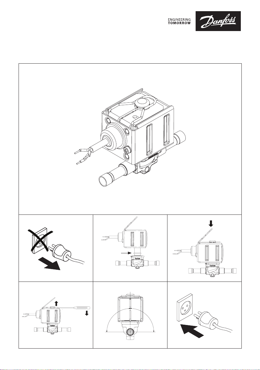
Solenoid coil for control in potentially explosive areas
Type BZ
018R9667
1 2 3
Danfoss
32U10102.10
O-ring*
Danfoss
32U10101.10
Danfoss
018R9667
32U10103.10
*Recommended to reduce vibrations.
Not required for sealing.
4 5 6
Danfoss
32U10100.10
9
0
Danfoss
32U10104.10
© Danfoss | Climate solutions | 2021.11
X
A
° M
90
°
MA
X
AN199286440918en-000601 | 1
Page 2
32U10106.10
A
7
Spare part no. 018F4703
6
Tambient -40T45 ºC
110V 50HZ 0,14A
120V 60HZ 0,13A
5
Danfoss A/S, 6430 Nordborg, Denmark
22 Wycombe End, HP9 1NB, GB
Date of manufacturing
2
xxxx
B
MADE IN CHINA
Type BZ120C
Year
Week
F4753
II 2G
0539
9
4
2
Ex mb IIC T4 Gb
DEMKO 14 ATEX 1314X
IECEx ULD.14.0001X
UL21UKEX2020X
0843
11
8
1
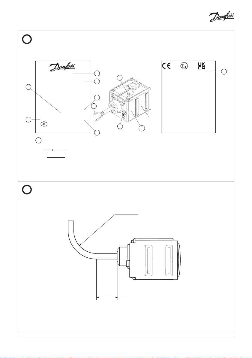
Warnings
Marking
3
10
Do not seperate coil from
the valve when energized.
See instruction
r > 55mm
© Danfoss | Climate solutions | 2021.11
Danfoss
The installer must fix the cable in a
position close to the coil to ensure
that the first 20 mm cannot be bent.
AN199286440918en-000601 | 2
Page 3

A
Identification
1
Green/Yellow cord for earthing
2
Week and year of manufacturing
3
External earth terminal
4
Code number
5
Voltage
6
Frequency
7
Current
8
Ambient temperature range
9
Country of manufacturing
10
Enclosure
11
Approval/Certificate number
Description and approval
Solenoid valve for control in potentially
explosive area.
EU Directives
EMC 2014/30/EU
ROHs 2011/6 5/EU
ATEX 2014/34/EU
Certifications
Ex mb IIC T4 Gb
DEMKO 14 ATEX 1314X
IECEx ULD 14.0001X
UL21UKEX2020X
The coil may only be installed with following valve combinations
• EVR NC 2 - 25
• EVRA(T) 3 - 25
• EVRS(T) 3 - 20
• EVRB
• EVRF
• EVM NC and EVM NO
• EV220B 6 - 22 NC
• EV220B 6 - 10 NO
• EV220B 15 - 50 NC
• EV250B
• EV251B
• EV222B
• EV224B
• EV227B
Application and specification
Nominal
voltage
Frequency Nominal
current
Size of
fuse in
front of
the coil
Ambient
temperature
Media
temperature
Permissible
voltage
variation
[V] [Hz] [A] [mA] [°C] [°C] [%]
24 DC 0.43 500 -40 – 45 -40 – 70 -10 +5 018F4705
110
120
230
240
50
60
50
60
0.14
0.13
0.09
0.08
250 -40 – 45 -40 – 70 -10 +6 018F4703
150 -40 – 45 -40 – 70 -10 +6 018F470 4
Code no.
Ambient temperature -40 – 45 °C Polution degree 1+2+3 (EN60730-1)
Media temperature -40 – 70 °C Over voltage category III (EN60730-1)
Humidity 0% < RH < 100% Mode of operation Type 1 action (EN60730-1)
Connection
3-core flexible cable 3 x 0.75 mm²
Type of control Incorporated control
(EN60730 -1)
External earth core Minimum area > 4 mm² Protection against
electrical shock Class I (EN60730-1)
Weight exclude valve 0.4 kg exclude cable Protection degree IP65 (IEC 60529)
© Danfoss | Climate solutions | 2021.11
AN199286440918en-000601 | 3
Page 4

Safety instruction
All national safety regulations must be
complied with in connection with
installation, start-up and operation of
Danfoss solenoid valve. Furthermore, the
requirements of the declaration of
conformity and national regulations for
installation in explosion area. Disregarding
such regulations involves a risk of serious
personal injury or extensive material
damage. Work in connection with the
solenoid valve mentioned must be
performed only by suitable qualified persons.
Safety requirements for use in explosive
atmospheres are fullfilled through
compliance certificates:
• EX mb IIC T4 Gb
• DEMKO 14 ATEX 1314X
• IECx ULD 14.0001X
• UL21UKEX2020X
Installation, operation and maintenance
• Protect the coil against external impact
• Protect the coil against direct sunlight and
other ultraviolet sources
• Disconnect the power before dismounting
the coil
• An external fuse (standard DIN41571-2) is
required to protect coils as follows:
018F4703: 250 mA, 1500 A Breaking capacity,
250 V, Medium Time lag
018F4704: 150 mA, 1500 A Breaking capacity,
250 V, Medium Time lag
018F4705: 500 mA, 1500 A Breaking capacity,
250 V, Medium Time lag
The Power supplying the solenoid must be
limited to a prospective short circuit current
of a maximum 1500 A
• Install the coil and cable according to
IEC/EN/ EN BS 60079-14
• The cable supplied with the solenoids
must not be handled or flexed, and shall
be protected against impact if the ambient
temperature is below 0 °C
• Installation and handling of the cable shall
be done at temperature above 0 °C
• The cable is only for fixed installation and
the minimum bending diameter for fixed
installation: r ≥ 55 mm ( 2 )
B
• The cable jacket material is PVC
• The cable operating temperature range is
-40 – 90 °C
• The product is provided with a yellow/green
PE wire as well as an external earth terminal.
These shall not be used simultaneously.
If the external earth connection is connected
to earth or bonding system, the Y/G earth
wire must be cut off, isolated and not con nected. If the Y/G wire is connected to earth,
the external earth terminal must be left
without any connection. For the external
earth terminal the size of the earth core shall
be minimum 4 mm² and the installer shall
use a suitable method e.g. crimp terminal
to ensure secureness of the external earth
connection. The screw for external PE shall
be mounted with 1.2 Nm ± 0.2.The external
earth conductors shall be physically secured
close to the coil connection to ensure that
the conductors cannot be readily loosened
or twisted
• The end user must ensure the earthing of
the coil is maintained
• Non-detachable cords method Z repairing not
allowed. If the coil failed, it must be replaced
by a new coil
UK-CA contact address:
Danfoss Ltd.
22 Wycombe End,
HP9 1NB, GB
CE contact address:
Danfoss A/S
DK-6430 Nordborg
Denmark
© Danfoss | Climate solutions | 2021.11
AN199286440918en-000601 | 4
 Loading...