

Page 1
Installation Guide
BV 1 and BV 2
Block valves
HCFC, HFC, R717 (Ammonia), R744 (CO2)
006R9501
006R9501
BV 1 BV 2 Coil
BV 1 & BV 2
Connections DN 10/DN15
Max. working pressure, PB = 28 bar (Pe)
Test pressure p' = 42 bar (Pe)
Medium temperature = −40°C → 105°C
EVRST:
Min. opening di. pressure = 0
Max. opening di. pressure
with 12 W coil: 21 bar
with 10 W coil: 14 bar
© Danfoss A/S (AC-MCI/MWA), 2012-11 DKRCI.PI.FP0.A1.02 / 520H7038 1
Page 2
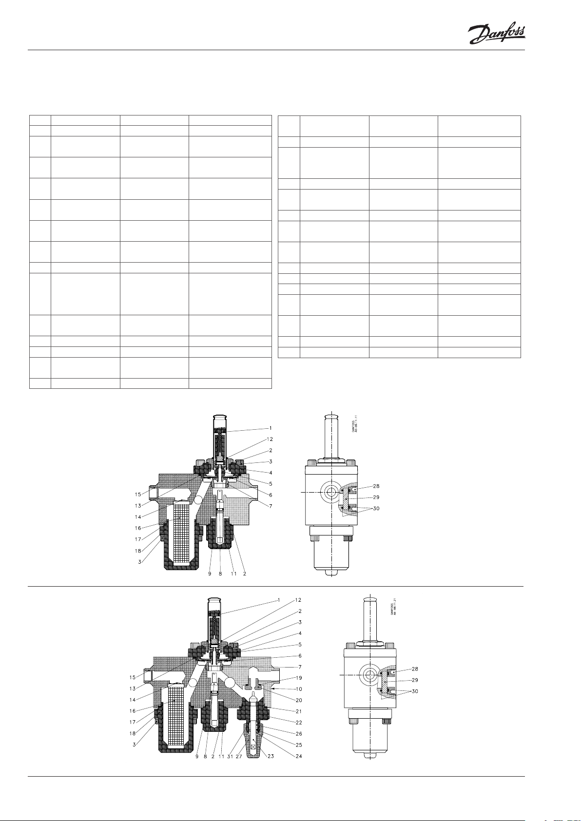
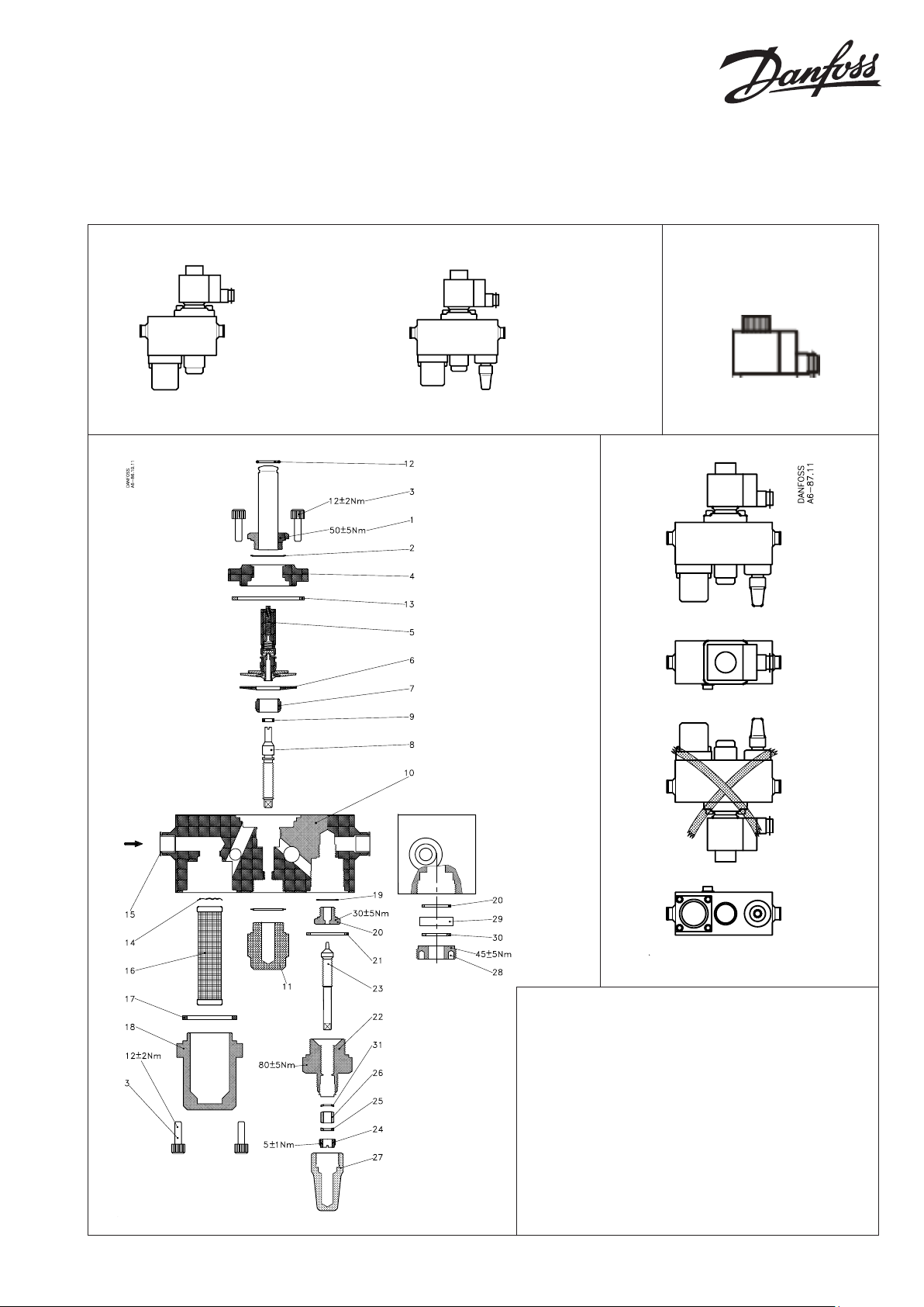
Part list is referring to drawings both at the previous and this page
No. Part Material DIN
1 Ass. Armature Stainless steel X 2 Cr N i 19 -11
2 Gasket Aluminium
3 Screw M6x20 Stainless steel RS A2-70 912
W 1- 4301
4 Cover Stainless steel EN 10204
W 1-430 8
5 Ass. Diagphram/
armature
6 Washer Stainless steel X5C rNi18-10
7 Valve seat Stainless steel 18/8 Free cutting st.
8 Spindle manual Stainless steel 18/8 Free cutting st.
9 O-ring Chloropren Chloropren
10 Valve Block Stainless steel SANMAC
11 Cap Stainless steel 18/8 Free cutting st.
12 O-ring Chloropren Chloropren
13 Rubber gasket Chloropren Chloropren
14 Crinkled spring
washer
15 Cap Plastics Plastics
Stainless steel/
teflon tissure
W 1- 4301
W 1-4305
W 1-4305
304/304L
EN10088 -3
W 1-4307
W 1-4305
Spring steel Spring steel
No. Part Material DIN
16 Strainer insert
FA 15
17 Refrig. Gasket Klingersil C4430 C4430
18 Strainer housing Stainless steel 18/8 Free cutting st.
19 Gasket Aluminium 30,255
20 Orifice Stainless steel X10CrNiS 18-9
21 Refrig. Gasket Klingersil C4430 C4430
22 Shaft sealing Stainless steel EN 10088
23 Spindle Stainless steel X10CiN iS 18 -9
24 Sealing nut Stainless steel W 1- 4305
25 Sealing nut Stainless steel
26 Teflon gasket Tefl on Tefl on
27 Cap 6F Stainless steel 18/8 Free cutting st.
28 Sealing ring Stainless steel 18/8 Free cutting st.
29 Glass Glass Glass
30 O-ring Chloropren Chloropren
Stainless steel
tissue
Stainless steel tissue
W 1-4305
EN 10088
W 1-4305
W 1-4305
W 1-4305
W 1-4305
W 1-4305
BV 1
BV 2
2 DKRCI.PI.FP0.A1.02 / 520H7038 © Danfoss A/S (AC-MCI/MWA), 2012-11
Page 3

Refrigerants:
Applicable to HCFC, HFC, R717 (Ammonia) and R744 (CO2).
Installation:
The valve must be installed in ow direction (arrow).
It is recommended to disassemble the valve before welding and/
or to use a wet cloth wrapped around the valve body to prevent
heat generation from welding to damage the internal parts of the
valve.
Capacity
Service:
At servicing and maintenance of the complete valve, it is recommended to change the orice, manual spindle, diaphragm
and armature in the solenoid valve part as well as the orice and
spindle assembly in the regulating unit.
Spare part set containing these components can be found in the
spare parts manual.
Typ e kv value
m3/h
Connections
BV 1 1,52*) DN 10
DN15
BV 2 0,36*)
0,77*)
*) Fully open valves
DN 10
DN 15
Capacity
kv-curves for BV 2
Number of spindle
rotations from
closed valve
The curves are based on subcooled liquid ahead of valve (no ashgas)
© Danfoss A/S (AC-MCI/MWA), 2012-11 DKRCI.PI.FP0.A1.02 / 520H7038 3
Page 4

www.danfoss.com/ir
4 DKRCI.PI.FP0.A1.02 / 520H7038 © Danfoss A/S (AC-MCI/MWA), 2012-11
 Loading...