

Page 1

Installation guide
1
5
°
M
A
X
1
5
M
A
X
1
5
°
A
X
1
5
M
A
X
!
Solenoid coil for control in potentially explosive areas
Type BI
A B
018R9600
018R9600Info for UK customers only: 22 Wycombe End, HP9 1NB, GB
1
4
90°
© Danfoss | Climate Solutions | 2022.03
EV
AKV
2
°
5
3
°
M
6
AN381048038901en-000101 | 1
Page 2
7
Nordborg
,
ycomb
,
,
643
0
N
g
,
22W
y
e
End
,
9
1
,
GB
EIN
C
A
CO
8 9
1.5 Nm ± 0.15 Nm
10 11
II
1
2
3
0539
Exmb IICT4 Gb
IECExULD 21.0024X
UL21ATEX 2606X
UL21UKEX2374X
-40°C≤Ta ≤40°C
240V50/60Hz0,047A
0843
II2G
Z8525
I
r > 35mm
9
comb
MAD
0539
Exmb IICT4Gb
IECExULD 21.0024X
UL21 ATEX 2606X
UL21UKEX2374X
-40°C≤Ta≤40°C
240V50/60Hz0,047A
5
ordbor
IL018Z8585
II2G
4
DK
HP
NB
HIN
0843
Z8525
7
8
610
© Danfoss | Climate Solutions | 2022.03
AN381048038901en-000101 | 2
Page 3

II
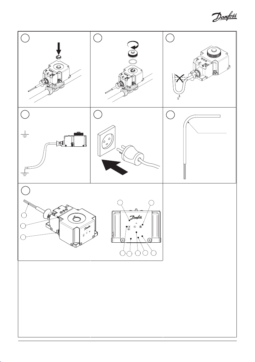
Identification
1
Green/Yellow cord for earthing
2
Week and date of manufacturing
3
External earth terminal
4
Code number
5
Voltage
6
Approval/Certificate number
7
Frequency
8
Ambient temperature range
9
Country of manufacturing
10
Approval logos
Description and approval
Solenoid valve for control in potentially
explosive area.
EU Directives
ATEX 2014/34/EU
EMC 2014/30/EU
RoHS Directive 2011/65/EU
- including amendment 2015/863
EX Certifications
Ex mb IIC T4 Gb
IECEx ULD 21.0024X
UL 21 ATEX 2606X
UL21UKEX2374X
The coil may only be installed with following valve combinations
Valves works with A: Valves works with B: Valves works with both:
• EVM-EVRF-EVRP-EVRB
• AKV
• EVR 2, 3, 6
• EVRS(T) 3
• EV210BW
• EV210B
• ICLX
• VDH
• VDHT EAM
• VDHT
• VPH
• EVRA 3
• E V220B 6, 10, 12, 14, 18, 22
• EV221BW
• EV251B
• EVRS(T) 10-20
• ICF
• EV227B
• EVRA 10, 15, 20 (Before 1996)
• EVRA(T) 10, 15, 20 (Before 1996)
• E VR 10, 15, 20, 22, 25, 32, 40
• E V220B 15, 20, 25, 32, 40, 50
• EV220BW
• EV220B 65, 80, 100
• EV250BW
• EV250B
• VDH 30 EC
• EV222B
• EV224B
• EVRA 10, 15, 20, 25, 32, 40
(After 1996)
• EVRA(T) 10, 15, 20 (After 1996)
• AK VA
• EVRA(T) 3
Application and specification:
Ambient temp. -40 °C ≤ T
Media -40 °C < T
≤ +40 °C Protection degree IP67(Evaluated by Danfoss)
ambient
< +90 °C Polution degree 3 (EN60730-1)
media
Humidity 0 - 97 % Over voltage category II (2.5 kV)
Voltage +6 / -10 % Mode of operation Type 1 action (EN60730-1)
Connection 3-Wire cable 3 x 0.75mm² External earth wire Minimum wire gauge
> 4mm²
Weight 1.0 kg Purpose of control Independently mounted/
incorporated class I control
© Danfoss | Climate Solutions | 2022.03
AN381048038901en-000101 | 3
Page 4

Safety instruction
All national safety regulations must be
complied with in connection with
installation, start-up and operation of
Danfoss solenoid valve. Furthermore, the
requirements of the declaration of
conformity and national regulations for
installation in explosion area. Disregarding
such regulations involves a risk of serious
personal injury or extensive material
damage. Work in connection with the
solenoid valve mentioned must be
performed only by suitable qualified persons.
Safety requirements for use in explosive
atmospheres are fullfilled through
compliance certificates:
• Ex mb IIC T4 Gb
• IECEx ULD 21.0024X
• UL 21 ATEX 2606X
• UL21UKEX2374X
Specific Condition of Safe Use
• Protect the coil against external impact
• Protect the coil against direct sunlight and
other ultraviolet sources
• Disconnect the power before dismounting
the coil
• Install the coil and cable according to
IEC/EN/ EN BS 60079-14
• The cable supplied with the solenoids
must not be handled or flexed, and shall
be protected against impact if the ambient
temperature is below 0 °C
• Installation and handling of the cable shall
be done at temperature above 0 °C
• The cable is only for fixed installation and
the minimum bending diameter for fixed
installation: r ≥ 35 mm ( 2 )
I
• The cable jacket material is PVC
• The cable operating temperature range is
-40 – 90 °C
• The product is provided with a yellow/green
PE Conductor as well as an external earth
terminal. These shall not be used simultaneously.
If the external earth connection is connected
to earth or bonding system, the PE Conductor must be cut off, isolated and not con nected. If the PE Conductor is connected to
earth, the external earth terminal must be
left without any connection. For the external
earth terminal the size of the earth core shall
be minimum 4 mm² and the installer shall
use a suitable method e.g. crimp terminal
to ensure secureness of the external earth
connection. The screw for external PE shall
be mounted with 1.2 Nm ± 0.2. The external
earth conductors shall be physically secured
close to the coil connection to ensure that
the conductors cannot be readily loosened
or twisted
• The end user must ensure the earthing of
the coil is maintained
• Non-detachable cords method Z repairing not
allowed. If the coil failed, it must be replaced
by a new coil
UK-CA contact address:
Danfoss Ltd.
22 Wycombe End,
HP9 1NB, GB
CE contact address:
Danfoss A/S
DK-6430 Nordborg
Denmark
© Danfoss | Climate Solutions | 2022.03
AN381048038901en-000101 | 4
 Loading...