

Page 1
Dan
70-1122.11
.13
Data sheet
Oil Motor Pump type BFPM 21
Application
Function
The BFPM range is a series of Danfoss oil pumps in
combination with a highly efficient permanent
magnet motor.
The BFPM Electronic Controller must be used for
controlling BFPM motor pumps (see separate data
sheet for BFPM Electronic Controller).
BFPM 21 is designed for small domestic oil
burners up to 24 l/h.
BFPM 21 features:
• Light oil and kerosene
• 1- or 2-pipe operation
• 1-stage
• Built-in pressure regulator
• Solenoid valve cut-off
• Cartridge filter
O
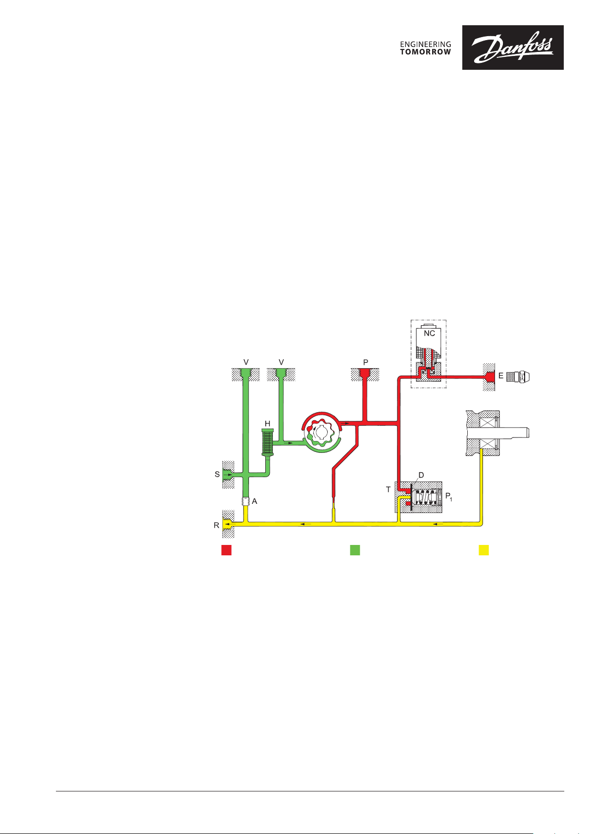
Pressure Suction Return
From the suction inlet (S) oil is drawn through the
filter (H) to the gear set, where the pressure is
increased. When voltage is applied to the
NC-valve, it opens and releases oil to the nozzle
outlet.
By means of the diaphragm (D) in the pressure
regulator (T), the pressure is kept constant at the
value set on adjustment screw (P1).
In 2-pipe systems the excess oil is led back to the
return outlet (R) and the tank.
In 1-pipe systems with plugged return outlet (R)
and screw (A) removed, the oil is returned
internally to the gear set (see figure).
Cut-off function, solenoid valve
When the burner stops, the voltage to the
NC-valve is cut off and the oil flow to the nozzle
outlet is cut off immediately.
foss
Bleeding
In 2-pipe systems the pump is self-priming, i.e.
bleeding is performed via the constriction (O) to
the return outlet (R).
In 1-pipe systems with plugged return outlet (R),
bleeding must be performed through the nozzle
outlet (E) or the pressure gauge port (P).
Warranty
For pumps used outside the stated technical data
and used with oil containing abrasive particles
Danfoss cannot give any warranty.
Note! The solenoid valve must be replaced after
250.000 operations or 10 years (approved life
expectancy).
© Danfoss | 2019.05
VD.DK.L3.02| 1
Page 2
Data sheet Oil Motor Pump type BFPM 21
Identification
Technical Data
BFPM 2 1 L 3 L
L: left hand nozzle outlet
3: capacity 24 l/h
L: left hand rotation
1: with one solenoid valve
2: cartridge filter, pressure adjustment on front
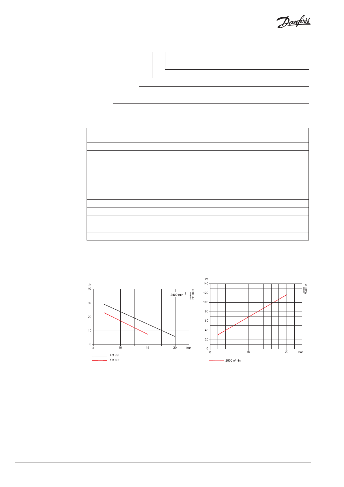
Nozzle capacity at 4.3 cSt., 10 bar, 2800 min
Oil types
-1
Standard fuel gas oil and fuel gas oil acc. to DIN V
51603-6 EL A Bio-10 (Max. 10% FAME)
Viscosity range (measured in suction inlet) (1.3) 1.8 to 12.0 cSt. (mm2/s)
Filter area/mesh 11 cm²/200 µm
Pressure range
1)
7 to 20 bar
Default setting 10 ±1 bar
Max. pressure in suction inlet/return outlet 2 bar
Speed 400 to 3400 min
-1
Ambient/transport temperature -20 to +70° C
Temperature of medium 0 to +70° C
Power supply/drive BFPM motor
2)
230 V switched from controller
Coil power consumption 9 W
Coil rated voltage (other voltages on request) 220/240V, 50/60 Hz
Coil enclosure IP 40
1)
Max. 12 bar at 1.3 cSt., max. 15 bar at 1.8 cSt.
2)
Warning: Do not connect BFPM motor directly to 230 V/50 Hz power supply!
Nozzle capacity Power consumption
2 | © Danfoss | 2019.05
VD.DK.L3.02
Page 3

Data sheet Oil Motor Pump type BFPM 21
Connections
Change-over and
Filter Replacement
P1: Pressure adjustment
S: Suction inlet G1/4
R: Return outlet G1/4
E: Nozzle outlet G1/8
P: Pressure gauge port G1/8
V: Vacuum gauge port G1/8
H: Filter
H: Filter
A: 2-pipe operation, with screw
B: 1-pipe operation, without screw
Dimensions
VD.DK.L3.02
© Danfoss | 2019.05 | 3
Page 4
Danfos
produc
Al
Danfoss A/S
Heating Segment • heating
Data sheet Oil Motor Pump type BFPM 21
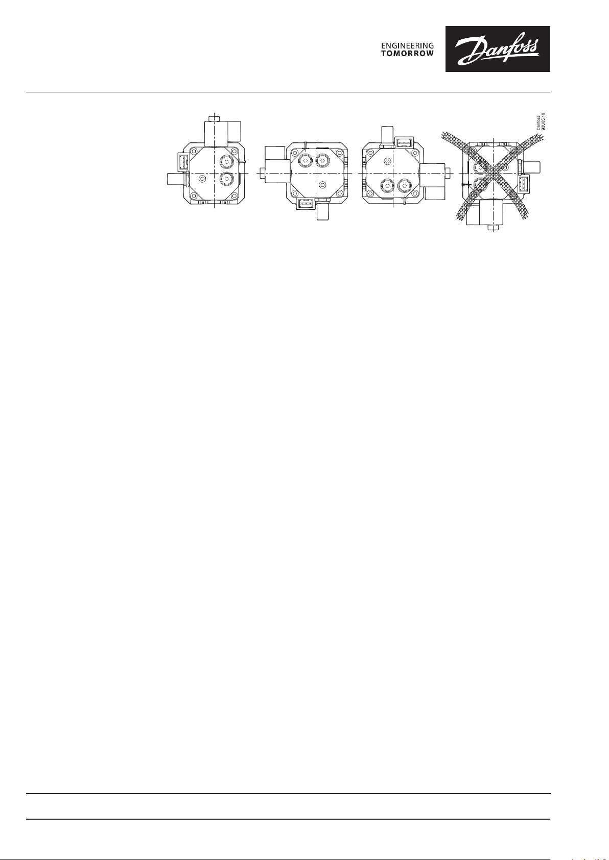
Mounting
Additional documentation on burner components is available on http://heating.danfoss.com/
.danfoss.com • +45 7488 2222 • E-Mail: heating@danfoss.com
s can accept no responsibility for possible errors in catalogues, brochures and o ther printed material. Danfoss reserves the right to alter its products w ithout notice. This also applies to
ts already on order provided that such alterations can be m ade without subsequential changes being necessary in specications already agreed.
l trademarks in this material are p roperty of the respective companies. Danfoss and al l Danfoss logotypes are trademarks of Danfoss A/S. All rights reser ved.
4 | © Danfoss | DHS-SDBT/DK | 2019.05
VD.DK.L3.02
 Loading...