

Page 1
Data Sheet
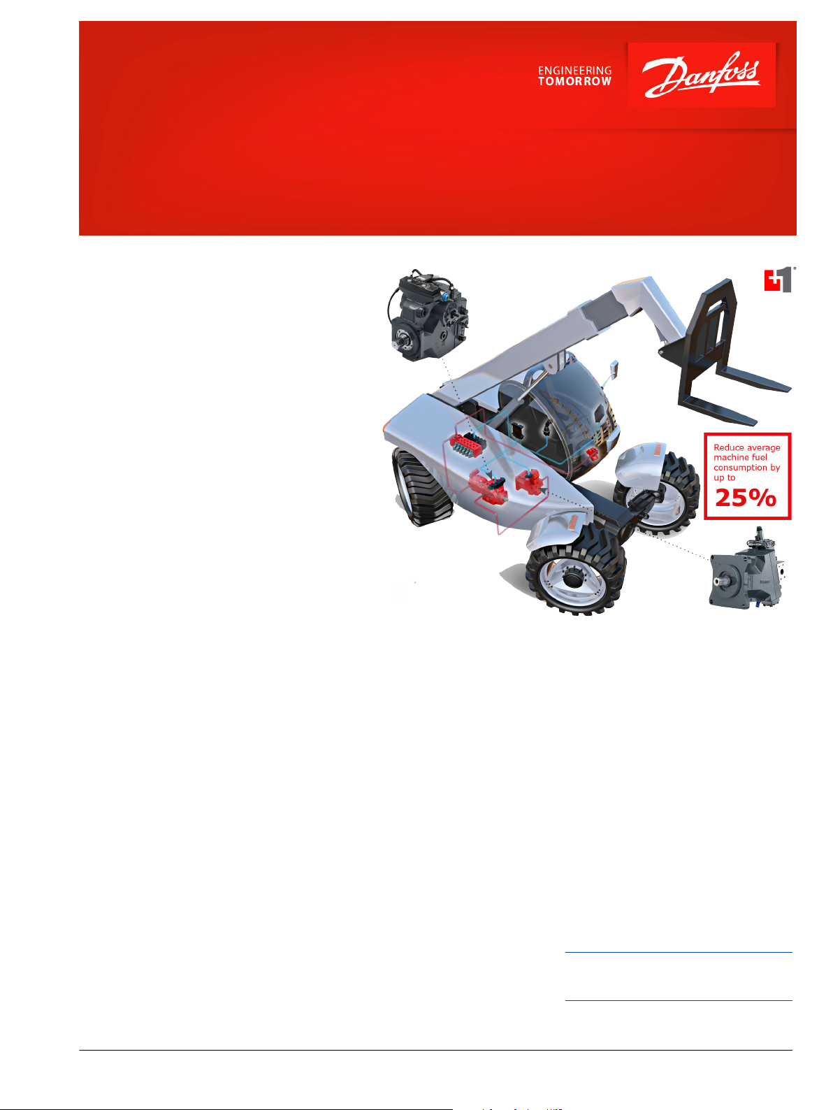
Propel Application Software
Best Point Control (BPC)
Danfoss Best Point Control (BPC) BPC is an innovative
propel application software that can dramatically
increase the efficiency of a machine.
By detecting the power required for the operating
conditions and automatically adjusting the engine
speed to meet optimum efficiency points, BPC adds
instant value to virtually any application.
As a PLUS+1® compliant software block, BPC offers
plug-and-perform integration into existing work
flows.
Regardless of the application, BPC helps to reduce
development time and almost instantly increases
machine control.
Target applications:
•
Telehandler, wheel-loader, dumper, sweeper,
forklift trucks, forestry machines etc.
•
Mobile machines demanding better fuel efficiency
and require a high level of controllability.
Features
Basic functions
•
One drive mode for all operating points
and use cases
•
Machine and engine overspeed
protection
•
Hydrostatic ratio control: intelligent
adjustment of hydraulic pump and
hydraulic motor depending on the load
•
Drive pedal scaling: operator can adjust
the pedal resolution to achieve better
machine controllability and
performance
•
Minimum engine speed adjustment: to
ensure high machine performance and
to provide the oil flow, required for
other sub-systems like work functions
•
Calibration routines to simplify machine
start-up
•
No Engine PPU: accepts J1939 standard
message, no need for additional PPU.
•
Vehicle speed limitation
Flexibility
•
Transmission control: flexible integration
of multiple different final drive solutions
(e.g. 2MT)
•
Modular software design: fit to a variety
of application types
•
Work hydraulic pressure sensor: works in
conjunction with other sub-systems like
Work Function Control
•
Functional safety: designed according to
safety standards for shorter time to
market
Performance and Fuel Economy
•
Best Point Control: depending on the
machine’s load situation, the diesel
engine and the hydrostatic drivetrain
are controlled at their best efficiency
points
•
Vehicle speed control: driver is
controlling the machine movement and
software controls the diesel engine and
hydrostatic ratio
•
Power management functions: electronic
pressure limiter and antistall for more
machine performance
•
Temperature compensation for
predictable performance
Comprehensive technical literature online
at powersolutions.danfoss.com
©
Danfoss | May 2016 AI00000272en-US0102 | 1
Page 2
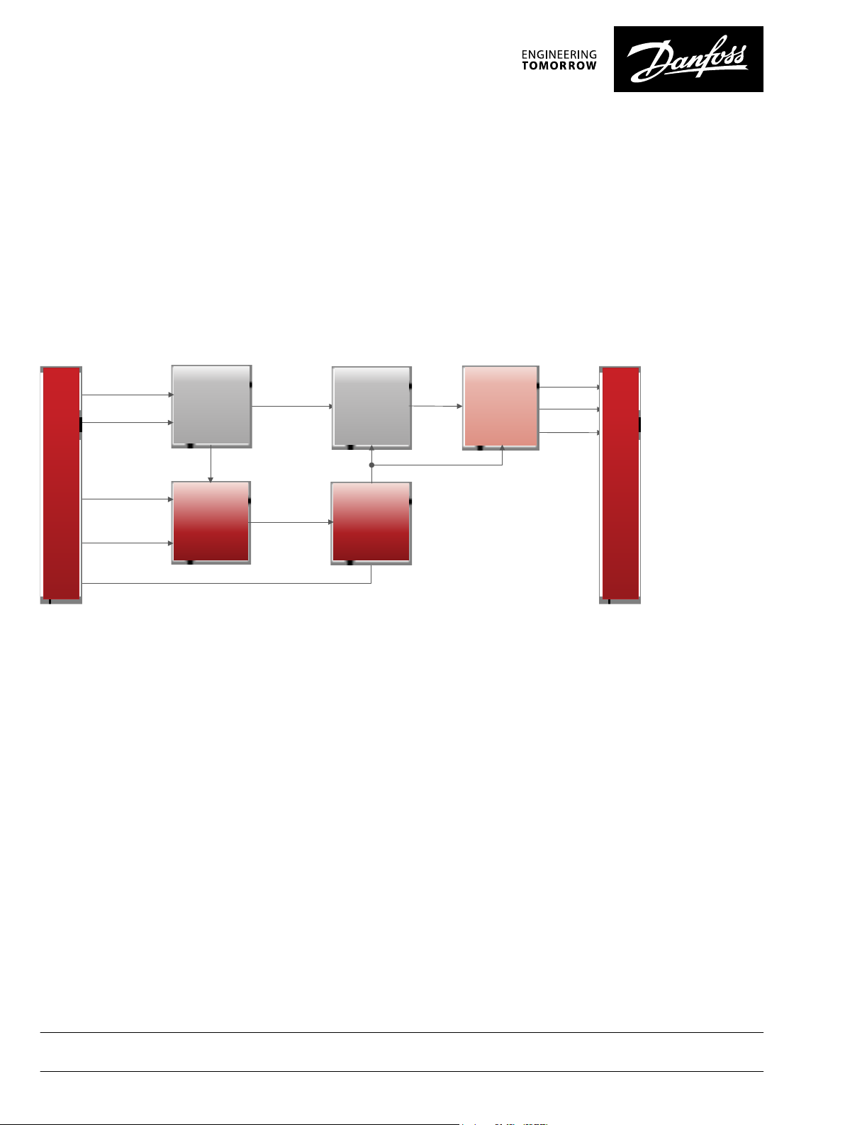
System Requirements
Current Engine
Power on CAN
Delta Vehicle
Speed
Ratio
Request
Vehicle Speed
Request
Engine
Power
Control
Engine Power
Request
Pedal Signal
Hydraulic
Ratio
Control
Vehicle
Speed
Control
External Engine
Speed Request
Ground Speed
External Engine
Power Request
Pump SP
Motor SP
Engine SP
Trans-
mission
Control
Output Conditioning
Drive Control
Transmission
Control
Engine Control
Engine
Speed
Control
Engine
Set Point
Input Conditioning
•
CAN controlled Diesel engine
•
H1 pump with embedded controller incl. swashplate angle
sensor
•
H1 bent axis motor with electric proportional control
•
Final drive configuration e.g. dropbox or dual motor gearbox
BPC Block Diagram
Modular software structure for flexible adaption to customer specific
requirements
Other available Danfoss literature
•
H1 Axial Piston Pumps – Product Line Overview, L1012919
•
H1 Axial Piston Motors – Product Line Overview, L1019304
System Inputs and Outputs
The following inputs and outputs to be considered for a typical
BPC baseline configuration
•
Drive direction switch (FNR) optional via CAN
•
Drive pedal (redundant)
•
Drive enable optional via CAN
•
Manual engine speed setpoint
•
Drive pedal scaling
•
Inch pedal (redundant)
•
Park brake switch
•
Seat switch
•
CAN connection to the engine controller, CAN messages
according J1939
•
Engine speed signal, optional via CAN
•
Hydro motor speed signal
•
Pump control (pre-configured on embedded controller)
•
Hydro motor proportional control
•
Park Brake control
•
Feedback signal Park Brake released
•
Work hydraulic pressure sensor
Danfoss can accept no responsibility for possible errors in catalogues, brochures and other printed material. Danfoss reserves the right to alter its products without notice. This also applies to products
already on order provided that such alterations can be made without changes being necessary in specifications already agreed.
All trademarks in this material are property of the respective companies. Danfoss and the Danfoss logotype are trademarks of Danfoss A/S. All rights reserved.
2 | © Danfoss | May 2016 AI00000272en-US0102
 Loading...