

Data sheet
Flow and temperature controller with integrated control valve,
WE-version (PN 25)
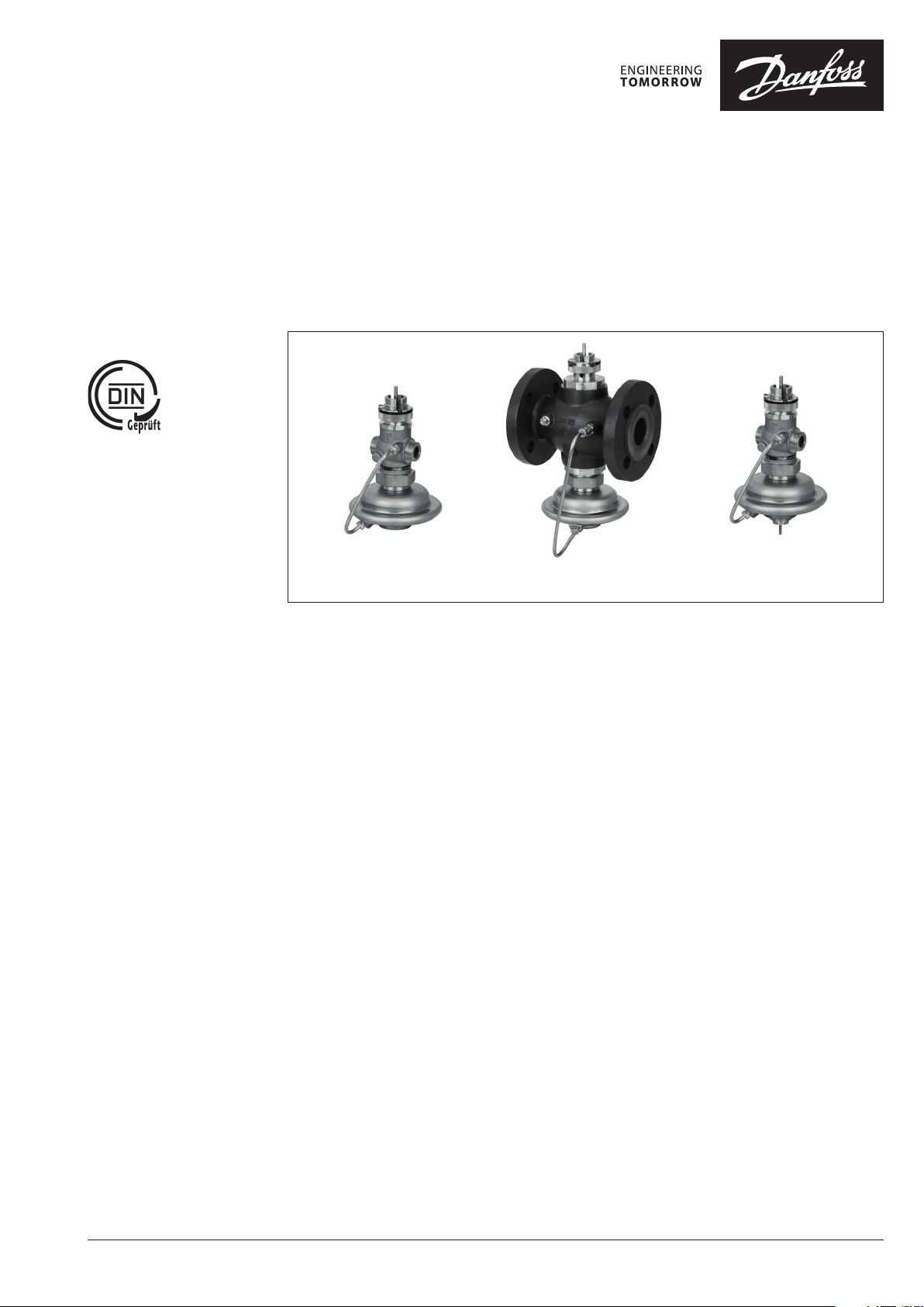
AVQM-WE - f low controller with integrated control valve
AVQMT-WE - f low and temperature controller with integrated control valve
Description
AVQM-WE
DN 15-25
AVQM-WE is a self-acting flow controller with
integrated control valve primarily for use in
district heating systems. The controller closes
when set max. flow is exceeded.
AVQMT-WE is a self-acting flow and temperature
controller with integrated control valve primarily
for use in district heating systems. The controller
closes on rising temperature or when set max.
flow is exceeded.
All controllers have special designed (pressure
relieved) control valve insert.
AVQM-WE controller can be combined with
Danfoss electrical actuators AMV(E) (and
controlled by ECL electronic controllers).
AVQMT-WE controller can be combined with
Danfoss electrical actuators AMV(E) (and
controlled by ECL electronic controllers) and with
AVT or STM thermostatic actuators.
The controllers have a control valve with
adjustable flow restrictor, connection neck
for electrical actuator, connection neck for
thermostat (AVQMT-WE only), and an actuator
with one control diaphragm.
AVQM-WE and AVQMT-WE are used together
with Danfoss electrical actuators:
- AMV 150
- AMV(E) 10 1) / AMV(E) 20 / AMV(E) 30
- AMV(E) 13 1) / AMV(E) 23 / AMV(E) 33 with
spring return function
- AMV 20 SL / AMV 23 SL / AMV 30 SL with stroke
limitation
1)
AMV 150 / AMV(E) 10 / AMV(E) 13 can be combined with D N 15
controller only.
1)
AVQM-WE
DN 32-50
AVQMT-WE
DN 15-25
AVQM(T)-WE combined with AMV(E) 13,
AMV(E) 23 (SL) or AMV(E) 33 (SL) has been
approved according to DIN 32730.
The controllers combined with AVT and STM
thermostats are type-tested acc. to EN 14597.
Controllers combined with STM thermostats
protect systems against exceeding temperatures.
Applications:
- District heating systems acc. to DIN 4747
- Heating systems acc. to EN 12828 (DIN 4751)
and EN 12953-6 (DIN 4752)
- Water heating systems for drinking and
industrial waters acc. to DIN 4753
Main data:
• DN 15-50
• kVS 2.5-25 m3/h
• PN 25
• Setting ranges:
- AVT thermostat:
−10 … 4 0 °C / 20 … 70 °C / 40 … 90 °C / 60 … 110 °C
and
10 … 45 °C / 35 … 70 °C / 60 …
- STM monitor
20
…
75 °C / 40
• Flow restrictor ∆p: 0.2 bar
• Temperature:
- Circulation water / glycolic water up to 30%:
2
…
150 °C
• Connections:
- Ext. thread (weld-on, thread and flange
tailpieces)
- Flange
• Flow and return mounting.
…
95 °C / 30
100 °C / 85
…
110 °C
…
125 °C
© Danfoss | 2021.04 AI083486477108en-AT0501 | 1
Data sheet AVQM(T)-WE, (PN 25)
Ordering
Example 1 AVQM-WE controller:
Flow controller with integrated
control valve; DN 15; kVS 2.5;
PN 25;
flow restrictor Δp 0.2 bar;
T
150 °C
; ext. thread
max
- 1× AVQM-WE DN 15 controller
Code No: 003H7080
Option:
- 1× Weld-on tailpieces
Code No: 003H6908
The controller will be delivered
completely assembled, inclusive
impulse tube bet ween valve and
actuator. Electrical actuator AMV(E)
must be ordered separately.
Example 2 AVT (or STM) / AVQMT-WE
controller:
Flow and temperature controller
with integrated control valve,
DN 15; kVS 2.5; PN 25; setting range
40 … 90 °C; flow restrictor Δp 0.2 bar;
T
150 °C; ext. thread
max
- 1× AVQMT-WE DN 15 controller
Code No: 003H7084
- 1× AVT thermostatic actuator,
40 … 90 °C
Code No: 065-0598
Option:
- 1× Weld-on tailpieces
Code No: 003H6908
The controller AVQMT-WE will be
delivered completely assembled,
inclusive impulse tube between
valve and actuator. Thermostatic
actuator AVT will be delivered
separately. Electrical actuator
AMV(E) must be ordered separately.
In case of safety temp. monitoring
STM should be ordered instead of
AV T.
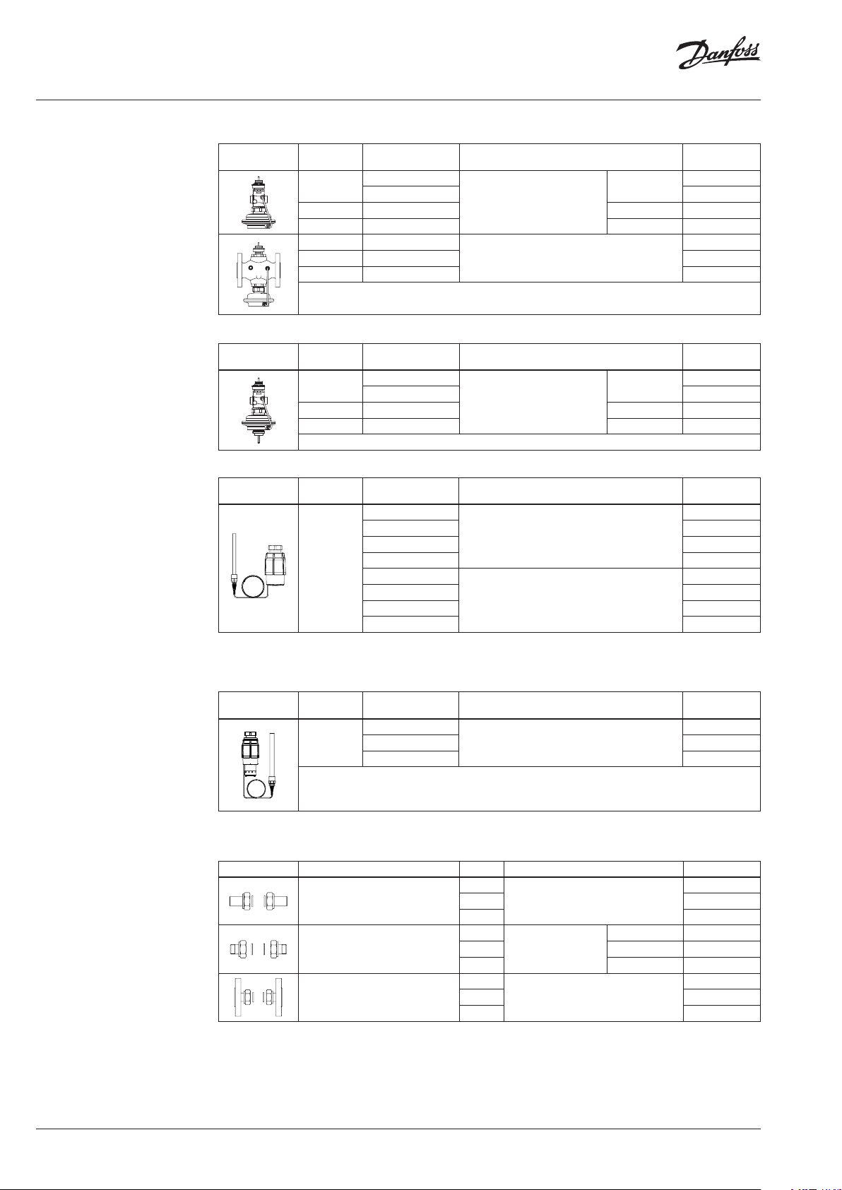
AVQM-WE Controller
Picture
DN
(mm)
15
20 6.3 G 1 A 003H7082
25 8.0 G 1¼ A 003H7083
32 12. 5
40 20
50 25
(m3/h)
AVQMT-WE Controller
Picture
DN
(mm)
15
20 6.3 G 1 A 003H7086
25 8.0 G 1¼ A 003H7087
(m3/h)
AVT Thermostatic actuator
Picture For valves
1)
conic male threa d EN 10226 -1
2)
without imme rsion pocket
DN 15-2 5
Setting range
–10 … +40
20 … 70 065-0597
40 … 90 065-0598
60 … 110 065-0599
10 … 45
35 … 70 065-0605
60 … 100 065-0606
85 … 12 5 065-0607
STM Safety temperature monitor (actuator)
Picture For valves
DN 15-2 5
1)
conic male threa d EN 10226 -1
Limit range
30 … 11 0
20 … 75 065-0609
40 … 95 065-0610
k
VS
2.5
4.0 003H7081
k
VS
2.5
4.0 003H7085
(°C)
(°C)
Cylindr. ext. thread acc. to
Cylindr. ext. thread acc. to
Temperature sensor with brass immersion
Temperature sensor with brass immersion
Connection Code No.
G ¾ A
ISO 228/1
Flanges PN 25, acc. to EN 1092-2
Connection Code No.
G ¾ A
ISO 228/1
pocket, length, connection
170 mm, R ½
255 mm, R ¾
pocket, length, connection
210 mm, R ¾
1)
1) 2)
1)
003H7080
003H7088
003H7089
003H7090
003H7084
Code No.
065-0596
065-0604
Code No.
065-0608
Accessories for valves
Picture Type designation DN Connection Code No.
Weld-on tailpieces
External thread tailpieces
Flange tailpieces
15
20 003H6909
25 00 3H6910
15
Conical ex t. thread
20 R ¾ 003H6903
25 R 1 003H6904
15
20 003H6 916
25 0 03H6 917
acc. to
EN 10226-1
Flanges PN 25, acc. to EN 1092-2
-
R ½ 003H6902
003H6908
003H6 915
2 | AI083486477108en-AT0501 © Danfoss | 2021.04
Data sheet AVQM(T)-WE, (PN 25)
Ordering (continuous)
Example 3 STM / AVT / AVQMT-WE controller:
Flow and temperature controller
with safety temperature monitor
and integrated control valve,
DN 15, kVS 2.5; PN 25; setting range
40 … 90 °C; limit range 30 … 110 °C;
flow restrictor Δp 0.2 bar;
T
150 °C; ext. thread
max
- 1× AVQMT-WE DN 15 controller
Code No: 003H6787
- 1× AVT thermostatic actuator,
40 … 90 °C
Code No: 065-0598
- 1× STM monitor, 30 … 110 °C
Code No: 065-0608
- 1× K2 Combination piece
Code No: 003H6855
Option:
- 1× Weld-on tailpieces
Code No: 003H6908
The controller AVQMT-WE will be
delivered completely assembled,
inclusive impulse tube between
valve and actuator. Combination
piece K2, thermostats AVT and STM
will be delivered separately.
Electrical actuator AMV(E) must be
ordered separately.
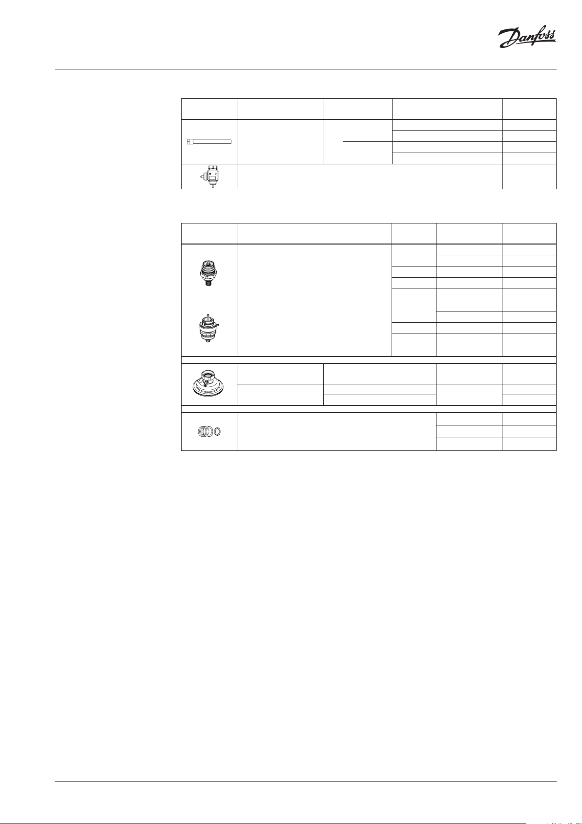
Accessories for thermostats
Picture Type designation PN
Immersion pocket 25
Combination piece K2 003H6855
1)
Not for AVT the rmostatic actuator code numb ers: 065-0604, 065-0605, 065-0606, 065-0607
For
thermostats
AVT
STM
Material Code No.
Stainless steel, mat. No. 1.4571 06 5-4 415
Stainless steel, mat. No. 1.4435 065 -4417
Service kits
Picture Type designation DN
15
Valve insert
Control valve insert
Type designation For controller
Actuator
1)
1)
AVQM-WE
AVQMT-WE 003H6843
20 6.3 003H6865
25 8.0 003H6866
32 / 40 / 50 12.5 / 20 / 25 003H6868
15
20 6.3 003H6990
25 8.0 003H6991
32 / 40 / 50 12.5 / 20 / 25 0 03H6992
Brass 06 5-4 414
Brass
k
VS
(m3/h)
2.5 003H6863
4.0 003H6864
2.5 003H6988
4.0 003H6989
∆p settin range
(bar)
0.2
065- 4416
Code No.
Code No.
003H6 841
1)
1)
1)
1)
Housing of sensor stuffing box
1)
For AVQM-WE and AVQMT-WE controler s
for sensors
AVT R ½ 065-4420
AVT R ¾ 065- 4421
AI083486477108en-AT0501 | 3© Danfoss | 2021.04
Data sheet AVQM(T)-WE, (PN 25)
Technical data
Valve
Nominal diameter DN 15 20 25 32 40 50
kVS value of dp controller
Range of
max.
flow setting
p
bar
MCV
= 0.2
Avalib le p required for Q
Q
m3/h
min
Q
max
2)
max
bar 0.6 0.6 0.5 0.5 0.8 0.8/0.61)0.8/0.6
2.5 4.0 6.3 8.0 12. 5 16/2 01)20/25
0.07 0. 07 0.16 0.2 0.4 0.8 0.8
1.6 2.4 3.5 4.5 10 10.5/121)12/ 14
Stroke mm 5 7 10
Control valve authority 1 (100%) in the range of flow setting
Control characteristic Logarithmic
Cavitation factor z ≥ 0.6 ≥ 0.55 ≥ 0.5
Leakage acc. to standard IEC 534 % of k
VS
≤ 0.02 ≤ 0.05
Nominal pressure PN 25
Min. differential pressure
Max. differential pressure 20 16
bar
see remark
2)
Medium Circulation water / glycolic water up to 30%
Medium pH Min. 7, max. 10
Medium temperature
Connections
valve External thread Flange
tailpieces Weld-on, ex ternal thread and flange ⁄
o
C 2 … 150
Materials
Ductile iron
Valve body Red bronze CuSn5ZnPb (Rg5)
EN-GJS-400-18-LT
(GGG 40.3)
Valve seat Stainless steel, mat. No. 1.4571
Valve cone Dezincing free brass CuZn36Pb2As
Sealing DP, CV EPDM
Pressure relieve system
Control valve insert
Valve insert
Piston
Note:
DP - diff. pressu re controller, MCV - control valve
1)
Flanged version
2)
For flows smal ler than Q
->
p
max
min
2
Q
p
MCV
k
VS
1)
1)
1)
4 | AI083486477108en-AT0501 © Danfoss | 2021.04
Data sheet AVQM(T)-WE, (PN 25)
Technical data (continuous)
Actuator
Typ e AVQM -WE, AVQMT-WE
Actuator size cm
Nominal pressure PN 25
Flow restrictor diff. pressure bar 0.2
Materials
Housing
Upper housing of actuator Stainless steel, mat. No.1.4301
Lower housing of actuator Dezincing free brass CuZn36Pb2As
Diaphragm EPDM
Impulse tube Copper tube Ø 6 × 1 mm
2
54
AVT Thermostatic actuator
Setting range X
s
°C
Time constant T acc. to EN 14597 s max. 50 (170 mm, max. 30 (255 mm)
Gain K
s
mm/°K
Max. adm. temperature at sensor 50 °C above maximum setpoint
Max. amb. temperature at thermostat °C 0 … 70
Nominal pressure sensor
Nominal pressure immerison pocket
PN 25
Capillary tube length 5 m (170 mm), 4 m (255 mm)
Materials
Temperature sensor Cooper
Ms design Brass, nickel-plated
Immersion pocket
1)
Stainless steel design Mat. No. 1.4571 (170 mm)
Handle for temp. setting Polyamide, glass fiber-reinforced
Scale carrier Polyamide
1)
for senso r 170
−10 … 40 / 20 … 70 / 40 … 90 / 60 … 110
10 … 45 / 35 … 70 / 60 … 100 / 85 … 125
0.2 (170 mm); 0.7 (255 mm)
STM Safety temperature monitor (actuator)
Limit range X
s
Time constant T acc. to EN 14597 s max. 100
Gain K
s
Max. adm. temperature at sensor 80 °C above maximum setpoint
Max. amb. temperature at thermostat °C 0 … 70
Nominal pressure sensor
Nominal pressure immerison pocket
Capillary tube length m 5
Materials
Temperature sensor Cooper
Immersion pocket
Ms design Brass, nickel-plated
Stainless steel design mat. No. 1.4435
Handle for temp. setting Polyamide, glass fiber-reinforced
Scale carrier Polyamide
°C 20 … 75 / 40 … 95 / 30 … 110
mm/°K 0.3
PN 25
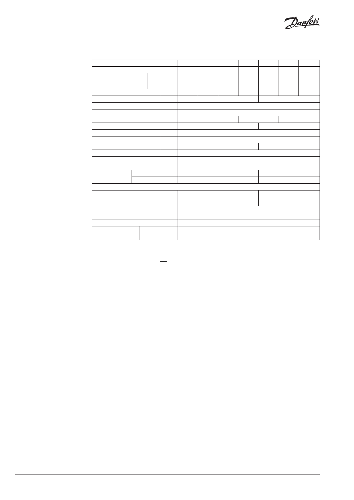
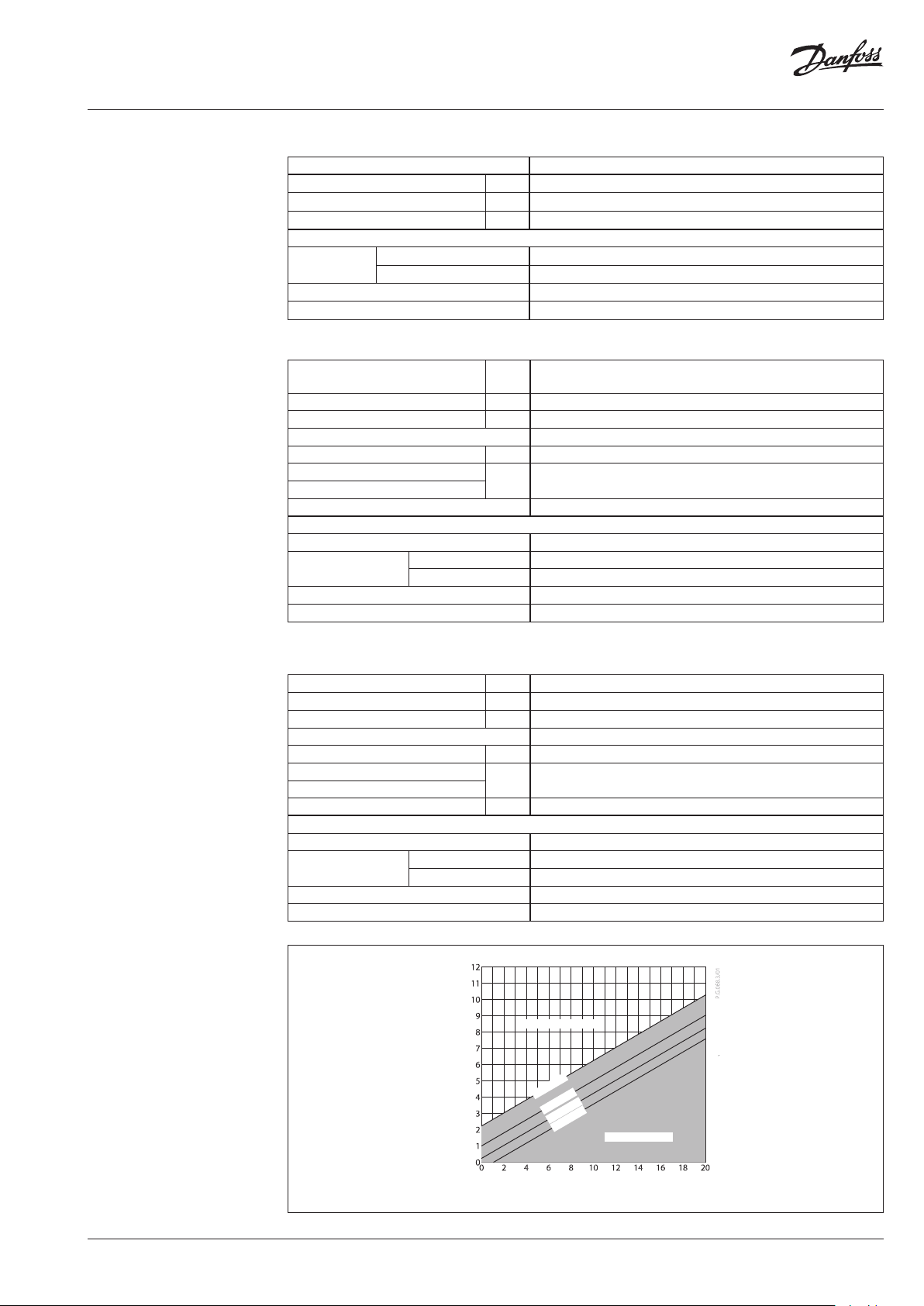
No Cavita tion noise
T=150 °C
T=130 °C
T=110 °C
T=70 ° C
Manometric Pressure downstrem [bar]
Cavitation noise
Cavitation area for cavitation factor z = 0.6
Manometric Pressure upstrem [bar]
AI083486477108en-AT0501 | 5© Danfoss | 2021.04

Data sheet AVQM(T)-WE, (PN 25)
Application principles
Combinations
AVQM-WE / AMV(E)
- Flow controller with electrical actuator
AVT / AVQMT-WE / AMV(E)
- Flow and temperature controller with
electrical actuator
STM / AVQMT-WE / AMV(E)
- Flow controller with safety temperature
monitor and electrical actuator
STM / AVT / AVQMT-WE / AMV(E)
- Flow and temperature controller
with safety temperature monitor and
electrical actuator
6 | AI083486477108en-AT0501 © Danfoss | 2021.04

Data sheet AVQM(T)-WE, (PN 25)
Installation positions
Flow and temperature controller with integrated
control valve (with AVT or STM)
Up to medium temperature of 100 °C the
controllers can be installed in any position.
Electrical actuator
Note!
Installation positions for electrical actuators AMV(E) have
to be observed as well. Please see relevant Data sheet.
Temperature sensor
The place of installation must be chosen in a way
that the temperature of the medium is directly
taken without any delay. Avoid overheating of
temperature sensor. The temperature sensor
must be immersed into the medium in its full length.
Temperature sensors 170 mm R½
- The temperature sensor may be installed in
any position.
For higher temperatures the controllers have
to be installed in horizontal pipes only, with a
pressure and temperature actuator oriented
downwards.
Temperature sensor 255 mm R¾
- The temperature sensor must be installed as
shown on the picture.
Pressure temperature
diagram
② EN-GJS -400-18-LT (GGG 40. 3) PN 25
① CuSn5ZnPb (Rg5) PN 25
Maximum allowed operating pressure as a function of medium temperature (according to EN 1092-3).
AI083486477108en-AT0501 | 7© Danfoss | 2021.04

Data sheet AVQM(T)-WE, (PN 25)
Design
1. Control valve insert
2. Adjustable flow restrictor
3. Valve body
4. Valve insert
5. Pressure relieved valve cone
6. Valve stem
7. Built-in spring for flow rate
control
8. Control drain
9. Control diaphragm
10. Union nut
11. Impulse tube
12. Upper casing of diaphragm
13. Lower casing of diaphragm
14. Thermostat AVT, STM
15. Thermostat stem
16. Bellows
17. Setting spring for
temperature control
18. Handle for temperature
setting, prepared for sealing
19. Scale carrier
20. Capillary tube
21. Flexible protected pipe (at
255mm only)
22. Temperature sensor
23. Immersion pocket
24. Sensor stuffing box
25. Housing of sensor stuffing
box
26. Safety spring
AVT 255
AV T 170
STM
AVQM-WE
STM
AVT / AVQMT-WE
8 | AI083486477108en-AT0501 © Danfoss | 2021.04

Data sheet AVQM(T)-WE, (PN 25)
Function Flow and temperature controller with integrated
control valve (AVQM-WE, AVQMT-WE)
Flow volume causes pressure drop across
the adjustable flow restrictor. Resulting
pressures are being transferred through the
impulse tubes and/or control drain in the
actuator stem to the actuator chambers and
act on control diaphragm for flow control.
The flow restrictor diff. pressure is controlled
and limited by means of built-in spring for
flow control. Control valve closes on rising
differential pressure and opens on falling
differential pressure to control max flow.
Additionally the electrical actuator will
operate from zero to set max. flow according
to the load.
Safety Temperature Monitor (STM)
- Function
The safety temperature monitor is
proportional temperature controller which
controls temperature and protects the system
against exceeding temperatures. The valve
cone is soft sealed and pressure relieved.
In case the temperature at the temperature
sensor exceeds the adjusted set point, safety
temperature monitor interrupts energy
supply by closing the valve. As soon as the
temperature at the temperature sensor drops,
the valve opens automatically.
Handle for limit setting can be sealed.
- Extended safety function
If there is a leakage in the area of the
temperature sensor, the capillary tube, or the
thermostat, the valve closes by a safety spring
in the safety thermostat. In this case safety
temperature monitor (actuator) must be
replaced.
- Physical Function Principle
The safety temperature monitor operates
in accordance with the liquid expansion
principle. The temperature sensor, the
capillary tube and the bellows are filled with
liquid. As the temperature at the temperature
sensor rises, the liquid expands, the
thermostat stem moves out and closes the
valve.
Temperature Controller (AVT)
- Function
By increasing of medium temperature control
valve cone moves towards the seat (valve
closes), by decreasing of medium temperature
valve cone moves away from the seat (valve
opens).
Handle for temperature setting can be sealed.
- Physical Function Principle
Medium temperature changes cause pressure
changes in temperature sensor. Resulting
pressure is being transferred through the
capillary tube to the bellows. Bellows moves
thermostat stem and opens or closes the
valve.
Settings
Flow setting
Flow setting is being done by the adjustment of
the flow restrictor position. The adjustment can
be performed on the basis of flow adjustment
diagram (see relevant instructions) and/or by the
means of heat meter.
Temperature setting (AVT)
Temperature setting is being done by the
adjustment of the setting spring for temperature
control. The adjustment can be done by means
of handle for temperature setting and/or
temperature indicators.
Limit setting (STM)
Limit setting is being done by the adjustment of
the setting spring for temperature control. The
adjustment can be done by means of handle for
limit setting and/or temperature indicators.
AI083486477108en-AT0501 | 9© Danfoss | 2021.04

Data sheet AVQM(T)-WE, (PN 25)
Adjustment diagram Temperature setting
Relation between scale numbers 1-5 and closing
temperature.
Note: The values given are approximate
AVT Thermostat ... 170 mm
AVT Thermostat ... 255 mm
Note:
STM Safety temperature monitor (actuator):
temperature scale is already written on the product
10 | AI083486477108en-AT0501 © Danfoss | 2021.04

Data sheet AVQM(T)-WE, (PN 25)
Dimensions
155
121
AMV(E) 10 +
AVQM-WE (DN 15)
121
H*
H*
AMV(E) 13 +
AVQM-WE (DN 15)
Typ e DN 15 20 25 32 40 50
AMV(E) 10
AVQM -WE H*
L
1
H
AM V(E) 13 295 - - - - -
AMV(E) 2./3. 305 305 308 386 386 386
AM V 150 293 - - - - -
L
155
AMV(E) 2./3. +
AVQM-WE (DN 15-25)
292 - - - - -
mm
1
H
92
H*
H*
AMV 150 +
AVQM-WE (DN 15-25)
H*
AMV(E) 2./3. +
AVQM-WE (DN 32-50)
L
1
H
H
Ø125
AVQM (DN 15-25)
Typ e DN 15 20 25 32 40 50
AVQM -WE
L
H 109 109 109 15 0 150 15 0
H
1
Valve weight kg 3.0 3.0 3.2 10.3 11.8 13.9
H
65 70 75 180 200 230
mm
76 76 79 101 101 101
AVT / AVQMT-WE / AMV(E)
DN 15 20 25
AMV/ E 10
H
AM V/E 13 445 - -
AMV/E 2.,/3. 455 455 458
Ø125
AVQM (DN 32-50)
442 - -
mm
H
H
Ø125
AVQMT (DN 15-25)
Typ e DN 15 20 25
AVQMT -WE
H
STM / AVQMT-WE / AMV(E)
DN 15 20 25
AMV/ E 10
H
AM V/E 13 489 - -
AMV/E 2.,/3. 499 499 502
L
H 131 131 131
H
1
65 70 75
mm
76 76 79
486 - -
mm
AI083486477108en-AT0501 | 11© Danfoss | 2021.04

Data sheet AVQM(T)-WE, (PN 25)
Adjustment diagram Temperature setting
Relation between scale numbers 1-5 and closing
temperature.
Note: The values given are approximate
AVT Thermostat ... 170 mm
AVT Thermostat ... 255 mm
Note:
STM Safety temperature monitor (actuator):
temperature scale is already written on the product
12 | AI083486477108en-AT0501 © Danfoss | 2021.04

Data sheet AVQM(T)-WE, (PN 25)
Dimensions
155
121
AMV(E) 10 +
AVQM-WE (DN 15)
121
H*
H*
AMV(E) 13 +
AVQM-WE (DN 15)
Typ e DN 15 20 25 32 40 50
AMV(E) 10
AVQM -WE H*
L
1
H
AM V(E) 13 295 - - - - -
AMV(E) 2./3. 305 305 308 386 386 386
AM V 150 293 - - - - -
L
155
AMV(E) 2./3. +
AVQM-WE (DN 15-25)
292 - - - - -
mm
1
H
92
H*
H*
AMV 150 +
AVQM-WE (DN 15-25)
H*
AMV(E) 2./3. +
AVQM-WE (DN 32-50)
L
1
H
H
Ø125
AVQM (DN 15-25)
Typ e DN 15 20 25 32 40 50
AVQM -WE
L
H 109 109 109 15 0 150 15 0
H
1
Valve weight kg 3.0 3.0 3.2 10 .3 11.8 13. 9
H
65 70 75 180 200 230
mm
76 76 79 101 101 101
AVT / AVQMT-WE / AMV(E)
DN 15 20 25
AMV/ E 10
H
AM V/E 13 445 - -
AMV/E 2.,/3. 455 455 458
Ø125
AVQM (DN 32-50)
442 - -
mm
H
H
Ø125
AVQMT (DN 15-25)
Typ e DN 15 20 25
AVQMT -WE
H
STM / AVQMT-WE / AMV(E)
DN 15 20 25
AMV/ E 10
H
AM V/E 13 489 - -
AMV/E 2.,/3. 499 499 502
L
H 131 131 131
H
1
65 70 75
mm
76 76 79
486 - -
mm
AI083486477108en-AT0501 | 13© Danfoss | 2021.04

Data sheet AVQM(T)-WE, (PN 25)
14 | AI083486477108en-AT0501 © Danfoss | 2021.04

Data sheet AVQM(T)-WE, (PN 25)
AI083486477108en-AT0501 | 15© Danfoss | 2021.04

Data sheet AVQM(T)-WE, (PN 25)
© Danfoss | DCS-S/SI | 2021.0416 | AI083486477108en-AT0501
 Loading...