

Danfoss AVQM Series, AVQMT Series Instructions Manual
Instructions
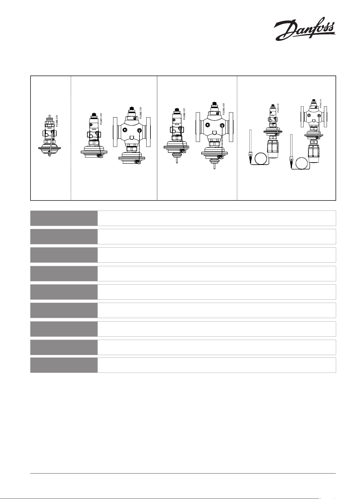
AVQM, AVQMT – PN 16, 25 / DN 15-50
AVQM (PN 16) AVQM (PN 25) AVQMT (PN 25) AVQMT/AVT (PN 25)
DN 15-32 DN 15-50 DN 32-50 DN 15-50 DN 32-50 DN 15-50 DN 32-50
∆p = 0.2 ∆p = 0.2 ∆p = 0.2 ∆p = 0.2 ∆p = 0.2 ∆p = 0.2 ∆p = 0.2
ENGLISH
DANSK
DEUTSCH
ESPAÑOL
SLOVENŠČINA
POLSKI
MAGYAR
SRPSKI
ITALIANO
Flow (and temperature) controller with integrated control
valve AVQM, AVQMT
Flow- (og temperatur-)regulator med indbygget motorventil
AVQM, AVQMT
Volumenstrom (und Temperatur-) Regler mit Motorstellventil
AVQM, AVQMT
Regulador de caudal (y temperatura) con válvula de control
integrada AVQM, AVQMT
Regulator pretoka (in temperature) z regulacijskim ventilom
AVQM, AVQMT
Regulator przepływu (i temperatury) z zaworem
regulacyjnym AVQM, AVQMT
Térfogatáram(és hőmérséklet) szabályozó, motoros
szabályozó-szeleppel egybeépítve AVQM, AVQMT
Uputstvo AVQM, AVQMT-PN 16, 25/DN 15-50 grejanje.danfoss.com Strana 21
Flow (and temperature) controller with integrated control
valve AVQM, AVQMT
www.danfoss.com Page 7
www.danfoss.dk Side 9
www.danfoss.de Seite 11
www.danfoss.es Página 13
www.danfoss.si Stran 15
www.danfoss.pl Strona 17
www.danfoss.hu Oldal 19
www.danfoss.it Pagina 23
73695050 DH -SMT/SI VI.DB .T3.3F © Dan foss 02/2011 1
❾
AVQM PN 16
AVQM PN 25
AVQM PN 16
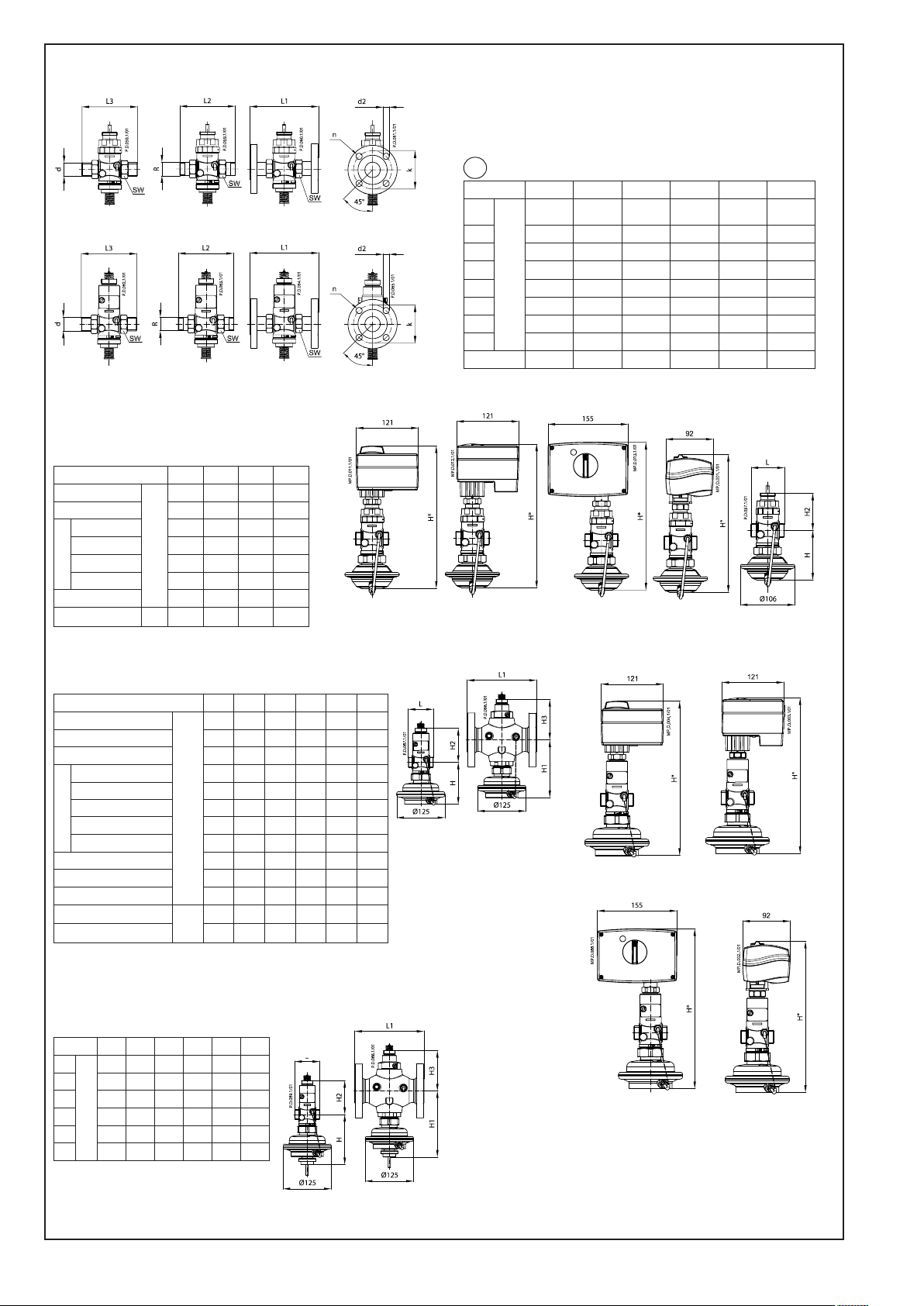
DN 15 20 25 32
L
H 97 97 97 97
AMV(E) 10 277 – – –
AMV(E) 13 280 – – –
H*
AMV(E) 2./3. 290 290 293 294
AMV 150 278 – – –
H2 73 73 76 77
Valve weight kg 1,9 1,9 2,0
65 70 75 100
mm
AMV(E) 10 +
AVQM (DN 15)
T1
DN
SW
d
1)
R
2)
L1
mm
L2
L3
k
d
2
n
AMV(E) 13 +
AVQM (DN 15)
15 20 25 32 40 50
32
(G ¾A)
41
(G 1A)
50
(G 1¼A)
63
(G 1¾A)
70
(G 2A)
21 26 33 42 47 60
½ ¾ 1 1 ¼ - 130 150 160 - - 131 144 160 177 - 139 154 159 184 204 234
65 75 85 100 110 125
14 14 14 18 18 18
4 4 4 4 4 4
AMV(E) 2./ 3. +
AVQM (DN 15-32)
AMV 150 +
AVQM (DN 15)
AVQM PN 16
82 (G
2½A)
AVQM PN 25
DN 15 20 25 32 40 50
L
L1 - - - 180 200 230
H 109 109 109 150 150 150
AMV(E) 10 307 - - - - AMV(E) 13 304 - - - - -
H*
AMV(E) 2./3. (thread) 317 317 320 375 375 375
AMV(E) 2./3. (flange) - - - 390 390 390
AMV 150 305 - - - - H1 - - - 150 150 150
H2 88 88 91 105 105 105
H3 - - - 105 105 105
Valve weight (thread)
Valve weight (flange) - - - 10,3 11,8 13,9
3)
65 70 75 100 110 130
mm
3.0 3.0 3.2 5.8 5.9 6.6
kg
AVQMT PN 25
DN 15 20 25 32 40 50
L
65 70 75 100 110 130
L1 - - - 180 200 230
H 131 131 131 172 172 172
mm
H1 - - - 172 172 172
H2 88 88 91 105 105 105
H3 - - - 105 105 105
3)
AVQM PN 25
DN 15-50
AVQM PN 25
DN 32-50
AMV(E) 10 +
AVQM (DN 15)
AMV(E) 2./3. +
AVQM
AMV(E) 13 +
AVQM (DN 15)
AMV 150 +
AVQM (DN 15)
AVQMT PN 25
DN 15-50
2 VI.DB .T3.3F © Dan foss 02/2011 73695050 DH -SMT/SI
AVQMT PN 25
DN 32-50
❶ ❷
AMV(E)
< 100 °C
> 100 °C
❸
❺
④
⑥
❽
①
②
⑤
⑦ ⑧
③
DN L (mm)
15 69
20 74
25 79
32 104
40 114
50 134
②
❹
❻
❿
❼
< 100 °C
> 100 oC
①
②
–
+
①
③
⓫
⓬
①
PN 16
②
PN 25
M
⓮
PN 16
⑥
④
PN 16
⑤
①
②
①
Δp
v
73695050 DH -SMT/SI VI.DB .T3.3F © Dan foss 02/2011 3
PN 25
4 mm
⑦
③
⑧
4 mm
⑤
PN 25
⓭
PN 16 PN 16
PN 25
PN 25
⓯
⑤
⑥
4 mm
⑦
4 mm
④
M
①
M
③
④
②
⑩
⑧
⑨
4 mm
⑪
⑫
4 mm
⑨
PN 16
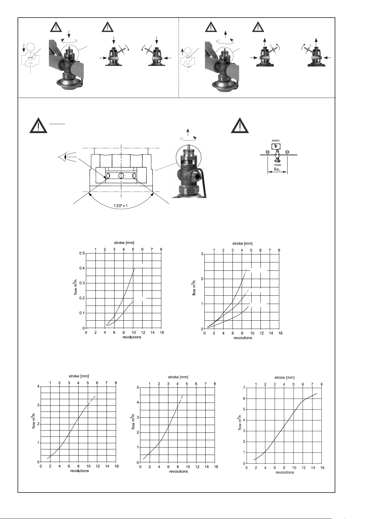
1 = 120°
Δpv:
—
0.5 … 12 bar
_ _ _ 1.0 … 12 bar
kvs 1.0
kvs 0.4
DN 15
kvs 4.0
kvs 2.5
kvs 1.6
DN 32 kvs 10DN 25 kvs 8.0DN 20 kvs 6.3
4 VI.DB .T3.3F © Dan foss 02/2011 73695050 DH -SMT/SI
⓰
PN 25
1 = 360°
1 = 360°
kvs 1.0
kvs 0.4
DN 15
1 = 360°
Δpv:
—
0.5 … 12 bar
_ _ _ 1.0 … 12 bar
kvs 4.0
kvs 2.5
kvs 1.6
DN 20 kvs 6.3
DN 25 kvs 8.0
DN 32 kvs 12.5
73695050 DH -SMT/SI VI.DB .T3.3F © Dan foss 02/2011 5
⓰
PN 25
1 = 360°
1 = 360°
DN 40 kvs 16, 20
1 = 360°
Δpv:
—
0.5 … 12 bar
_ _ _ 1.0 … 12 bar
DN 50 kvs 20, 25
6 VI.DB .T3.3F © Dan foss 02/2011 73695050 DH -SMT/SI
ENGLISH
Safety Notes
Prior to assembly and commissioning to
avoid injury of persons and damages of
the devices, it is absolutely necessary
carefully read and observe these instructions.
Necessary assembly, start-up, and
maintenance work must be performed
only by qualified, trained and authorized
personnel.
Prior to assembly and maintenance work
on the controller, the system must be:
- depressurized,
- cooled down,
- emptied and
- cleaned.
Please comply with the instructions of the
system manufacturer or system operator.
to
Definition of Application
The controller is in combination with
electrical actuators (AMV(E) used for flow
and temperature control of water and
water glycol mixtures for heating, district
heating and cooling systems.
AVQM PN 16 could be combined with
electrical actuators AMV(E) 10/13 (DN15
only), AMV(E) 20/23, AMV 20/23 SL,
AMV(E) 30/33, AMV 30, AMV 150.
AVQM(T) PN 25 could be combined
with electrical actuators AMV(E) 10/13
(DN15 only), AMV(E) 20/23, AMV 20/23 SL,
AMV(E) 30/33, AMV 30, AMV 150.
AVQMT PN 25 could be combined with
temperature actuator AVT or safety
temperature monitor (actuator) STM.
The technical parameters on the product
labels determine the use.
Assembly
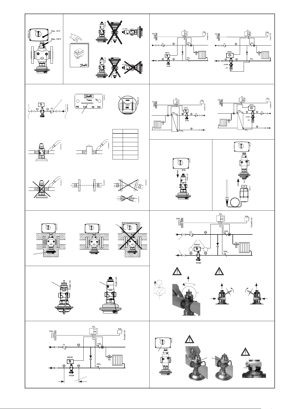
Admissible Temperatures ❶
Admissible Installation Positions ❷
Medium temperatures up to 100 °C:
- Can be installed in any position,
except
with electrical actuator oriented
downwards.
Medium temperatures > 100 °C:
- Installation permitted only in horizontal
pipelines with the electrical actuator
oriented upwards.
Other details:
See instructions for electrical actuator
AMV(E). In case of AVQMT controller see
instructions for temperature actuator AVT
or safety temperature monitor (actuator)
STM as well.
Installation Location and
Installation Scheme
AVQM(T) return mounting ❸
AVQM(T) flow mounting ❹
Valve Installation ❺
1. Clean pipeline system prior to assembly.
2. The installation of a strainer ① in
front of the controller is strongly
recommended.
3. Install valve
• The flow direction indicated on the
product label ② or on the valve ③
must be observed.
• The valve with mounted weld-on
tailpieces may only be spot welded to
the pipeline ④.
The weld-on tailpieces may be welded
only without the valve and seals! ⑤⑥
If these instructions are not observed,
high welding temperatures may
destroy the seals.
• Flanges ⑦ in the pipeline must be in
parallel position and sealing surfaces
must be clean and without any
damage.
Tighten screws in flanges crosswise
in 3 steps up to the maximum torque
(50 Nm).
4. Caution:
Mechanical loads of the valve body by the
pipelines are not permitted ⑧.
Mounting of electrical actuator ❻
Place electrical actuator AMV(E) on the
valve and tighten union nut with wrench
SW 32.
Torque 25 Nm.
Other details:
See instructions for electrical
actuator AMV(E).
Mounting of temperature
actuator ❼
(relevant only at AVQMT controllers)
Place temperature actuator AVT or STM at
the diaphragm and tighten union nut with
wrench SW 50.
Torque 35 Nm.
Other details:
See instructions for temperature
actuator AVT or STM.
Insulation ❽
For medium temperatures up to 100 °C the
pressure actuator ① may also be insulated.
Insulation of electrical actuator ②
AMV(E) is not allowed.
Dimensions, Weights ❾
1)
Conical ext. thread acc. to EN 10226-1
2)
Flanges PN 25, acc. to EN 1092-2
3)
Other flange dimensions – see table
for tailpieces.
T1
Start-up ❿
Filling the system, first start-up
1. Open valves in the system.
2. Slowly open shut-off devices ① in the
flow pipeline.
3. Slowly open shut-off devices ② in the
return pipeline.
Leak and Pressure Tests
Do not test closed control valve with
pressures of more than 16 bar. Otherwise,
the valve may be damaged.
Pressure tests should be carried out prior
to the installation of the electrical actuator.
This guarantees that the valve is opened.
Before pressure test, open the adjustable
flow restrictor ④⑤ by turning it:
- at PN 16 controller to the left (counter
clockwise) ⑥
- at PN 25 controller to the left
(counter clockwise) ⑦ or to the right
(clockwise) ⑧
Pressure must be gradually
increased at the (+/-)
connection ③.
Non-compliance may cause damages at
the actuator or the valve.
A pressure test of the entire system
must be carried out in accordance with
manufacturer’s instructions.
The maximum test pressure is: 1.5 × PN
PN – see product label!
Putting out of operation
1. Slowly close shut-off devices ① in the
flow pipeline.
2. Slowly close shut-off devices ② in the
return pipeline.
73695050 DH -SMT/SI VI.DB .T3.3F © Dan foss 02/2011 7
Settings
No
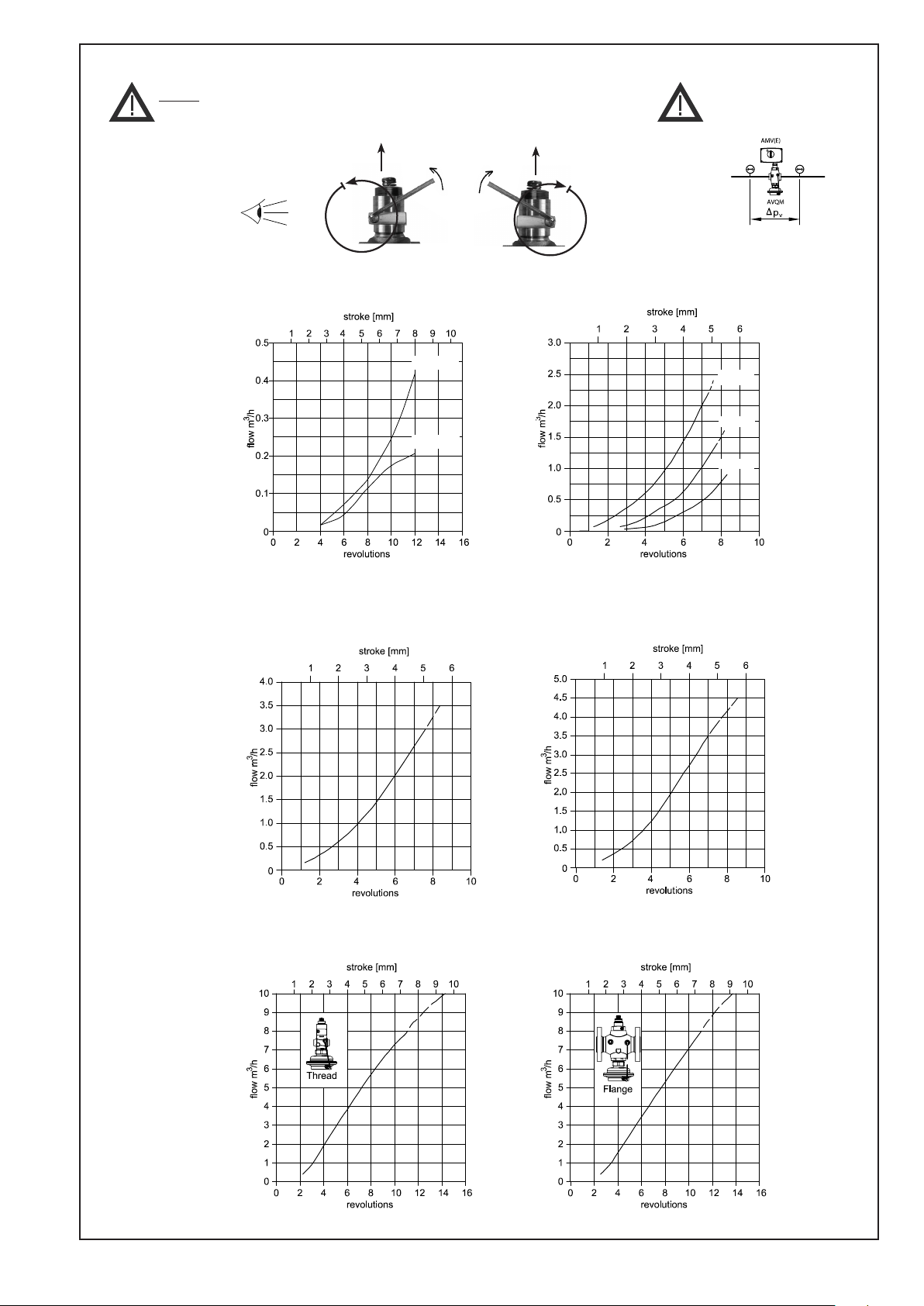
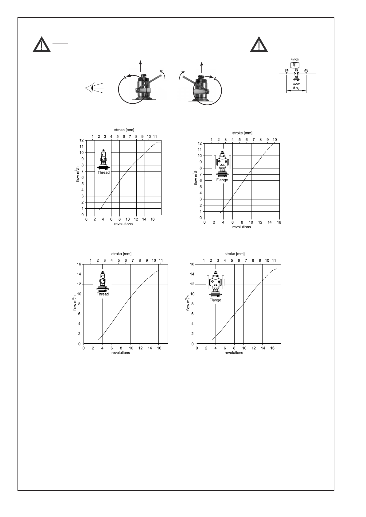
Flow Adjusting Curves PN 16 ⓯
Flow Rate Setting ⓫
The flow rate is adjusted by means of
limitation of control valve stroke ①②.
There are two possibilities:
1. Adjustment with the flow adjusting
curves,
2. Adjustment with heat meter.
Pre-condition ⓬
(min. diff. pressure over the valve)
To achieve maximum flow rate the pressure
difference Δpv ① across the control valve
must be at least: Δp
= 0.5 bar
min
Adjustment with flow adjusting
curves ⓭
The system don’t need to be active for
being adjusted.
1. Close control valve ① by turning the
adjustable flow restrictor ③④ to its
stop:
- at PN 16 controller to the right
(clockwise) ⑤
- at PN 25 controller to the right
(clockwise) ⑥ or to the left (counter
clockwise) ⑦
2. Select flow adjusting curve in the
diagram (see ⓯⓰).
Necessary
flow rate
Revolutions of
adjusting throttle
For PN 16 controller: 1 = 120°
For PN 25 controller: 1 = 360°
3. Open control valve ② with the
adjustable flow restrictor ⑧⑨ by
determined number of revolutions:
• at PN 16 controller to the left (counter
clockwise) ⑩
• at PN 25 controller to the left (counter
clockwise) ⑪ or to the right
(clockwise) ⑫
4. The setting of the valve stroke is
completed, continue with step 2,
Adjustment with Heat Meter.
Flow Adjusting Curves PN 25 ⓰
Adjustment with Heat Meter
Pre-condition:
The setting should be carried out when the
electrical actuator AMV(E) is dismounted. If
the electrical actuator is mounted, the stem
of the actuator must be retracted.
The system must be in operation. All units
in the system ❿ or a bypass must be
completely open.
1. Observe heat meter indicator. ⓭
At PN 16 controller:
- turning to the left (counter clockwise)
② increases the flow rate
- turning to the right (clockwise) ⑤
decreases the flow rate
At PN 25 controller:
- turning to the left (counter
clockwise) ⑪ or to the right
(clockwise) ⑫ increases the flow rate
- turning to the right (clockwise) ⑥
or to the left (counter clockwise) ⑦
decreases the flow rate.
After the adjustment has been completed ⓮
:
2. If not yet done, install the actuator ①,
see section Mounting of electrical
actuator.
3. Shortly throttle the system and then
reopen it (e.g. by means of the electrical
actuator).
4. Verify flow rate.
The control valve setting is completed.
5. The adjustable flow restrictor ②③ may
be sealed.
Temperature setting
(relevant only at AVQMT controllers)
See instructions for temperature actuator
AVT or safety temperature monitor
(actuator) STM.
The setting may be verified with help of a
heat meter if the system is in operation,
see next section.
8 VI.DB .T3.3F © Dan foss 02/2011 73695050 DH -SMT/SI
DANSK
Sikkerhedsnoter
Disse instruktioner SKAL læses omhyggeligt
forud for montering og indkøring samt
respekteres for at undgå skader på personer
og udstyr. Nødvendigt monterings-, opstartog vedligeholdelsesarbejde må kun
udføres af faglært og autoriseret personale.
Forud for monterings- og
vedligeholdelsesarbejde på regulatoren
skal systemet være:
- trykløst,
- nedkølet,
- tømt og
- rengjort.
Systemproducentens eller -operatørens
instruktioner skal overholdes.
Anvendelse
Regulatoren anvendes sammen med
elektriske aktuatorer AMV(E) til flow- (og
temperatur)styring af vand og vandglycolblandinger til varme-, ernvarme- og
kølesystemer.
AVQM PN 16 kan evt. kombineres med de
elektriske aktuatorer AMV(E) 10/13 (kun DN
15), AMV(E) 20/23, AMV 20/23 SL, AMV(E)
30/33, AMV 30 og AMV 150.
AVQM(T) PN 25 kan evt. kombineres med
de elektriske aktuatorer AMV(E) 10/13 (kun
DN 15), AMV(E) 20/23, AMV 20/23 SL,
AMV(E) 30/33, AMV 30 og AMV 150.
AVQMT PN 25 kan evt. kombineres med
temperaturaktuator AVT eller
sikkerhedstemperaturovervågning
(aktuator) STM.
De tekniske parametre på
produktetiketterne fastlægger
anvendelsen.
Montering
Tilladelige temperaturer ❶
Tilladelige positioner ❷
Medietemperaturer op til 100 °C:
- Kan installeres i alle positioner bortset
fra elektriske aktuatorer, der hænger
nedad
.
Medietemperaturer > 100 °C:
- Må kun installeres i vandrette
rørledninger med den elektriske
aktuator vendende opad.
Indbygning
AVQM(T) montering i returledning ❸
AVQM(T) montering i flowledning ❹
Ventilinstallation ❺
1. Rengør rørledningssystemet før
montering.
2. Det anbefales stærkt at installere et filter
foran regulatoren ①.
3. Installer ventilen
• Den flowretning, der vises på
produktetiketten eller på ventilen, skal
respekteres ② ③.
• Ventilen med monterede svejsestudser
må kun klemmes fast til
rørledningen ④.
TSvejsestudserne må kun svejses uden
ventil og pakninger! ⑤⑥
Høje svejsetemperaturer kan
ødelægge pakningerne, hvis disse
instruktioner ikke overholdes.
• Flanger ⑦ i rørledningen skal være
placeret parallelt, og pakfladerne skal
være rene og uden skader.
Krydsspænd skruerne i flangerne i 3
trin til maks. moment (50 Nm).
4. Forsigtig:
Rørledningerne må ikke belaste
ventilhuset mekanisk ⑧.
Montering af elektrisk aktuator ❻
Anbring den elektriske aktuator AMV(E) på
ventilen og spænd omløbermøtrikken med
nøgle SW 32.
Moment 25 Nm.
Andre detaljer:
Se instruktioner for elektrisk
aktuator AMV(E).
Montering af temperaturaktuator ❼
(kun relevant ved AVQMT-regulatorer)
Anbring temperaturaktuatoren AVT eller
STM ved membranen, og spænd
omløbermøtrikken med nøgle SW 50.
Moment 35 Nm.
Andre detaljer:
Se instruktioner for temperaturaktuator
AVT eller STM.
Mål, vægt ❾
1)
Konisk udv. gevind iht. EN 10226-1
2)
langer PN 25 iht. EN 1092-2
3)
Øvrige flangedimensioner – se tabel T1
for nipler.
* Ventilvægt (Valve weight)
** gevind (thread)
Opstart ❿
Påfyldning af systemet, første
opstart
1. Åbn ventilerne i systemet.
2. Åbn langsomt for afspærringsventilerne ① i flowledningen.
3. Åbn langsomt for afspærringsventilerne ② i returledningen.
Lækage- og trykprøvning
Afprøv ikke lukkede manøvreventiler med
tryk over 16 bar. Det kan beskadige
ventilen.
Trykprøvninger bør udføres før
monteringen af den elektriske aktuator.
Dette sikrer, at ventilen åbnes.
Før trykprøvning åbnes den justerbare
flowbegrænser ④ ⑤ ved at dreje den:
- i PN 16-regulatoren til venstre (mod
uret) ⑥
- i PN 25-regulatoren til venstre (mod
uret) ⑦ eller til højre (med uret) 8
Trykket skal øges gradvist ved (+/-)
tilslutningen ③.
Respekteres dette ikke, kan der opstå
skader på aktuator eller ventil. Der skal
udføres en trykprøvning af hele systemet i
overensstemmelse med producentens
instruktioner. Det maksimale prøvetryk er:
1,5 × PN
PN fremgår af produktetiketten!
Stop af anlæg
1. Luk langsomt for
afspærringsanordningerne ① i
flowledningen.
2. Luk langsomt for
afspærringsanordningerne ② i
returledningen.
Isolering ❽
Ved medietemperaturer op til 100 °C kan
Andre detaljer:
Se instruktioner til elektrisk aktuator
AMV(E). I tilfælde af AVQMT-regulator se
også instruktioner til temperaturaktuator
AVT eller sikkerhedstemperaturovervågning
(aktuator) STM.
73695050 DH -SMT/SI VI.DB .T3.3F © Dan foss 02/2011 9
trykaktuatoren ① også være isoleret.
Isolering af elektrisk aktuator ②
AMV(E) er ikke tilladt.
 Loading...