

Page 1
Operating Guide
AVQM, AVQMT – PN16 (DN 15-32) / PN25 (DN 15-50)
AVQM (PN 16)
DN 15-32
∆p = 0.2
ENGLISH
DANSK
DEUTSCH
ESPAÑOL
AVQM (PN 25)
DN 15-50
∆p = 0.2
Pressure independent control valve with integrated flow limiter AVQM, AVQMT www.danfoss.com Page 8
Trykuafhængig reguleringsventil med integreret flowbegrænser AVQM, AVQMT varme.danfoss.dk Side 9
Druckunabhängiges Regelventil mit integriertem Durchflussbegrenzer AVQM,
AVQMT
Válvulas de control independientes de la presión con limitador de caudal integrado
AVQM y AVQMT
DN 32-50
∆p = 0.2
AVQMT (PN 25)
DN 15-50
∆p = 0.2
DN 32-50
∆p = 0.2
AVQMT/AVT (PN 25)
DN 15-50
∆p = 0.2
www.danfoss.com Seite 10
www.danfoss.com Página 12
DN 32-50
∆p = 0.2
SLOVENŠČINA
POLSKI
MAGYAR
SRPSKI
ITALIANO
中文
Tlačno neodvisni regulacijski ventil z vgrajenim omejevalnikom pretoka AVQM, AVQMT
Niezależny od ciśnienia zawór regulacyjny z wbudowanym ogranicznikiem
przepł ywu AVQM, AVQMT
Nyomásfüggetlen szabályozó szelep beépített térfogatáram-korlátozóval AVQM,
AVQMT
Regulacioni ventil nezavisan od promene pritiska u sistemu sa ugrađenim limiterom
protoka AVQM, AVQMT
Valvola di regolazione indipendente dalla pressione con regolatore della portata
integrato AVQM, AVQMT
内置压差控制器的的压力无关型流量控制阀 AVQ M,AVQMT www.danfoss.com 第 20 页
www.danfoss.com Stran 13
www.heating.danfoss.pl
www.danfoss.com 16. oldal
www.danfoss.com Stranica 17
www.danfoss.com Pagina 18
Strona 14
© Danfoss | 2020.03
VI.LI.F3.3F | 1
Page 2
AVQM, AVQMT – PN16 (DN 15-32) / PN25 (DN 15-50)
❶
❸
MAINTENANCE
FREE
❷
AMV(E)
< 130 °C < 150 °C
②
①
③
< 100
°
C
❹
①
⑥
2 | © Danfoss | 2020.03
②
⑦
③
⑧
④
⑤
DN
15 69
20 74
25 79
32 104
L
(mm)
VI.LI.F3.3F
Page 3
AVQM, AVQMT – PN16 (DN 15-32) / PN25 (DN 15-50)
❺
❼
❽
< 100 °C
①
25 Nm max
> 100 oC
❻
35 Nm max
②
➒
①
②
③
–
+
❿
W41
① ② ③
⓫
②①
VI.LI.F3.3F
© Danfoss | 2020.03 | 3
Page 4
AVQM, AVQMT – PN16 (DN 15-32) / PN25 (DN 15-50)
⓬
PN 16
1 = 360°
360° = 1mm
DN 15
kvs 1.0
kvs 0.4
DN 20, kvs 6.3 DN 25, kvs 8.0
kvs 4.0
kvs 2.5
kvs 1.6
DN 32, kvs 10
4 | © Danfoss | 2020.03
VI.LI.F3.3F
Page 5
AVQM, AVQMT – PN16 (DN 15-32) / PN25 (DN 15-50)
⓭
PN 25
1 = 360°
360° = 1mm
DN 15
kvs 1.0
kvs 0.4
DN 20, k
DN 32, kvs 12. 5 DN 40, kvs 16
6.3 DN 25, kvs 8.0
vs
kvs 4.0
kvs 2.5
kvs 1.6
DN 50, kvs 20
VI.LI.F3.3F
DN 32, kvs 12. 5 DN 40, kvs 20
DN 50, kvs 25
© Danfoss | 2020.03 | 5
Page 6
AVQM, AVQMT – PN16 (DN 15-32) / PN25 (DN 15-50)
⓮
AVQM PN 16, PN 25
L3
d
sw
AVQM PN 16
DN 15 20 25 32
L
H 97 97 97 97
AMV(E) 10 276 – – –
AM V(E) 13 279 – – –
H*
AMV(E) 2./3. 289 289 292 293
AM V 150 278 – – –
H2 72 72 75 76
mm
L2
R
sw
65 70 75 100
T1
DN 15 20 25 32 40 50
SW
d 21 26 33 42 47 60
L1
sw
d2
n
45°
L
H2H
AVQM PN 16
DN 15-32
R ½ ¾ 1 1 ¼ 1 ½ 2
1)
L1
2)
L2
L3 139 154 159 184 204 234
k 65 75 85 100 110 12 5
k
d
2
n 4 4 4 4 4 4
1) Conical ext. th read acc. to EN 10226-1
2) Flanges PN 25, acc. t o EN 1092-2
121
AMV(E) 10 +
AVQM (DN 15)
32
(G ¾A)
130 150 160 - - -
mm
120 131 145 182 200 244
14 14 14 18 18 18
H*
AMV(E) 13 +
AVQM (DN 15)
121
41
(G 1A )
50
(G 1¼A)
H*
AMV(E) 2./ 3. +
AVQM (DN 15-32)
(G 1¾A)
155
63
70
(G 2A)
H*
82
(G 2½A)
92
AMV 150 +
AVQM (DN 15)
H*
AVQM/AVQMT PN 25
DN
L
L1 - - - 180 200 230
H 109 109 109 15 0 150 15 0
AMV(E) 10 291 - - - - AM V(E) 13 288 - - - - -
H*
AMV(E) 2./3. thread 301 301 304 371 371 371
AMV(E) 2./3. flange - - - 386 386 386
AM V 150 289 - - - - H1 - - - 150 15 0 150
H2 72 72 75 101 101 101
H3 - - - 101 101 101
H4 131 131 131 172 172 172
H5 - - - 17 2 172 172
3) Other fla nge dimensions – se e table for tailpiece s.
121
H*
15 20 25 32 40 50
65 70 75 100 110 130
mm
121
H*
155
Ø125
AVQM PN 25
DN 15-50
H*
L1
H3
H1
155
L
Ø125
AVQMT PN 25
DN 15-50
H2
H4
H3
H5
Ø125
AVQMT PN 25
DN 32-50
H*
L1
L
H2
H
Ø125
AVQM PN 25
DN 32-50
92
H*
AMV(E) 10 +
AVQM (DN 15)
6 | © Danfoss | 2020.03
AMV(E) 13 +
AVQM (DN 15)
AMV(E) 2./3. +
AVQM (DN 15-50)
AMV 150 +
AVQM (DN 15)
AMV(E) 2./3. +
AVQM (DN 32-50)
VI.LI.F3.3F
Page 7
AVQM, AVQMT – PN16 (DN 15-32) / PN25 (DN 15-50)
1
H
H
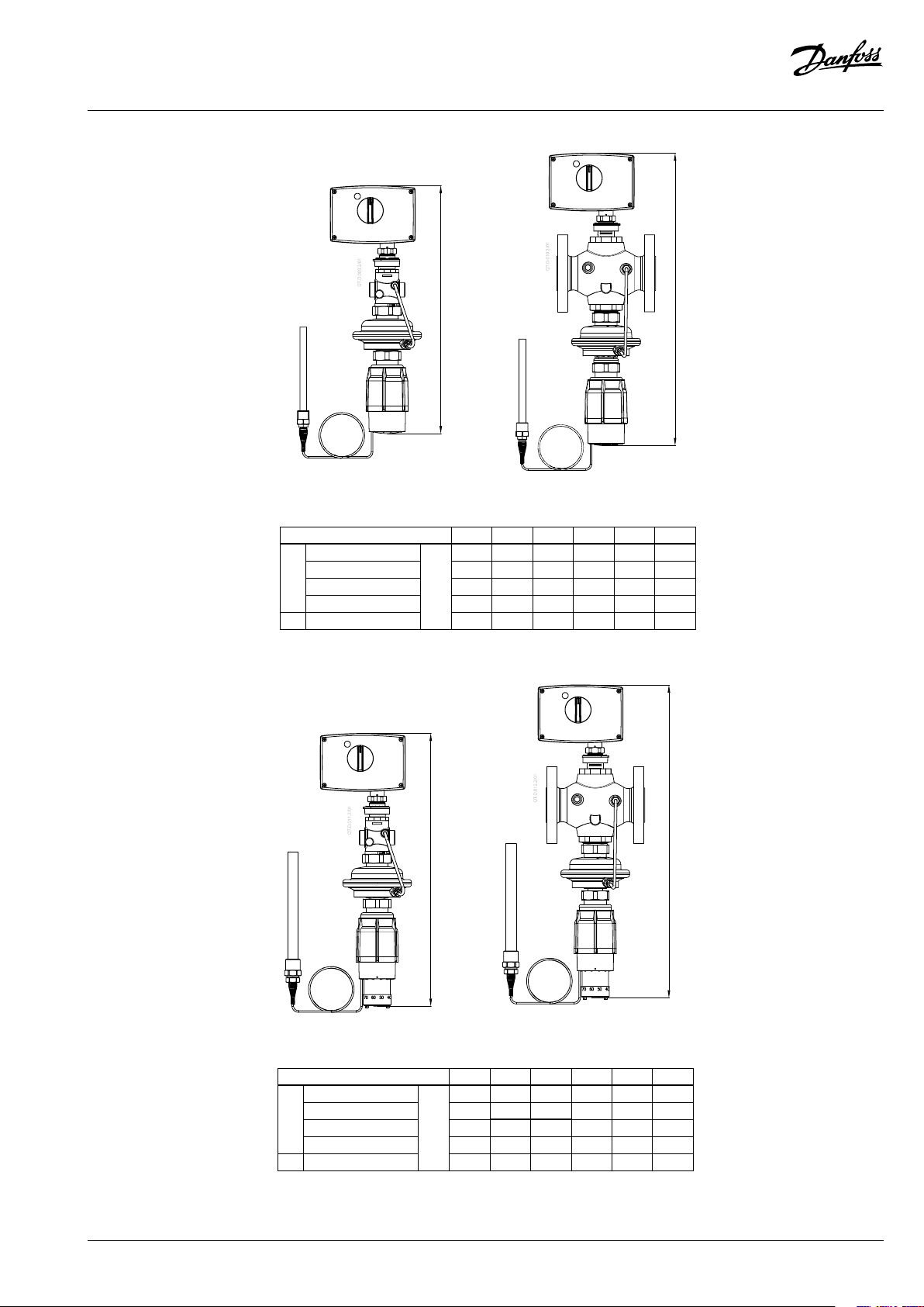
AVT / AVQMT / AMV(E) +
AVQM (DN 15-50)
AVT / AVQMT / AMV(E) +
AVQM (DN 32-50)
DN 15 20 25 32 40 50
AMV(E) 10
AM V(E) 13 341 - - - - -
H
AMV(E) 2./3. 451 451 454 521 521 521
338 - - - - -
mm
AM V 150 339 - - - - -
H
AMV(E) 2./3. - - - 521 521 521
1
1
H
H
VI.LI.F3.3F
STM / AVQMT / AMV(E) +
AVQM (DN 15-50)
STM / AVQMT / AMV(E) +
AVQM (DN 32-50)
DN 15 20 25 32 40 50
AMV(E) 10
AM V(E) 13 485 - - - - -
H
AMV(E) 2./3. 495 495 498 565 565 565
482 - - - - -
mm
AM V 150 483 - - - - -
H
AMV(E) 2./3. - - - 565 565 565
1
© Danfoss | 2020.03 | 7
Page 8

AVQM, AVQMT – PN16 (DN 15-32) / PN25 (DN 15-50)
See instructions for temperature
No
ENGLISH
Safety Notes
Prior to assembl y and commissioning to
avoid injury of persons and damages of
the devices, it is absolutely necessary
carefully read and observe these instructions.
Necessary assembly, start-up, and maintenance
work must be p erformed only by qual ified, trained
and authorized personnel.
Prior to assembly and maintenance work on the
controller, the system must be:
- depressurized,
- cooled down,
- emptied and
- cleaned.
Please comply with the instruc tions of the system
manufacturer or system operator.
Disposal
This product should be dismantled
and its components sorted, if
possible, in various groups before
recycling or disposal.
Always follow the local disposal regulations.
Definition of Application
The controller is in combination with electrical
actuators AMV(E) used for flow and temperature
control of water and water glycol mixtures for
heating, district heating and cooling systems.
AVQM PN 16 could be combined with electrical
actuator s AMV(E) 10/13 (DN15 only), AMV(E) 20/23,
AMV 20/23 SL, AMV(E) 30/33, AMV 30, AMV 150.
AVQM(T) PN 25 could be combined with electrical
actuator s AMV(E) 10/13 (DN15 only), AMV(E) 20/23,
AMV 20/23 SL, AMV(E) 30/33, AMV 30, AMV 150.
AVQMT PN 25 could be combined with
temperature actuator AVT or safety temperature
monitor (actuator) STM.
The technical parameters on the product labels
determine the use.
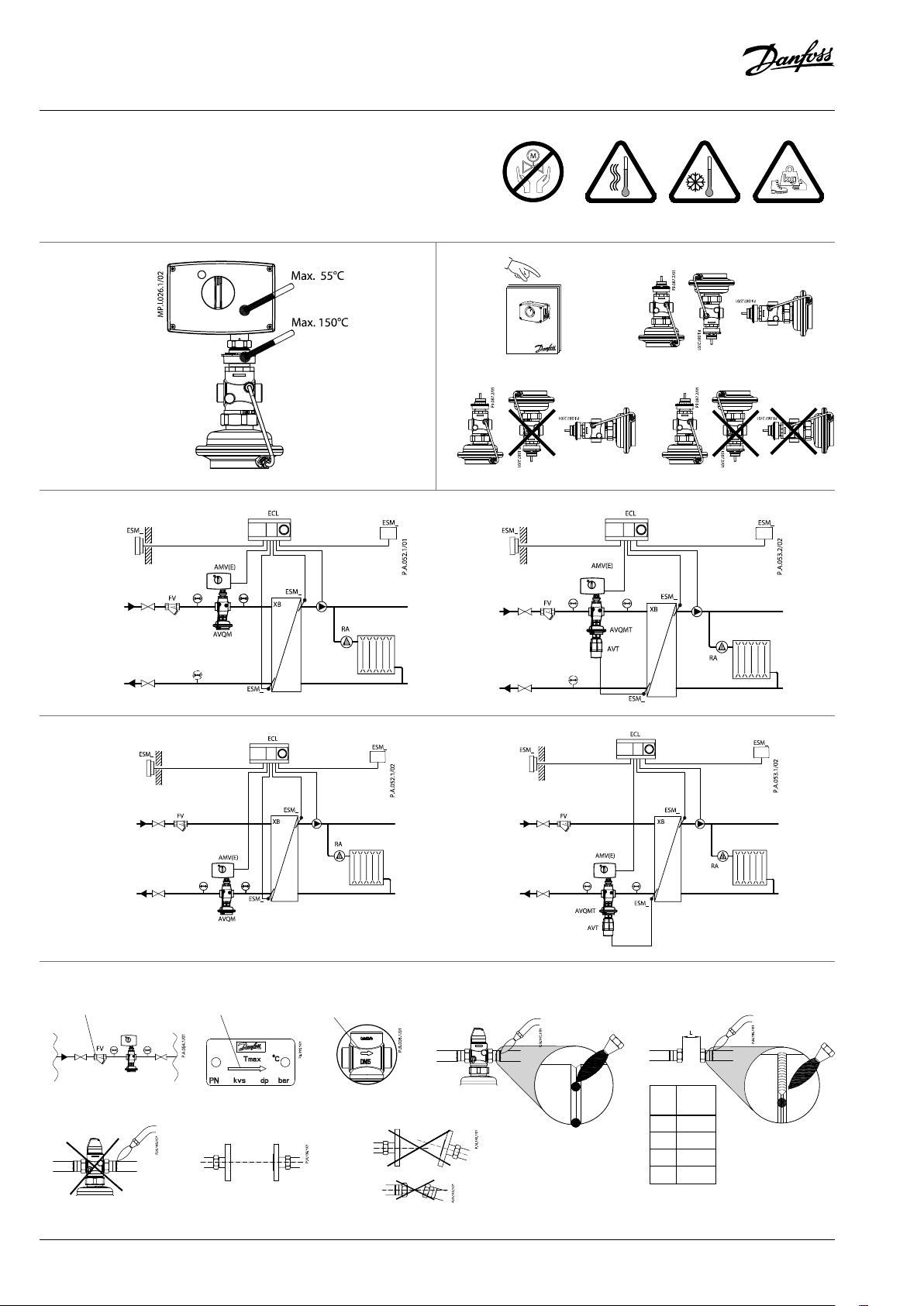
Installation Location and Installation
Scheme
AVQM(T) flow and return mounting ❸
to
Valve Installation ❹
1. Clean pipeline system prior to assembly.
2. The installation of a strainer ① in front of the
controller is strongly recommended.
3. Install valve
• The flow direction indicated on the
product label ② or on the valve ③ must be
observed.
• Spot weld to the pipeline ④.
Remove the valve and selas prior final
welding. ⑤⑥
If the valve and seals are not removed, high
welding temperatures may destroy them.
• Flanges ⑦ in the pipeline must be in
parallel position and sealing surfaces must
be clean and without any damage.
Tighten screws in flanges crosswise in 3
steps up to the maximum torque (50 Nm).
4. Caution:
Mechanical loads of the valve body by the
pipelines are not permitted ⑧.
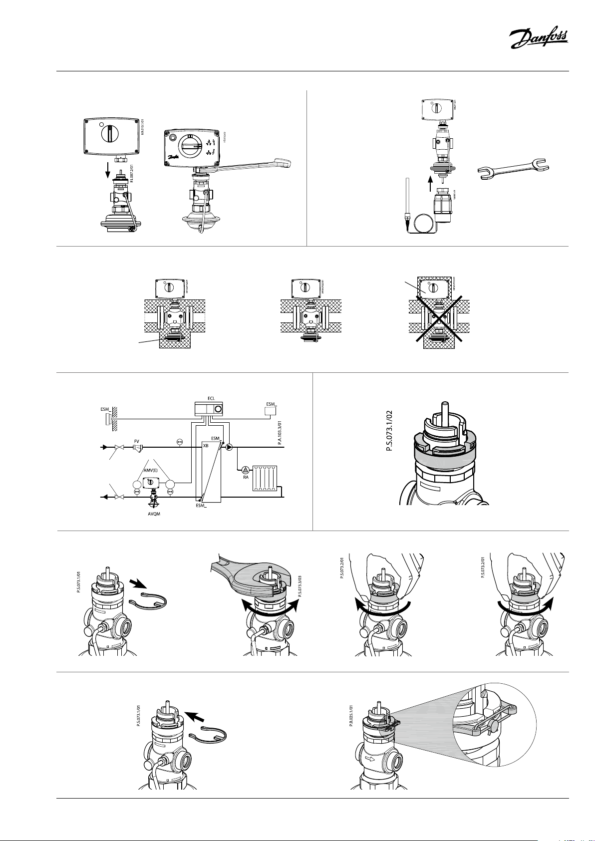
Mounting of electrical actuator ❺
Place electrical actuator AMV(E) on the valve and
tighten union nut with wrench SW 32.
Torque 25 Nm.
Other details:
See instructions for electrical actuator
AMV(E).
Mounting of temperature
actuator ❻
(relevant only at AVQMT controllers)
Place temperature actuator AVT or STM at the
diaphragm and tighten union nut with wrench
SW 50.
Torque 35 Nm.
Assembly
Admissible Temperatures ❶
Other details:
Admissible Installation Positions ❷
actuator AVT or STM .
① Media temperature <100°C:
Any position
② Media temperature 100°C to 130°C:
Horizontal and control valve up
③ Media temperature >130° to 150°C:
Control valve up
Other details:
See instructions for electrical actuator
AMV(E). In case of AVQMT controller
see instructions for temperature actuator AVT
or safety temperature monitor (actuator) STM
as well.
Insulation ❼
For media temp eratures up to 100 °C the pressure
actuator ① may also be insulated.
Insulation of electrical actuator ②
AMV(E) is not allowed.
Start-up ❽
Filling the system, first start-up
1. Open valves in the system.
2. Slowly open shut-off devices ① in the flow
pipeline.
3. Slowly open shut-off devices ② in the return
pipeline.
Leak and Pressure Tests
Do not test closed control valve with pressures
of more than 16 bar. Otherwise, the valve may
be damaged.
Pressure tests should be carried out prior to
the installation of the electrical actuator. This
guarantees that the valve is opened.
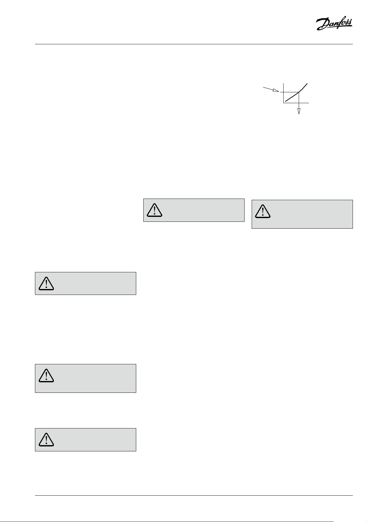
Before pressure test, open the adjustable flow
restrictor by turning it in counter clock direction:
Pressure must be gradually increased
at the (+/-) connection ③.
Non-compliance may cause damages at the
actuator or the valve.
A pressure test of th e entire system must be carr ied
out in accordance with manufacturer’s instructions.
The maximum test pressure is: 1.5 × PN
PN – see product label!
Putting out of operation
1. Slowly close shut-off devices ① in the flow
pipeline.
2. Slowly close shut-off devices ② in the return
pipeline.
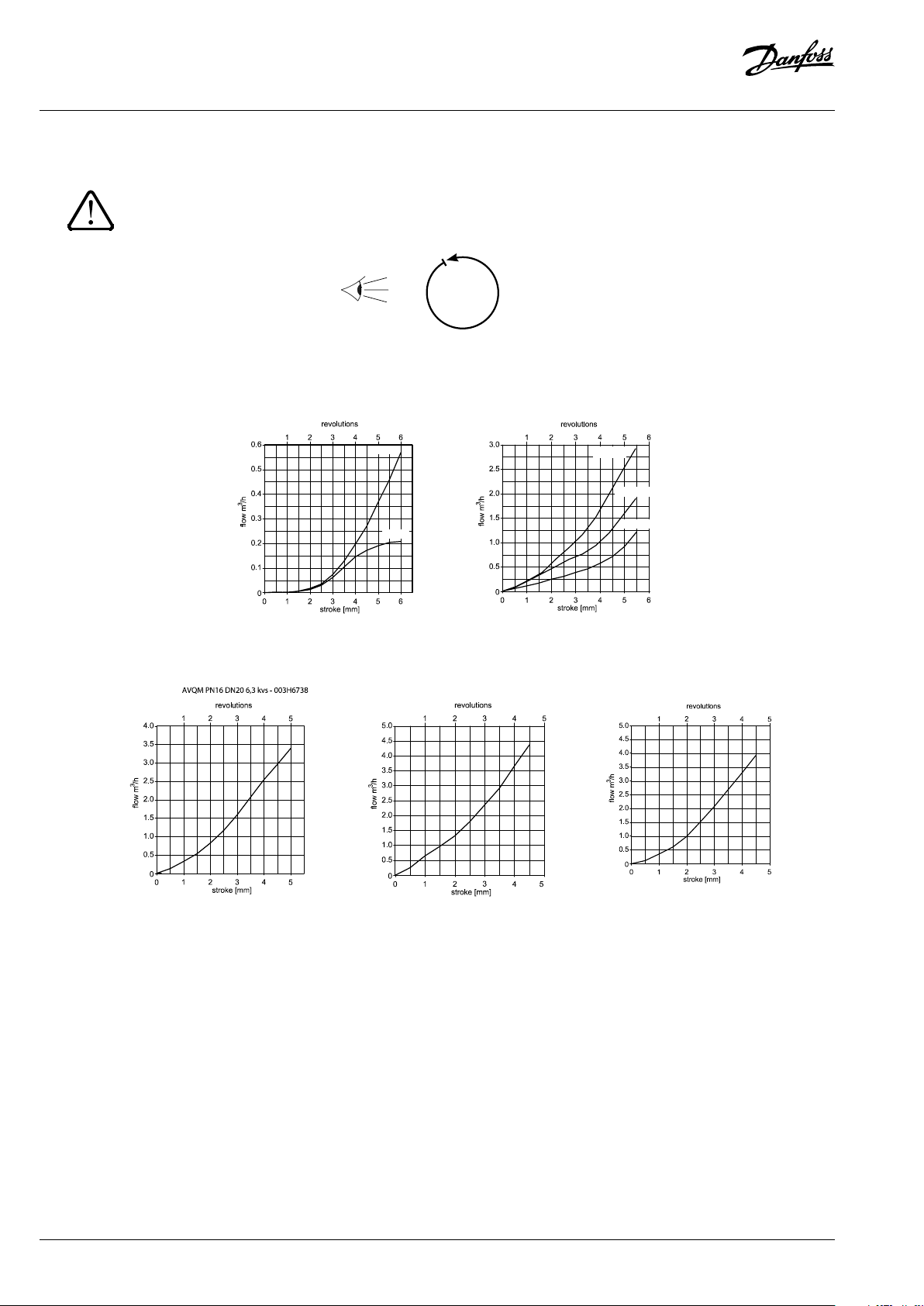
Max flow limiting ❾
The flow r ate is adjusted by means of limitation of
control valve stroke .
There are two possibilities:
1. Adjustment with the flow adjusting curves,
2. Adjustment with heat meter.
Pre-condition
The setting should be carried out when the
electrical actuator AMV(E) is dismounted.
If the electrical actuator is mounted, the stem of the
actuator must be retracted.
Adjustment with flow adjusting
curves ❿
The system don’t need to be active for being
adjusted.
1. Remove sealing ring ①
2. Close control valve ② by turning the
adjustable flow restrictor clockwise to its
stop.
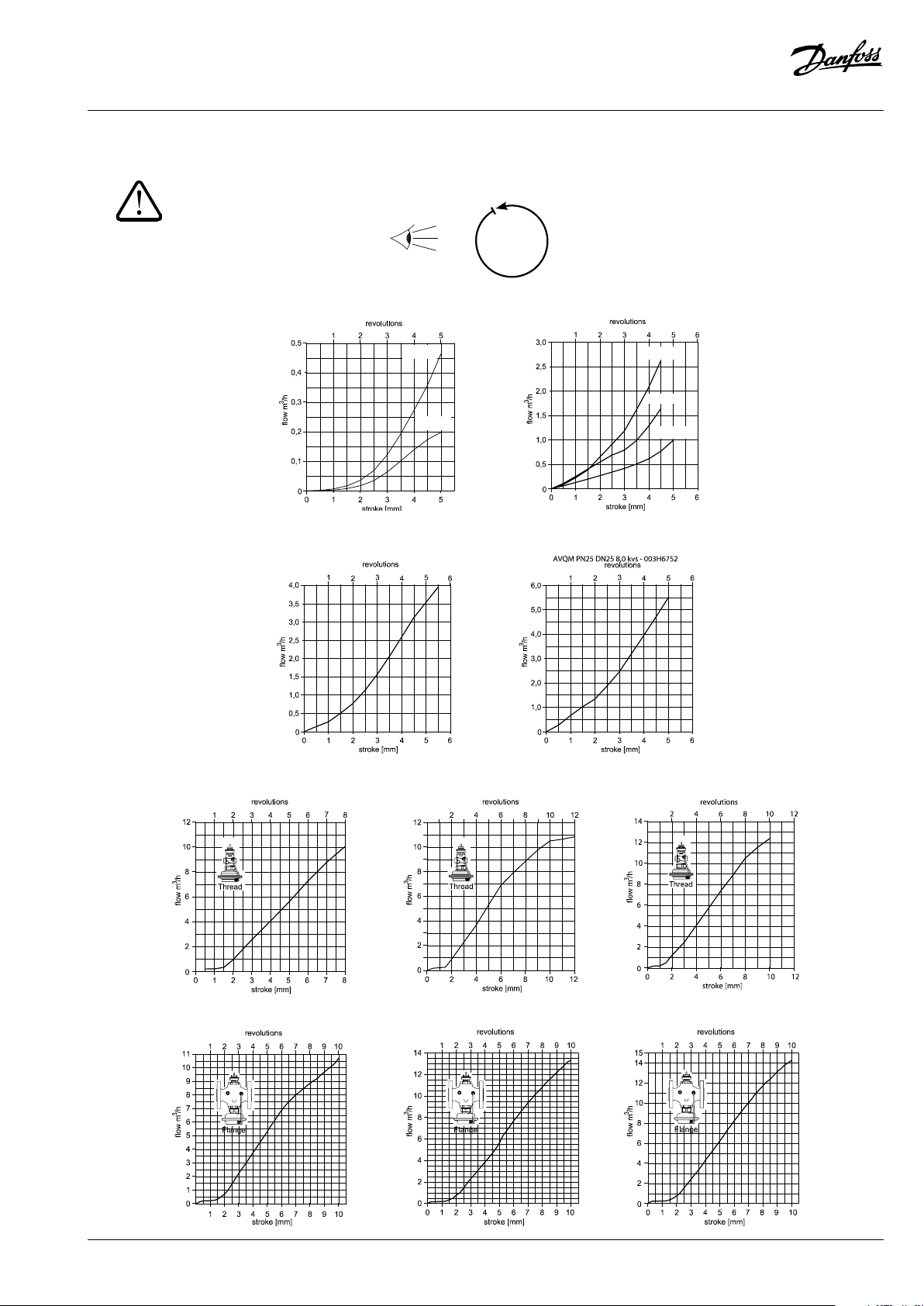
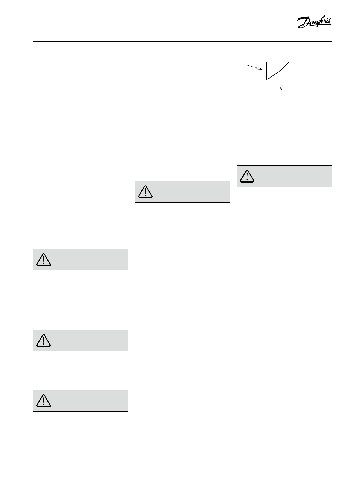
3. Select flow adjusting curve in the diagram
(see ⓬ for PN 16)
(see ⓭ for PN 25)
Necessary
flow rate
Revolutions of
adjusting throttle
3. Open control valve with the adjustable
flow restrictor by determined number of
revolutions counter clockwise ③.
8 | © Danfoss | 2020.03
VI.LI.F3.3F
Page 9

AVQM, AVQMT – PN16 (DN 15-32) / PN25 (DN 15-50)
til temperaturaktuatoren AVT eller
DANSK
4. Indication of setting can be seen by
comparing lower end of flow restriction nut
to marks on housing.
5. The setting of the valve stroke is completed,
continue with step 2, Adjustment with Heat
Meter.
The set ting may be verifie d with help of
a heat meter if the system is in
operation, see ne xt section.
Flow Adjusting Curves PN 16 ⓬
Flow Adjusting Curves PN 25 ⓭
Adjustment with Heat Meter
must be in operation. All units in the system ❽
must be completely open.
- turning counter clockwise ❿③ increases
the flow rate
- turning clockwise ❿③ decreases the flow
rate
After the adjustment has been completed
1. If not yet done, install the actuator ❺①
setting is completed.
2. After assambling sealing ring to the
adjustable flow restrictor ⓫① setting may
be sealed⓫②.
The system
:
Temperature setting
(relevant only at AVQMT controllers)
See instructions for temperature actuator AVT or
safety temperature monitor (actuator) STM.
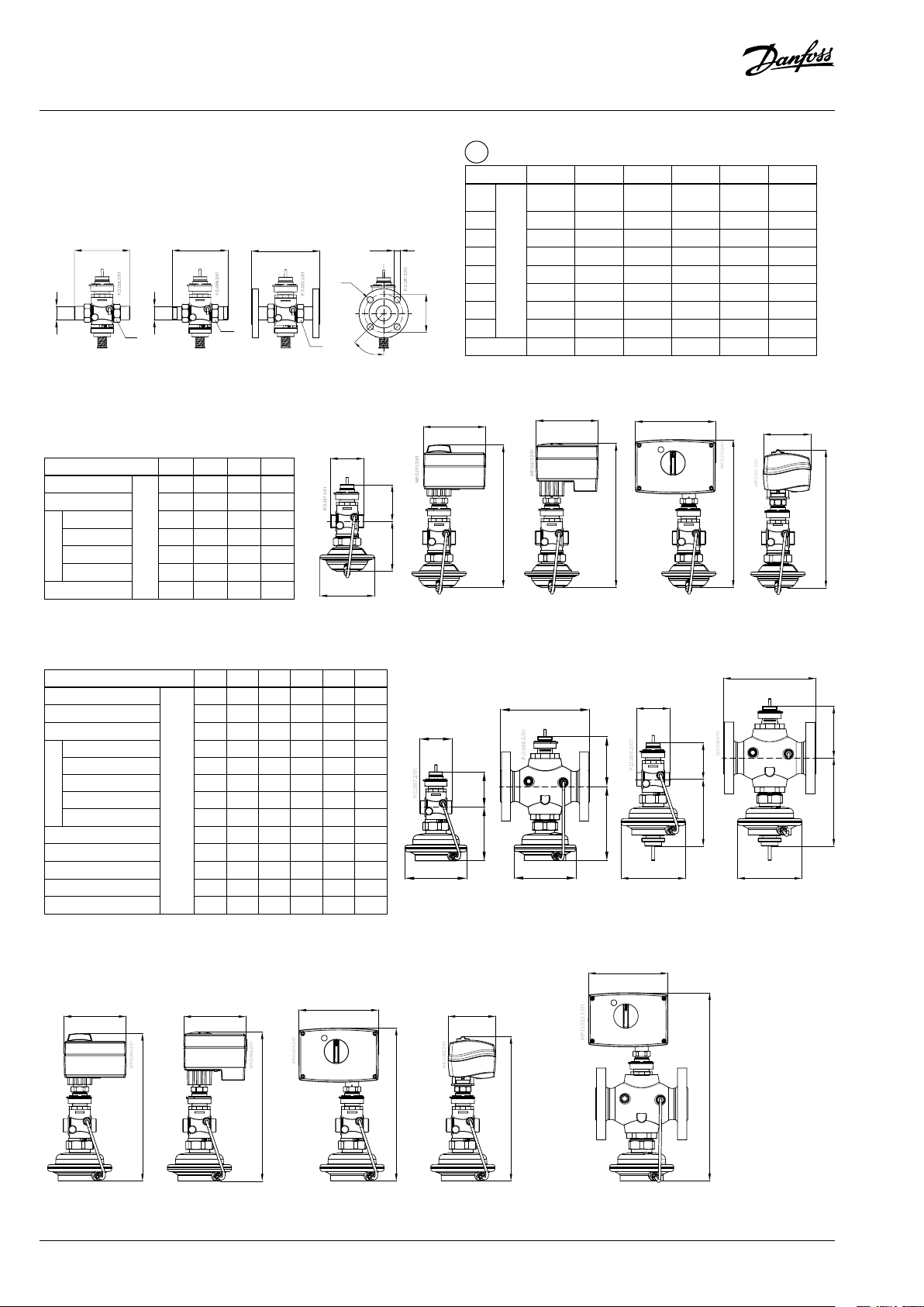
Dimensions, Weights ⓮
Sikkerhedsoplysninger
Disse instruktioner skal læses omhyggeligt
forud for montering og idriftsætning
samt overholdes for at undgå skader på
personer og udstyr.
Nødvendigt monterings-, opstarts- og
vedligeholdelsesarbejde må kun udføres af faglært
og autoriseret personale.
Forud for monterings- og vedligeholdelsesarbejde
på regulatoren skal systemet være:
- trykløst
- nedkølet
- tømt
- rengjort
Følg fabrikantens eller operatørens instruktioner.
Bortskaffelse
Før genbrug eller bortskaffelse
skal dette produkt skilles ad, og
enkeltdelene skal sorteres i
forskellige materialegrupper.
Der henvises til de lokale bestemmelser for
bortskaf felse.
Anvendelse
Regulatoren anvendes sammen med elektriske
motorer AMV(E) til f low- og temperaturreg ulering
af vand og blandinger med glykolvand til varme-,
fjernvarme- og køleanlæg.
AVQM PN 16 kan kombineres med de elektriske
motorer AMV(E) 10/13 (kun DN15), AMV(E) 20/23,
AMV 20/23 SL, AMV(E) 3 0/33, AMV 30 og AMV 150.
AVQM(T) PN 25 kan kombineres med de elektriske
motorer AMV(E) 10/13 (kun DN15), AMV(E) 20/23,
AMV 20/23 SL, AMV(E) 3 0/33, AMV 30 og AMV 150.
AVQMT PN 25 kan kombinere s med temperaturaktuatoren AVT eller sikkerhedstemperaturovervågningen (aktuatoren) STM.
De tekniske parametre på produktetiketterne
fastlægger anvendelsen.
Montering
Tilladelige temperaturer ❶
Monteringssteder og monteringsplan
Montering af AVQM(T) i fremløb- og returledning ❸
Ventilinstallation ❹
1. Rengør rørledningssystemet før montering.
2. Det anbefales kraftigt at installere et filter ①
foran regulatoren.
3. Installer ventilen
• Den flowretning, der vises på
produktetiketten ② eller på ventilen ③,
skal overholdes.
• Punktsvejs den fast på rørledningen ④.
Fjern ventilen og pakningerne før endelig
svejsning. ⑤⑥
Hvis ventilen og pakningerne ikke fjernes,
kan de blive ødelagt af de høje
temperaturer under svejsningen.
• Flangerne ⑦ i rørledningen skal være
placeret parallelt, og pakfladerne skal være
rene og uden skader.
Krydsspænd skruerne i flangerne i 3 trin til
maksimalt moment (50 Nm).
4. Forsigtig:
Rørledningerne må ikke belaste ventilhuset
mekanisk ⑧.
Montering af elektrisk aktuator ❺
Anbring den elektriske motor AMV(E) på ventile n,
og spænd omløbermøtrikken med nøgle NV 32.
Moment 25 Nm.
Andre detaljer:
Se instruktionerne til den elektriske
motor AMV(E).
Montering af temperaturaktuator ❻
(kun relevant ved AVQMT-regulatorer)
Anbring temp eraturaktuatoren AVT e ller STM ved
membranen, og spænd omløbermøtrikken med
nøgle NV 50.
Moment 35 Nm.
Andre detaljer:
Se instruktionerne til temperaturaktuatoren AVT eller S TM.
VI.LI.F3.3F
Tilladelige monteringspositioner ❷
① Medietemperatur på <100 °C: Hvilken som
helst position
② Medietemperatur på 100 °C til 130 °C:
Vandret og reguleringsventil opad
③ Medietemperatur på >130 °C til 150 °C:
Reguleringsventil opad
Andre detaljer:
Se instruktionerne til den elektriske
motor AMV(E). Ved brug af AVQMT-
regulator henvises der også til instruktionerne
sikkerhedstemperaturovervågningen SMT.
Isolering ❼
Ved medietemperaturer på op til 100 °C kan
trykaktuatoren ① også være isoleret.
Isolering af den elektriske aktuator ②
AMV(E) er ikke tilladt.
Opstart ❽
Påfyldning af systemet, første opstart
1. Åbn ventilerne i systemet.
2. Åbn langsomt for afspærringsanordningerne
① i flowledningen.
3. Åbn langsomt for afspærringsanordningerne
② i returledningen.
© Danfoss | 2020.03 | 9
Page 10

AVQM, AVQMT – PN16 (DN 15-32) / PN25 (DN 15-50)
No
Anleitungen für den elektrischen
Stellantrieb AMV(E) beachten.
Bei Verwendung eines Reglers AVQMT die
Lækage- og trykprøvning
Afprøv ikke luk kede reguleringsventil er med tryk
på over 16 bar. Det kan beskadige ventilen.
Trykprøvninger bør udføres før montering af den
elektriske motor. Dette sikrer, at ventilen åbnes.
Åbn den justerbare flowbegrænser før
trykprøvningen ved at dreje den mod uret.
Trykket skal øges gradvist ved (+/-)
tilslutningen ③.
Respekteres dette ikke, kan der opstå skader på
aktuatoren eller ventilen.
Der skal udf øres en trykprøvnin g af hele systemet
i overensstemmelse med producentens
instruktioner.
Det maksimale prøvetryk er: 1.5 × PN
PN – fremgår af produktetiketten!
Stop af anlæg
1. Luk langsomt for afspærringsanordningerne
① i fremløbet.
2. Luk langsomt for afspærringsanordningerne
② i returløbet.
Maks. flowbegrænsning ❾
Flowet justeres ved at begrænse reguleringsventilens vandring .
Der er to muligheder:
1. Justering vha. flowkurverne
2. Justering vha. varmemåler
Forudsætning
Indstillingen bør udføres, når den elektriske motor
AMV(E) er demonteret.
Hvis den elektriske aktuator er monteret, skal
motorens spindel være oppe.
Justering vha. flowkurver ❿
Systemet behøver ikke være aktivt for at blive
justeret.
1. Fjern tætningsringen ①
2. Luk reguleringsventilen ② ved at dreje den
justerbare flowbegrænser med uret, indtil
den stopper.
3. Vælg flowkurve i diagrammet
(se ⓬ for PN 16)
(se ⓭ for PN 25)
Nødvendigt
flow
Omdrejninger af
justeringsspjæld
3. Åbn reguleringsventilen ved at dreje den
justerbare flowbegrænser det fastlagte antal
omdrejninger mod uret ③.
4. Indstillingen kan ses ved at sammenligne den
nederste del af flowbegrænsermøtrikken
med mærkerne på huset.
5. Indstillingen af ventilvandringen er afsluttet,
fortsæt med trin 2, Justering vha. varmemåler.
Indstillingen kan verificeres vha. en
varmemåler, hvis systemet er i drift, se
næste afsnit.
Flowkurver PN 16 ⓬
* spindelvandring (stroke)
** flow (flow)
*** omdrejninger (revolutions)
**** gevind (Thread)
***** flange (Flange)
Flowkurver PN 25 ⓭
Justering vha. varmemåler
være i drift. Alle enheder i systemet ❽ skal være
helt åbne.
- Ved drejning mod uret ❿③ øges flowet.
- Ved drejning med uret ❿③ mindskes
flowet.
Efter endt justering
1. Hvis det ikke allerede gjort, skal aktuatoren
monteres ❺①, derefter er indstillingen
gennemført.
2. Efter montering af tætningsringen på den
justerbare flowbegrænser, ⓫① kan
fikseringen forsegles⓫②.
Indstilling af temperatur
(kun relevant ved AVQMT-regulatorer)
Se instruktionerne til temperaturaktuatoren AVT
eller sikkerhedstemperaturovervågningen
(aktuatoren) SMT.
Dimensioner, vægt ⓮
* 1) Konisk udv. gevind iht. EN 10226-1
(Conical ext. thread acc. to EN 10226-1)
** 2) Flanger PN 25 iht. EN 1092-2
(Flanges PN 25, acc. to EN 1092-2)
*** Vægt på ventil (Valve weight)
**** Vægt på ventil (gevind)
(Valve weight (thread))
***** Vægt på ventil (flange)
(Valve weight (flange))
****** 3) Andre flangedimensioner – se tabel
med nipler. (Other flange dimensions – see table
for tailpieces.)
DEUTSCH
Sicherheitshinweise
Um Verletzungen von Personen und
Schäden am Produkt zu vermeiden
diese Anleitung vor der Montage und
Inbetriebnahme unbedingt zu lesen und zu befolge n.
Erforderliche Montage-, Inbetriebnahme- und
Wartungsarbeiten dürfen nur von qualifizierten,
geschulten und autorisierten Fachkräften
durchgeführt werden.
Vor Montage- und Wartungsarbeiten am Regler
muss die Anlage:
- drucklos,
- abgekühlt,
- geleert und
- gesäubert sein.
Die Vorgaben des Anlagenherstellers und
Anlagenbetreibers sind zu beachten.
Systemet skal
:
Entsorgung
Vor der Entsorgung ist das Produkt
zu zerlegen. Die einzelnen
Komponenten sind nach
Werkstoffen getrennt zu entsorgen.
Die örtlichen Entsorgungsbestimmungen sind
zu beachten.
, ist
Bestimmungsgemäße Verwendung
Der Regler wird in Kombination mit dem
elektrischen Stellantrieb AMV(E) zur Durchflussund Temperaturreg elung von Wasser und WasserGlykol-Gemischen in Wärme-, Fernwärme- und
Kühlanlagen eingesetzt.
Das AVQM PN16 kann mit den elektrischen
Stellantrieben AMV(E) 10/13 (nur DN 15), AMV(E)
20/23, AMV 20/23 SL, AMV(E) 30/33, AMV 30 und
AMV 150 kombiniert werden.
Das AVQM(T) PN25 kann mit den elektrischen
Stellantrieben AMV(E) 10/13 (nur DN 15), AMV(E)
20/23, AMV 20/23 SL, AMV(E) 30/33, AMV 30 und
AMV 150 kombiniert werden.
Das AVQMT PN25 kann mit dem Temperaturregler
AVT oder mit dem Schutz-Temperatur-Wächter
(Stellantrieb) STM kombiniert werden.
Die technischen Daten auf den Typenschildern
sind für die Verwendung maßgebend.
Montage
Zulässige Temperaturen ❶
Zulässige Einbaulagen ❷
① Medientemperatur < 100 °C: Beliebige
Einbaulage
② Medientemperatur 100–130 °C: Horizontale
Einbaulage mit Regelventil oben
③ Medientemperatur > 130–150 °C: Einbaulage
mit Regelventil oben
Weitere Daten:
Anleitungen des Temperaturreglers AVT oder
des Schutz-Temperatur-Wächters (Stellantrieb)
STM beachten.
10 | © Danfoss | 2020.03
VI.LI.F3.3F
Page 11
AVQM, AVQMT – PN16 (DN 15-32) / PN25 (DN 15-50)
Anleitungen für den elektrischen
Siehe Anleitungen für den
Temperaturregler AVT oder den
Das Isolieren des elektrischen
ist nicht
No
genommener Anlage über einen
Einbauort und Einbauschema
Einbau des AVQM(T) im Vor- und Rücklauf ❸
Ventilmontage ❹
1. Vor der Montage das Rohrsystem reinigen.
2. Es wird nachdrücklich empfohlen, einen
Schmutzfänger① vor dem Regler einzubauen.
3. Ventil einbauen.
• Die auf dem Typenschild ② oder Ventil ③
angegebene Durchflussrichtung beachten.
• Durch Punktschweißen mit dem Rohr
verbinden ④.
Vor dem endgültigen Schweißen das Ventil
und die Dichtungen entfernen. ⑤⑥
Wenn das Ventil und die Dichtungen nicht
entfernt werden, können die Komponenten
durch hohe Schweißtemperaturen
beschädigt werden.
• Die Flansche ⑦ in der Rohrleitung müssen
parallel eingebaut werden. Die Dichtflächen
müssen sauber und unbeschädigt sein.
Die Schrauben der Flansche über Kreuz in drei
Schritten mit maximalem Drehmoment
(50 Nm) anziehen.
4. Vorsicht:
Mechanische Belastungen des Ventilgehäuses
durch die Rohrleitungen sind nicht zulässig ⑧.
Montage des elektrischen
Stellantriebs ❺
Den elektrischen Stellantrieb AMV(E) auf das Ventil
montieren und die Überwurfmutter mit einem
Schraubenschlüssel SW 32 anziehen.
Drehmoment: 25 Nm
Weitere Daten:
Stellantrieb AMV(E) beachten.
Montage des Temperaturreglers/
Schutz-Temperatur-Wächters ❻
(nur bei AVQMT-Reglern von Bedeutung)
Den Temperaturregler AVT oder den SchutzTemperatur-Wächter STM auf die Membran
montieren und die Überwurfmutter mit einem
Schraubenschlüssel SW 50 anziehen.
Drehmoment: 35 Nm
Weitere Daten:
Schutz-Temperatur-Wächter STM.
Wärmedämmung ❼
Bei Medie ntemperaturen bis 100 °C kann auch d er
Druckantrieb ① isoliert werden.
Stellantriebs AMV(E) ②
zulässig!
Inbetriebnahme ❽
Befüllung der Anlage, erste
Inbetriebnahme
1. Ventile in der Anlage öffnen.
2. Absperrarmaturen ① im Vorlauf langsam
öffnen.
3. Absperrarmaturen ② im Rücklauf langsam
öffnen.
Dichtheits- und Druckprüfung
Das geschlosse ne Regelventil darf nicht mi t einem
Druck von über 16 bar geprüft werden. Das Ventil
kann sonst beschädigt werden.
Druckprüfungen sollten vor dem Einbau des
elektrischen Stellantriebs durchgeführt werden.
Dadurch wird sichergestellt, dass das Ventil
geöffnet ist.
Den einstellbaren Durchflussbegrenzer vor
Druckprüfungen durch Drehen gegen den
Uhrzeigersinn öffnen:
Die Druckerhöhung muss am Anschluss
(+/-) gleichmäßig erfolgen③.
Bei Nichtbeachtung können der Antrieb oder das
Ventil beschädigt werden.
Eine für die ganze Anlage erforderliche
Druckprüfung ist gemäß den Vorgaben des
Anlagenherstellers vorzunehmen.
Max. Prüfdruck: 1.5 × PN
PN: Siehe Typenschild
Außerbetriebnahme
1. Absperrarmaturen ① im Vorlauf langsam
schließen.
2. Absperrarmaturen ② im Rücklauf langsam
schließen.
Maximale Durchflussbegrenzung ❾
Das Einstellen des Durchflusses erfolgt über die
Begrenzung des Regelventilhubs .
Es gibt zwei Möglichkeiten:
1. Einstellung mit Durchflusseinstelldiagramm
2. Einstellung mit Wärmemengenzähler
Voraussetzung
Die Einstellung sollte vorgenommen werden, wenn
der elektrische Stellantrieb AMV(E) noch nicht
montiert ist.
Wenn der elektrische Stellantrieb bereits eingebaut
ist, muss seine Antriebsstange komp lett eingefahren
werden.
Einstellung mit
Durchflusseinstelldiagrammen ❿
Die Anlage muss zu m Einstellen nicht in Betrieb s ein.
1. Dichtungsring entfernen ①.
2.
Regelventil ② schließen, indem der einstellbare
Durchflussbegrenzer bis zum Anschlag
gegen den Uhrzeigersinn gedreht wird.
3. Einstelldiagramm auswählen.
(Siehe ⓬ für PN 16.)
(Siehe ⓭ für PN 25.)
Erforderlicher
Durchfluss
Umdrehungen des einstellbaren
Durchflussbegrenzers
3. Regelventil öffnen, indem der einstellbare
Durchflussbegrenzer entsprechend der
erforderlichen Anzahl an Umdrehungen
gegen den Uhrzeigersinn gedreht wird ③.
4. Die Einstellung kann überprüft werden,
indem das untere Ende der Durchflussbegrenzungsmutter mit den Markierungen
auf dem Gehäuse verglichen wird.
5. Die Einstellung des Ventilhubs ist
abgeschlossen. Mit Schritt 2: Einstellung mit
Wärmemengenzähler fortfahren.
Die Einstellung kann bei in Betrieb
Wärmemengenzähler geprüft werden,
siehe nächsten Abschnitt.
Einstelldiagramme PN 16 ⓬
* Hub (stroke)
** Durchfluss (flow)
*** Umdrehungen (revolutions)
**** Gewinde (Thread)
***** Flansch (Flange)
Einstelldiagramme PN 25 ⓭
Einstellung mit Wärmemengenzähler
Die Anlage muss in Betrieb sein. Alle Armaturen
in der Anlage ❽ müssen vollständig geöffnet sein.
- Drehung gegen den Uhrzeigersinn ❿③
erhöht den Durchfluss.
- Drehung im Uhrzeigersinn ❿③ verringert
den Durchfluss.
Nach abgeschlossener Einstellung
1. Falls noch nicht geschehen, den Stellantrieb
❺① nach abgeschlossenem Einstellvorgang
montieren.
2. Nach der Montage des Dichtungsrings am
einstellbaren Durchflussbegrenzer ⓫①
kann die Einstellung verriegelt werden ⓫②.
:
Temperatureinstellung
(nur bei AVQMT-Reglern von Bedeutung)
Die Anleitungen des Temperaturreglers AVT oder
des Schutz-Temperatur-Wächters (Stellantrieb)
STM beachten.
Abmessungen, Gewichtsangaben ⓮
* 1) Kegeliges Außengewinde gemäß DIN EN
10226-1 (Conical ext. thread acc. to EN 10226-1)
** 2) Flansche PN 25 gemäß DIN EN 1092-2
(Flanges PN 25, acc. to EN 1092-2)
*** Ventilgewicht (Valve weight)
**** Ventilgewicht (Gewinde) (Valve weight (thread))
***** Ventilgewicht (Flansch) (Valve weight (flange))
****** 3) Weitere Flanschmaße – siehe die
Tabelle für Endstücke (Other flange dimensions
– see table for tailpieces.)
VI.LI.F3.3F
© Danfoss | 2020.03 | 11
Page 12

AVQM, AVQMT – PN16 (DN 15-32) / PN25 (DN 15-50)
AVQMT, consulte también las instrucciones
La presión debe incrementarse
No
ESPAÑOL
Notas de seguridad
A fin de evit ar lesiones personal es y daños
a los dispositivos, se considera
imprescindible leer detenidamente y
respetar estas instrucciones antes de montar el
componente y llevar a cabo su pu esta en servicio.
Las operaciones de montaje, puesta en marcha y
mantenimiento deb en ser realizadas únicamente
por personal cualificado, autorizado y con la
debida formación.
Antes de montar el controlador o llevar a cabo
labores de mantenimiento en relación con el
mismo, el sistema debe:
- despresurizarse;
- enfriarse;
- vaciarse; y
- lavarse.
Respete las instrucciones del fabricante u operador
del sistema.
Eliminación
Antes de desechar este producto,
desmóntelo y clasifique sus compo
nentes, si es posible, en diferentes gru-
pos para su reciclaje o eliminación.
Respete siempre las nor mas vigentes en materia
de eliminación.
Aplicaciones
En combinación con un actuador eléctrico AMV(E),
el controlador se emplea para controlar el caudal
y la temperatura del agua y las mezclas de agua/
glicol en sistemas de calefacción, calefacción y
refrigeración urbana.
El controlador AVQM PN 16 se puede combinar
con los actuadores eléctricos AMV(E) 10/13 (sólo
DN 15), AMV(E) 20/23, AMV 20/23 SL, AMV(E) 30/33,
AMV 30 y AMV 150.
El controlador AVQM(T) PN 25 se puede combinar
con los actuadores eléctricos AMV(E) 10/13 (sólo
DN 15), AMV(E) 20/23, AMV 20/23 SL, AMV(E) 30/33,
AMV 30 y AMV 150.
El controlador AVQMT PN 25 se puede combinar
con el actuador de temperatura AVT o el monitor
(actuador) de temperatura de seguridad STM.
El uso debe dete rminarse a partir de los p arámetros
técnicos especificados en las etiquetas del
producto.
Lugar y tipo de instalación
Montaje en impulsión y retorno del controlador
AVQM(T) ❸
Instalación de la válvula ❹
1. Limpie el sistema de tuberías antes de llevar
a cabo el montaje.
2. Se recomienda encarecidamente instalar un
filtro ① antes del controlador.
3. Instale la válvula:
• Debe respetarse el sentido de caudal
indicado en la etiqueta del producto ② o la
válvula ③.
• Suelde por puntos la válvula a la tubería ④.
Retire la válvula y los sellos antes de la
soldadura final. ⑤⑥
Si no retira la válvula y los sellos, las
elevadas temperaturas que se alcanzan
durante la soldadura final podrían causar
daños irreparables en los mismos.
• Las bridas ⑦ de las tuberías deben ser
paralelas; asimismo, las superficies de unión
deben estar limpias y no presentar daños.
Apriete los tornillos de las bridas en orden
-
cruzado; hágalo en 3 pasos hasta alcanzar
el par de apriete máximo (50 N·m).
4. Precaución:
El cuerpo de la válvula no admite cargas
mecánicas impuestas por las tuberías ⑧.
Montaje del actuador eléctrico ❺
Coloque el ac tuador eléctrico A MV(E) en la válvu la
y apriete la tuerca de unión con una llave SW 32.
Aplique un par de apriete de 25 N·m.
Otros datos:
Consulte las instrucciones del actuador
eléctrico AMV(E).
Montaje del actuador de
temperatura ❻
(sólo para controladores AVQMT)
Coloque el actuador de temperatura AVT o STM
en el diafragma y apriete la tuerca de unión con
una llave SW 50.
Aplique un par de apriete de 35 N·m.
Otros datos:
Consulte las instrucciones del actuador
de temperatura AVT o STM .
Montaje
Temperaturas admisibles ❶
Posiciones de instalación admisibles ❷
① Temperatura del medio < 100 °C: cualquier
posición
② Temperatura del medio entre 100 °C y 130 °C:
horizontal, con la válvula de control hacia arriba
③ Temperatura del medio entre 130 °C y 150 °C:
con la válvula de control hacia arriba
Otros datos:
Consulte las instrucciones del actuador
eléctrico AMV(E). Para controladores
del actuador de temperatura AVT o el monitor
(actuador) de temperatura de seguridad STM.
Aislamiento ❼
Para medios a temperaturas de hasta 100 °C,
también se puede aislar el actuador eléctrico ①.
El aislamiento del actuador eléctrico②
AMV(E) no está permitido.
Arranque ❽
Llenado del sistema y primer arranque
1. Abra las válvulas del sistema.
2. Lentamente, abra los dispositivos de corte ①
de la tubería de impulsión.
3. Lentamente, abra los dispositivos de corte ②
de la tubería de retorno.
Pruebas de fugas y presión
No pruebe la válvula de control cerrada empleando
presiones superiores a 16 bar. De lo contrario, la
válvula podría resultar dañada.
Las prueb as de presión deben llevar se a cabo antes
de instalar el actuador eléctrico. Ello garantizará
que la válvula se encuentre abierta.
Antes de la prueba de presión, abra el limitador
de caudal ajustable girándolo en sentido contrario
a las agujas del reloj.
gradualmente mediante la conexión
(+/-) ③.
No cumplir este r equisito puede dar lugar a dañ os
en el actuador o la válvula.
Debe llevarse a cabo una prueba de presión sobre
el sistema completo de acuerdo con las
instrucciones del fabricante.
La presión de prueba máxima es: 1.5 × PN.
PN: ¡consulte la etiqueta del producto!
Puesta fuera de servicio
1. Lentamente, cierre los dispositivos de
corte ① de la tubería de impulsión.
2. Lentamente, cierre los dispositivos de corte
② de la tubería de retorno.
Limitación del caudal máximo ❾
El caudal se ajust a limitando la carrera de la v álvula
de control.
Existen dos posibilidades:
1. Ajuste con las curvas de ajuste de caudal.
2. Ajuste con contador de calor.
Condiciones previas
El ajuste debe haberse llevado a cabo al desmontar
el actuador eléctrico AMV(E).
Al montar el actuador eléctrico, el vástago debe
encontrarse retraído.
Ajuste con curvas de ajuste de caudal ❿
No es necesario que el sistema esté en
funcionamiento para ajustarlo.
1. Retire el anillo de sellado ①.
2. Cierre la válvula de control ② girando el
limitador de caudal ajustable en el sentido
de las agujas del reloj hasta el tope.
3. Seleccione una curva de ajuste de caudal en
el diagrama:
(⓬ para PN 16)
(⓭ para PN 25)
Caudal necesario
Vueltas del mando
de ajuste
12 | © Danfoss | 2020.03
VI.LI.F3.3F
Page 13

AVQM, AVQMT – PN16 (DN 15-32) / PN25 (DN 15-50)
Glejte navodila za termostatske
SLOVENŠČINA
3. Abra la válvula de control girando el limitador
de caudal ajustable el número de vueltas
determinado en sentido contrario a las
agujas del reloj ③.
4. Puede obtenerse una indicación del ajuste
comparando el extremo inferior de la tuerca
de limitación de caudal con las marcas de
la carcasa.
5.
Aquí finaliza el ajuste del recorrido de la válvula.
Pase al paso 2: “Ajuste con contador de calor”.
El ajuste se puede verificar con ayuda
de un contador de calor si el sistema se
encuentra en funcionamiento (consulte
la siguiente sección).
Curvas de ajuste de caudal (PN 16) ⓬
* carrera (stroke)
** caudal (flow)
*** vueltas (revolutions)
**** Rosca (Thread)
***** Brida (Flange)
Curvas de ajuste de caudal (PN 25) ⓭
Ajuste con contador de calor
debe encontrarse en funcionamiento. Todas las
unidades del sistema ❽ deben encontrarse
completamente abiertas.
- Girar en sentido contrario a las agujas del
reloj ❿③ para aumentar el caudal.
- Girar en el sentido de las agujas del reloj
❿③ para reducir el caudal.
Una vez llevado a cabo el ajuste
1. Si no lo ha hecho ya, instale el actuador ❺①.
Aquí finaliza el ajuste.
2. Tras montar el anillo de sellado en el
limitador de caudal ajustable ⓫①, puede
bloquearse el ajuste⓫②.
El sistema
:
Ajuste de la temperatura
(sólo para controladores AVQMT)
Consulte las instrucciones del actuador de
temperatura AVT o el monitor (actuador) de
temperatura de seguridad STM.
Dimensiones y pesos ⓮
* 1) Rosca cónica ext. según norma EN 10226-1
(Conical ext. thread acc. to EN 10226-1)
** 2) Bridas PN 25 según norma EN 1092-2
(Flanges PN 25, acc. to EN 1092-2)
*** Peso de la válvula (Valve weight)
**** Peso de la válvula (rosca)
(Valve weight (thread))
***** Peso de la válvula (brida)
(Valve weight (flange))
****** 3) Bridas de otros tamaños (consulte la
tabla de racores) (Other flange dimensions – see
table for tailpieces.)
Varnostna opozorila
Izjemno pomembno je, da pred montažo
in zagonom skrbno preberete navodila
in jih upoštevate. S tem se izognete
poškodbam pri posamezniku in okv aram na opremi.
Potrebno montažo, zagon in vzdrževalna dela
lahko izvajajo samo kvalificirani, usposobljeni in
pooblaščeni delavci.
Pred montažo in vzdrževalnimi deli na regulatorju
morajo biti izpolnjeni naslednji pogoji:
– v sistemu ne sme biti nadtlaka,
– sistem mora biti ohlajen,
– izpraznjen in
– očiščen.
Prosimo, upoštevajte navodila proiz vajalca sistema
ali sistemskega operaterja.
Odstranjevanje
Pred reciklažo ali odstranitvijo je
potrebo pogon demontirati in dele
pogona raz vrstiti v ustrezne skupine .
Vedno upoštevajte veljavno lokalno
zakonodajo o odstranitvi.
Opis naprave
Regulator se up orablja skupaj z elek tričnimi pogoni
AMV(E) za regulacijo pretoka in temperature v
sistemih ogrevanja, daljinskega ogrevanja in hlajenja,
napolnjenih z vo do ali z mešanico vode in glikola.
AVQM PN 16 je mogoče kombinirati z električnimi
pogoni AMV(E) 10/13 (samo DN15), AMV(E) 20/23,
AMV 20/23 SL, AMV(E) 30/33, AMV 30, AMV 150.
AVQM(T) PN 25 je mogoče kombinirati z
električnimi pogoni AMV(E) 10/13 (samo DN15),
AMV(E) 20/23, AMV 20/23 SL, AMV(E) 30/33, AMV
30, AMV 150.
AVQMT PN 25 je mogoče kombinirati s termostatskim
pogonom AVT ali varnostnim nadzornikom
temperature (termostatom) STM.
Tehnični podatki na et iketi izdelka določa jo uporabo.
Montaža
Dopustne temperature ❶
Dopustni položaji vgradnje ❷
① Temperatura medija < 100 °C: Kateri koli položaj
② Temperatura medija 100 °C do 130 °C:
Horizontalni in regulacijski ventil gor
③ Temperatura medija > 130 °C do 150 °C:
Regulacijski ventil gor
Druge podrobnosti:
Glejte navodila za električni pogon
AMV(E). V primeru regulatorja AVQMT
glejte tudi navodil a za termostatski pogon AVT ali
varnostni nadzornik temperature (termostat) STM.
Mesto vgradnje in shema vgradnje
Vgradnja pretoka in povratka AVQM(T) ❸
Vgradnja ventila ❹
1. Pred montažo očistite cevovod.
2. Močno priporočamo vgradnjo filtra ①
pred regulator.
3. Vgradite ventil
• Upoštevajte puščico na etiketi proizvoda
② oz. na ventilu ③, ki kaže smer pretoka.
• Točkasto privarite na cevovod ④.
Pred končnim varjenjem odstranite ventil
in tesnila. ⑤⑥
Če ne odstranite ventila in tesnil, jih lahko
visoke temperature varjenja uničijo.
• Prirobnice ⑦ cevovoda morajo biti
vzporedne, tesnilne površine pa morajo
biti čiste in brez poškodb.
Pritegnite vijake na prirobnicah križem v treh
korakih do maksimalnega momenta (50 Nm).
4. Pozor:
Mehanske obremenit ve cevovoda na telo
ventila niso dovoljene ⑧.
Montaža električnega pogona ❺
Električni pogon AMV(E) namestite na ventil in
spojno matico privijte z viličastim ključem SW 32.
Moment 25 Nm.
Druge podrobnosti:
Glejte navodila za električni pogon
AMV(E).
Vgradnja termostatskega pogona ❻
(velja samo za regulatorje AVQMT)
Termostatski pogon AVT ali STM namestite na
membrano in privijte spojno matico z viličastim
ključem SW 50.
Moment 35 Nm.
Druge podrobnosti:
pogone AVT ali S TM.
Izolacija ❼
Pri temperaturah medija do 100 °C je mogoče
tlačni pogon ① tudi izolirati.
Izolacija električnega pogona ② AMV(E)
ni dovoljena.
Zagon ❽
Polnjenje sistema, prvi zagon
1. Odprite ventile v sistemu.
2. Počasi odprite zaporne organe ① v dovodu.
3. Počasi odprite zaporne organe ② v povratku.
VI.LI.F3.3F
© Danfoss | 2020.03 | 13
Page 14

AVQM, AVQMT – PN16 (DN 15-32) / PN25 (DN 15-50)
mora tlak
No
Patrz instrukcje dla siłowników
Test tesnosti in tlaka
Ne testirajte pri zaprtem regulacijskem ventilu
s tlakom nad 16 bar. V nasprotnem primeru lahko
poškodujete ventil.
Tlačne preizkuse je treba opraviti pred vgradnjo
elektr ičnega pogona. To zagotavlja , da je ventil odprt.
Pred tlačnim preizkusom odprite nastavljiv
omejevalnik p retoka tako, da ga zavr tite v nasprotni
smeri urinega kazalca:
4. Nastavitev lahko ugotovite tako, da primerjate
spodnji konec matice za omejitev pretoka
z oznakami na ohišju.
5.
Nastavitev hoda ventila je zaključena; nadaljujte
z 2. korakom: nastavitev z merilnikom toplote.
Nastavitev lahko preverimo s pomočjo
merilnika toplote, če sistem deluje;
glejte naslednje poglavje.
Krivulje za nastavitev pretoka PN 16 ⓬
Na (+/-) priključkih ③
naraščati postop oma.
Neskladnost z navodili lahko povzroči poškodbe
na pogonu ali na ventilu.
Tlačni preizk us celotnega sistema se mora i zvajati
po navodilih proizvajalca.
Maksimalni preizkusni tlak znaša: 1.5 × PN
PN – glejte napisno ploščico!
Jemanje iz obratovanja
1. Počasi zaprite zaporne organe ① v dovodu.
2. Počasi zaprite zaporne organe ② v povratku.
Omejitev maksimalnega pretoka ❾
Pretok prilagodimo z omejitvijo hoda
regulacijskega ventila .
Obstajata dve možnosti:
1. prilagoditev z nastavitvenimi krivuljami
pretoka,
2. prilagoditev z merilnikom toplote.
Predpogoj
Nastavitev je treba opraviti, ko je električni pogon
AMV(E) demontiran.
Če je električni pogon nameščen, mora biti drog
pogona uvlečen.
Prilagoditev z nastavitvenimi
krivuljami pretoka ❿
Za prilagoditev ni potrebno, da sistem deluje.
1. Odstranite tesnilni obroč ①
2. Zaprite regulacijski ventil ② tako, da
nastavljiv omejevalnik pretoka zavrtite v
smeri urinega kazalca, dokler se ne ustavi.
3. V diagramu izberite krivuljo za nastavitev
pretoka (glejte ⓬ za PN 16)
(glejte ⓭ za PN 25)
Potreben
pretok
Obrati nastavitvene
puše
3. Odprite regulacijski ventil z nastavljivim
omejevalnikom pretoka z določenim številom
obratov v nasprotni smeri urinega kazalca ③.
* hod (stroke)
** pretok (flow)
*** obrati (revolutions)
**** navoj (Thread)
***** prirobnica (Flange)
Krivulje za nastavitev pretoka PN 25 ⓭
Prilagoditev z merilnikom toplote
mora delovati. Vsi zaporni organi v sistemu ❽
morajo biti do konca odprte.
– obračanje v nasprotni smeri urinega kazalca
❿③ poveča pretok
– obračanje v smeri urinega kazalca ❿③
zmanjša pretok
Po zaključeni nastavitvi
1. Če tega še niste storili, namestite pogon
❺① in nastavitev je končana.
2. Po namestitvi plombirnega obroča na
nastavljiv omejevalnik pretoka ⓫① lahko
nastavitev zaklenete⓫②.
Nastavitev temperature
(velja samo za regulatorje AVQMT)
Glejte navodila za termostatski pogon AVT ali
varnostni nadzornik temperature (termostat) STM.
Dimenzije, masa ⓮
* 1) Konični zunanji navoj po EN 10226-1
(Conical ext. thread acc. to EN 10226-1)
** 2) Prirobnice PN 25 po EN 10922
(Flanges PN 25, acc. to EN 1092-2)
*** Masa ventila (Valve weight)
**** Masa ventila (navoj) (Valve weight (thread))
***** Masa ventila (prirobnica)
(Valve weight (flange))
****** 3) Druge dimenzije prirobnic – za
priključke glej tabelo. (Other flange dimensions
– see table for tailpieces.)
POLSKI
Warunki bezpieczeństwa
W celu uniknięcia zranienia osób i
uszkodzenia urządzeń należ y bezwzględnie
przed montażem i uruchomieniem zaworu
zapoznać się dokładnie z niniejszą instrukcją.
Czynności związane z montażem, uruchomieniem
i obsługą mo gą być dokonywane wył ącznie przez
osoby uprawnione i odpowiednio wykwalifikowane.
Przed przystąpieniem do montażu i czynności
konserwacyjnych regulatora należy:
- zrzucić ciśnienie;
- ochłodzić układ;
- opróżnić układ;
- wyczyścić układ.
Należy stosować się do instrukcji producenta
i/lub operatora układu.
Utylizacja
Sistem
Ten produkt przed przekazaniem
do ponownego przetworzenia lub
utylizacji powinien zostać
rozmontowany, a jego komponenty
posortowane, o il e to możliwe, na różne grupy.
Zawsze należy przestrzegać lokalnych
przepisów dotyczących utylizacji odpadów.
:
Zastosowanie
Regulator w połączeniu z siłownikami
elektr ycznymi AMV(E) jest stosowa ny do regulacji
przepływu i temperatury wody oraz roztworów
wody z glikolem w instalacjach grzewczych,
sieciach cieplnych i instalacjach chłodzenia.
AVQM PN 16 może współpracować z siłownik ami
elektrycznymi AMV(E) 10/13 (tylko model DN 15),
AMV(E) 20/23, AMV 20/23 SL, AMV(E) 30/33, AMV
30, AMV 150.
AVQM(T) PN 25 może współpracować
z siłownikami elektrycznymi AMV(E) 10/13 (tylko
DN 15), AMV(E) 20/23, AMV 20/23 SL, AMV(E) 30/33,
AMV 30, AMV 150.
AVQMT PN 25 może współ pracować z siłownikiem
termostat ycznym AVT lub strażn ikiem temperatur y
bezpieczeństwa (siłownikiem) STM.
Dane techniczne na tabliczce znamionowej
określają zakres zastosowań.
Montaż
Dopuszczalne temperatury ❶
Dopuszczalne pozycje montażu ❷
① Temperatura czynnika do 100°C: Dowolne
położenie
② Temperatura czynnika od 100°C do 130°C:
Poziomo i zawór regulacyjny skierowany
do góry
③ Temperatura czynnika od 130°C do 150°C:
Zawór regulacyjny skierowany do góry
Informacje dodatkowe:
elektrycznych AMV(E). W przypadku
regulatora AVQMT patrz instrukcje dotyczące
siłownika termostatycznego AVT lub strażnika
temperatury bezpieczeństwa (siłownika) STM.
14 | © Danfoss | 2020.03
VI.LI.F3.3F
Page 15
AVQM, AVQMT – PN16 (DN 15-32) / PN25 (DN 15-50)
Patrz instrukcje dla siłowników
No
Miejsce i schemat montażu
Montaż AVQM(T) na rurociągu zasilającym
i powrotnym ❸
Montaż zaworu ❹
1. Przed zamontowaniem zaworu przepłukać
instalację.
2. Przed regulatorem zamontować filtr ①.
3. Zamontować zawór.
• Należy zachować kierunek przepływu
zaznaczony na tabliczce znamionowej ②
lub na korpusie zaworu ③.
• Punktowo przyspawany do rurociągu ④.
Przed finalnym spawaniem wymontować
zawór i uszczelnienia. ⑤⑥
Jeśli zawór i uszczelnienia nie zostaną
wymontowane, wysoka temperatura
spawania może je uszkodzić.
• Kołnierze ⑦ na rurociągu muszą być
równoległe, a powierzchnie pod uszczelki
czyste i bez uszkodzeń.
Dokręcać śruby przy kołnierzach po
przekątnej, w trzech krokach, aż do uzyskania
maksymalnego momentu (50 Nm).
4. Uwaga:
Nie można dopuścić do powstania
mechanicznych obciążeń korpusu zaworu
przez rurociągi ⑧.
Montaż siłownika elektrycznego ❺
Zamontować siłownik elektryczny AMV(E) na
zaworze i do kręcić nakrętkę łącz ącą kluczem SW 32.
Moment 25 Nm.
Informacje dodatkowe:
elektr ycznych AMV(E).
Montaż siłownika termostatycznego
❻
(tylko dla regulatorów AVQMT)
Zamontować siłownik termostatyczny AVT lub
STM od strony membrany i dokręcić nakrętkę
łączącą kluczem SW 50
Moment 35 Nm.
Informacje dodatkowe:
Patrz instrukcje siłownika termostatycznego AVT lu b STM.
Izolacja ❼
W przypadku temperatur czynnika do 100°C
siłownik ciśnieniowy ① może być również
zaizolowany.
Izolacja siłownika elektrycznego ②
jest niedozwolona.
Uruchamianie ❽
Napełnienie układu, pierwsze
uruchomienie
1. Otworzyć zawory w układzie.
2. Powoli otworzyć zawory odcinające ① na
rurociągu zasilającym.
3. Powoli otworzyć zawory odcinające ② na
rurociągu powrotnym.
Próby szczelności i ciśnienia
Nie wolno przeprowadzać próby ciśnienia
zamkniętego zaworu regulacyjnego ciśnieniem
wyższym niż 16 bar. W przeciwnym razie zawór
może ulec uszkodzeniu.
Próbę ciśnienia należy przeprowadzić przed
zamontowaniem siłownika elektrycznego. Daje
to pewność, że zawór jest otwarty.
Przed próbą ciśnienia należy otworzyć nastawny
element dławiący, obracając go w lewo:
Ciśnienie na podłączeniach (+/-) ③
należy zwiększać stopniowo.
Niezastosowanie się do tego zalecenia może
spowodować uszkodzenie siłownika lub zaworu.
Próba ciśnienia dla całego układu musi być
przeprowadzona zgodnie z instrukcją producenta
lub projektanta.
Maksymalne ciśnienie próbne wynosi: 1.5 × PN
Ciśnienie nominalne PN podano na tabliczce
znamionowej urządzenia!
Odłączenie zaworu
1. Powoli zamknąć zawory odcinające ① na
rurociągu zasilającym.
2. Powoli zamknąć zawory odcinające ② na
rurociągu powrotnym.
Ograniczenie maksymalnego
przepływu ❾
Przepływ można regulować przez ograniczenie
skoku zaworu regulacyjnego .
Istnieją dwie metody:
1. Nastawianie według krzywych regulacji
przepływu.
2. Nastawianie z użyciem ciepłomierza.
Warunek wstępny
Nastawianie powinno być przeprowadzone ze
zdemontowanym siłownikiem elektrycznym AMV(E).
Jeśli siłownik elektryczny jest zamontowany, jego
trzpień musi być cofnięt y.
Nastawianie według krzywych
regulacji przepływu ❿
W celu dokonania ustawień układ nie musi
pracować.
1. Zdjąć pierścień uszczelniający ①
2. Zamknąć zawór regulacyjny ②, obracając
nastawny element dławiący do oporu w prawo.
3. Wybrać krzywą regulacji dla danego zaworu
(patrz ⓬, dla PN 16)
(patrz ⓭, dla PN 25)
Wymagane
przepływ
Obroty nastawy
elementu dławiącego
3. Otworzyć zawór regulacyjny, obracając
nastawny element dławiący o określoną
liczbę obrotów w lewo ③.
4. Wskazanie nastawy można zobaczyć
przez porównanie położenia dolnej części
nakrętki ogranicznika przepływu względem
oznaczeń na obudowie.
5. Nastawa przepływu (skoku zaworu) została
wykonana. Należy teraz wykonać krok 2,
„Nastawianie z użyciem ciepłomierza”.
Nastawę można z weryfi kować podczas
pracy układu za p omocą ciepłomier za
— patrz następny rozdzi ał.
Wykresy (krzywe) regulacji przepływu
PN 16 ⓬
* skok (stroke)
** przepływ (flow)
*** obroty (revolutions)
**** Gwint (Thread)
***** Kołnierz (Flange)
Wykresy (krzywe) regulacji przepływu
PN 25 ⓭
Nastawianie z użyciem ciepłomierza
Układ musi pracować. Wszystkie urządzenia
w układzie ❽ muszą być całkowicie otwarte.
- obrót w lewo ❿③ powoduje zwiększenie
przepływu;
- obrót w prawo ❿③ powoduje
ograniczenie przepływu.
Po zakończeniu regulacji
1. Zamontować siłownik ❺①, jeśli nie został
zamontowany wcześniej. Nastawa została
zakończona.
2. Po zamontowaniu pierścienia
uszczelniającego na nastawnym elemencie
dławiącym ⓫① można zaplombować
nastawę ⓫②.
:
Nastawa temperatury
(tylko dla regulatorów AVQMT)
Patrz instrukcje dotyczące siłownika
termostat ycznego AVT lub straż nika temperatury
bezpieczeństwa (siłownika) STM.
Wymiary, ciężar ⓮
* 1) Gwint stożkowy zewnętrzny wg EN 10226-1
(Conical ext. thread acc. to EN 10226-1)
** 2) Kołnierze PN 25 wg EN 1092-2
(Flanges PN 25, acc. to EN 1092-2)
*** Masa zaworu (Valve weight)
**** Masa zaworu (gwint) (Valve weight (thread))
***** Masa zaworu (kołnierz)
(Valve weight (flange))
****** 3) Pozostałe wymiary kołnierza — patrz
tabela z końcówkami. (Other flange dimensions
– see table for tailpieces.)
VI.LI.F3.3F
© Danfoss | 2020.03 | 15
Page 16
AVQM, AVQMT – PN16 (DN 15-32) / PN25 (DN 15-50)
No
MAGYAR
Biztonsági előírások
Összeszerelés és üzembe helyezés előtt
feltétlenül olvassa el és tartsa be ezen
útmutató utasí tásait a személyi sérü lések
és a készülék meghibásodásának elkerülése
érdekében!
Az összeszerelést, üzembe helyezést és
karbantartást cs ak szakképzett és arra feljogosított
személy végezheti.
A szerelési és karbantartási munkálatok előtt a
rendszert:
- nyomásmentesítse,
- hűtse le,
- ürítse le és
- tisztítsa meg.
Kérjük, tartsa be a rendszer gyártójának és
üzemeltetőjének rendelkezéseit!
Megsemmisítés
Ezt a készüléket szét kell szerelni és
alkatrészeit, ha lehetséges, szét kell
válogatni, különböző csoportokra az
újrahasznosítás vagy a hulladékban
való elhelyezés előtt.
Mindig tartsa b e a hulladékkezelésre vonatkozó
előírásokat.
Az alkalmazás leírása
A szabályzó egy kombinált készülék,
nyomáskülönbség-szabályozó és motoros
szabályozószelep egybeépítve, amely AMV(E)
mozgató motorra l felszerelve fűtő, távfűtő é s hűtő
rendszerek ben a víz, vagy víz- glikol hőátadó közeg
mennyiségének szabályozását szolgálja.
Az AVQM PN 16 összeépíthető az AMV(E) 10/13
(csak DN15), AMV(E) 20/23, AMV 20/23 SL,
AMV(E) 30/33, AMV 30, AMV 150 elektromos
szelepmozgatókkal.
Az AVQM(T) PN 25 összeé píthető az AMV(E) 10/13
(csak DN15), AMV(E) 20/23, AMV 20/23 SL,
AMV(E) 30/33, AMV 30, AMV 150 elektromos
szelepmozgatókkal.
Az AVQMT PN 25 kombinálható az AVT
hőmérséklet-szabályozóval, vagy a biztonsági
hőmérséklet figyelővel (szelepmozgatóval) STM.
A működést meghatározó paraméterek a termék
címkéjén olvashatók.
Szerelés
Megengedhető hőmérsékletek ❶
Lehetséges beépítési helyzetek ❷
① Közeghőmérséklet <100°C: Bármilyen pozíció
② Közeghőmérséklet 100°C - 130°C: Vízszintes
és a szabályozó szelep felül
③ Közeghőmérséklet >130° - 150°C: Szabályozó
szelep felül
További információk:
Lásd az AMV(E) használati utasítását.
Az AVQMT szabályozó esetébe n lásd az
AVT hőmérséklet-szabályozó vagy a biztonsági
hőmérséklet figyelő (szelepmozgatóval) STM
utasításait is.
Beépítési hely és kapcsolási séma
AVQM(T) az előremenő és a visszatérő ágban ❸
Szelep beépítés ❹
1. A munka megkezdése előtt végezze el
a csővezeték-hálózat tisztítását!
2. Erősen ajánlott egy szűrő ① beépítése
a szabályozó elé.
3. A szelep beépítése
• A beépítésnél vegye figyelembe
a termékcímkén ②, ill. a szelepen ③
feltüntetett áramlási irányt!
• Ponthegesztés a csővezetékhez ④.
A befejező hegesztés előtt szerelje le
a szelepet és a tömítéseket! ⑤⑥
Ha nem szereli le a szelepet és a tömítéseket,
a magas hegesztési hőmérséklet
károsíthatja azokat.
•
A csővezetékek karimáinak ⑦ párhuzamosan
kell állniuk, a tömítő-felületek pedig
legyenek épek és szennyeződésmentesek!
A karimákat összekötő csavarokat három
lépésben szorítsa meg a maximális
nyomaték (50 Nm) eléréséig.
4. Figyelmeztetés:
A szeleptestet a csővezetékekkel mechanikusan
terhelni tilos⑧!
Az elektromos szelepmozgató
felszerelése ❺
Tegye rá az AMV(E) szelepmozgatót a készülékre,
és húzza meg a hollandi anyát egy 32 mm-es
villáskulccsal.
Nyomaték: 25 Nm.
További információk:
Lásd az AMV(E) használati utasítását.
Hőmérséklet-szabályozó felszerelése
❻
(csak az AVQMT készülékek esetében)
Szerelje fel az AVT vagy az STM hőmérsékletszabályozót a membránházra és húzza meg a
hollandi anyát egy 50 mm-es villáskulccsal.
Nyomaték: 35 Nm.
További információk:
Olvassa el az AVT vagy STM sza bályozó
használati utasítását.
Szigetelés ❼
100 °C alatti közeghőmérséklet esetén a
membránház ① hőszigetelése is megengedett.
Az elektromos szelepmozgatót ②
AMV(E) nem szabad hőszigetelni.
Üzembe helyezés ❽
A rendszer feltöltése, első üzembe
helyezése
1. Nyissa a rendszerben lévő szelepeket!
2. Lassan nyissa ki az elzáró szerelvényeket ①
az előremenő ágban!
3. Lassan nyissa ki az elzáró szerelvényeket ②
a visszatérő ágban!
Tömítettségi nyomáspróba
Ne terhelje a zárt szabályozó szelepet 16 bar-nál
nagyobb nyomáss al. Ilyen esetben a sze lep sérülhet.
A nyomáspróbánál a motor ne legyen felszerelve.
Ez garantálja azt, hogy a szelep biztosan nyitva
legyen.
Nyomáspróba előtt az óramutató járásával
ellentétes irány ban elforgatva nyissa k i az állítható
térfogatáram-korlátozót:
A nyomást fokozatosan növelje a (+ /-)
Az útmutatások be nem tartása a szelepmozgató
vagy a szelep károsodását eredményezheti!
A rendszer nyomáspróbáját a gyártó
rendelkezéseinek betartásával kell végezni.
A próbanyomás maximális értéke: 1.5 × PN
A PN–értéket a termékcímkén találja.
pontokon ③.
Üzemen kívül helyezés
1. Lassan zárja el az elzáró szerelvényeket ① az
előremenő ágban!
2. Lassan zárja el az elzáró szerelvényeket ②
a visszatérő ágban!
Maximális térfogatáram korlátozás ❾
A térfogatáram a szabályozó szelep löketének
korlátozásával állítható be .
Két beállítási lehetőség van:
1. Beállítás a térfogatáram-beállító diagramok
szerint,
2. Térfogatáram-beállítás hőmennyiségmérővel.
Előfeltétel
A beállítást csak akko r szabad elvégezni, ha az AMV(E)
szelepmozgató le van szerelve.
Ha az elektromos szelepmozgató fel van szerelve, a
szelepmozgató szár legyen visszahúzva.
Beállítás a térfogatáram-beállító
diagramok szerint ❿
A rendszernek nem kell üzemben lennie a beállítás
ideje alatt.
1. Távolítsa el a tömítőgyűrűt ①
2. Zárja a szabályozó szelepet ②úgy, hogy
zárásig elfordítja az állítható térfogatáramkorlátozót az óramutató járásával azonos
irányban.
3. Válassza ki a szükséges görbét a diagramból
(lásd ⓬ a PN 16-hoz)
(lásd ⓭ a PN 25-höz)
Szükséges
térfogatáram
A beállító fojtószelep
fordulatai
16 | © Danfoss | 2020.03
VI.LI.F3.3F
Page 17
AVQM, AVQMT – PN16 (DN 15-32) / PN25 (DN 15-50)
Pogledajte uputstva za električne
Pogledajte uputstva za električne
SRPSKI
3. Az állítható térfogatáram-korlátozót az
óramutató járásával ellentétes irányban
adott számú fordulattal elfordítva ③ nyissa
ki a szabályozó szelepet.
4. A térfogatáram-korlátozón található
csavaranyának alsó szélét a házon lévő
jelölésekkel összehasonlítva látható a
beállítás mértéke.
5. Ha a szelep löketének beállítása megtörtént,
folytassa a munkát a 2. lépéssel, a Térfogatárambeállítás hőmennyiségmérővel részben
leírtak szerint.
Egy hőmennyiségmérővel a beállítás
üzem közben ellenőrizhető, a következő
bekezdés alapján.
Térfogatáram beállító diagramok
PN16 ⓬
* szeleplöket (stroke)
** vízátfolyás (flow)
*** fordulatok száma (revolutions)
**** Menet (Thread)
***** Karima (Flange)
Térfogatáram beállító diagramok
PN 25 ⓭
Térfogatáram-beállítás
hőmennyiségmérővel A rendszernek
közben üzemelnie kell. A rendszerben minden
egységnek ❽ teljesen nyitva kell lennie.
- az óramutató járásával ellentétesen
forgatva ❿③ a folyadékáram növekszik
- az óramutató járásával azonos irányban
forgatva ❿③a folyadékáram csökken
A megkívánt térfogatáram elérését követően
1. Ha még nem tette meg, telepítse a
szelepmozgatót❺① a beállítás kész.
2. Miután felszerelte a tömítőgyűrűt az állítható
térfogatáram-korlátozóra ⓫① a beállítás
tömíthető⓫②.
Hőmérséklet beállítás
(csak az AVQMT készülékek esetében)
Lásd az AVT hőmérséklet-szabályozó vagy a
biztonsági hőmérséklet figyelő (szelepmozgatóval)
STM utasításait.
Méretek, tömegek ⓮
* 1) Kúpos külső menet az EN 10226-1 szerint
(Conical ext. thread acc. to EN 10226-1)
** 2) PN 25 karimák az EN 10922 szerint
(Flanges PN 25, acc. to EN 1092-2)
*** Szelep súlya (Valve weight)
**** Szelep súlya (menetes)
(Valve weight (thread))
***** Szelep súlya (karimás)
(Valve weight (flange))
****** 3) A további karimaméreteket – lásd a
forraszvégek táblázatában. (Other flange
dimensions – see table for tailpieces.)
Sigurnosne napomene
Da biste izbegli ozleđivanje osoblja i
oštećenje opre me, pre sklapanja i pušta nja
pažljivo pročitati ova uputstva i pridržavati ih se.
Neophodno sklapanje, pokretanje i održavanje
moraju izvoditi samo kvalifikovane, obučene i
ovlašćene osobe.
Pre sklapanja i o državanja regulator a, sistem se mora:
Molimo Vas da se pri državate uputst ava proizvođača
sistema ili korisnika sistema.
u pogon je apsolutno neophodno
- osloboditi pritiska,
- ohladiti,
- isprazniti i
- očistiti.
Bacanje
Ovaj proizvod se mo ra demontirati i
elementi rasporediti, ako je to
moguće, u različite grup e materijala
Uvek poštujte lokalne propise za odlaganje otpada.
pre reciklaže ili baca nja.
Definisanje primene
Regulator se zajedno sa električnim pogonima
AMV(E) koristi za kontrolu protoka i temperature
vode i mešavina vode i glikola za sisteme za
grejanje, daljinsko grejanje i hlađenje.
AVQM PN 16 se može kombinovati sa električnim
pogonima AMV(E) 10/13 (samo DN15), AMV(E)
20/23, AMV 20/23 SL, AMV(E) 30/33, AMV 30, AMV 150.
AVQM(T) PN 25 se može kombinovati sa
elektr ičnim pogonima AMV(E) 10/13 (samo DN15),
AMV(E) 20/23, AMV 20/23 SL, AMV(E) 30/33, AMV
:
30, AMV 150.
AVQMT PN 25 se može kombinovati sa
temperaturnim pogonom AVT ili bezbednosnim
temperaturnim monitorom (pogon) STM.
Tehnički parametri na oznakama proizvoda
određuju upotrebu.
Sklapanje
Dozvoljene temperature ❶
Dozvoljene pozicije za montažu ❷
① Temperatura sredstva <100 °C: Bilo koja pozicija
② Temperatura sredstva 100 °C do 130 °C:
Horizontalni i regulacioni ventil nagore
③ Temperatura sredstva >130° do 150 °C:
Regulacioni ventil nagore
Drugi detalji:
AVQMT, pogledajte uputstva za temperaturni
pogon AVT, kao i za bezbednosni temperaturni
monitor (pogon) STM.
pogone AMV(E). U slučaju regulatora
Lokacija montaže i šema montaže
AVQM(T) protočno i povratno postavljanje ❸
Montaža ventila ❹
1. Očistite sistem cevovoda pre sklapanja.
2. Preporučuje se montaža hvatača nečistoća ①
ispred regulatora.
3. Montirajte ventil
• Smer protoka naznačen na oznaci proizvoda
② ili na ventilu ③ se mora pratiti.
• Zavarite tačkastim varom za cevovod ④.
Uklonite ventil i zaptivače pre završnog
zavarivanja. ⑤⑥
Ako se ventil i zaptivači ne uklone, visoke
temperature pri zavarivanju ih mogu uništiti.
• Prirubnice ⑦ u cevovodu moraju biti u
paralelnom položaju i zaptivne površine
moraju biti čiste i bez oštećenja.
Zategnite zavrtnje u prirubnicama
unakrsno u tri koraka do maksimalne
obrtne sile (50 Nm).
4. Oprez:
Mehanička opterećenja tela ventila od strane
cevovoda nisu dozvoljena ⑧.
Postavljanje električnog pogona ❺
Postavite električni pogon AMV(E) na ventil i
zategnite priključnu navrtku ključem SW 32.
Obrtna sila 25 Nm.
Drugi detalji:
pogone AMV(E).
Postavljanje temperaturnog pogona
❻
(relevantno samo za regulatore AVQMT)
Postavite temperaturni pogon AVT ili STM na
membranu i z ategnite priključnu navrtk u ključem
SW 50.
Obrtna sila 35 Nm.
Drugi detalji:
Pogledajte uputstva za temperaturni
pogon AVT ili STM .
Izolacija ❼
Za temperature sredstva do 100 °C pogon za
pritisak ① se takođe može izolovati.
Izolacija električnog pogona ② AMV(E)
nije dozvoljena.
Pokretanje ❽
Punjenje sistema, prvo pokretanje
1. Otvorite ventile u sistemu.
2. Polako otvorite uređaje za zatvaranje ① u
protočnom cevovodu.
3. Polako otvorite uređaje za zatvaranje ②
povratnom cevovodu.
VI.LI.F3.3F
© Danfoss | 2020.03 | 17
Page 18

AVQM, AVQMT – PN16 (DN 15-32) / PN25 (DN 15-50)
No
Testovi za curenje i pritisak
Ne testirajte zatvoreni regulacioni ventil pritiskom
od više od 16 bara. U suprotnom, ventil se može
oštetiti.
Testove za pritisak treba sprovoditi pre montaže
električnog pogona. Ovo garantuje da će ventil
biti otvoren.
Pre testa za pr itisak, otvorite p odesivi ograničavač
protoka okretanjem u smeru suprotnom od
kazaljke na satu.
Pritisak se mora postepeno p ovećavati
putem (+/-) priključka③.
3. Otvorite regulacioni ventil sa podesivim
ograničavačem protoka prethodno
određenim brojem obrtaja u smeru
suprotnom od kazaljke na satu ③.
4. Indikator podešavanja se može videti pri
poređenju donjeg kraja navrtke ograničavača
protoka sa oznakama na kućištu.
5. Podešavanje hoda ventila je završeno,
nastavite sa 2. korakom – podešavanje
putem merača toplote.
Podešavanje se može potvrditi uz
pomoć merača toplote a ko sistem radi,
pogledajte sledeći odeljak.
Krive za podešavanje protoka PN 16 ⓬
Neusaglašenost može prouzrokovati oštećenja
pogona ili ventila.
Test za pritisak celokupnog sistema se mora
sprovesti u skladu sa uputstvima proizvođača.
Maksimalni ispitni pritisak je: 1.5 × PN
PN – pogledajte oznaku proizvoda!
Isključivanje iz rada
1. Polako zatvorite uređaje za zatvaranje ① u
protočnom cevovodu.
2. Polako zatvorite uređaje za zatvaranje ② u
povratnom cevovodu.
Maksimalno ograničavanje protoka ❾
Brzina proto ka se podešava ograni čavanjem hoda
regulacionog ventila .
Postoje dve mogućnosti:
1. Podešavanje putem kriva za podešavanje
protoka,
2. Podešavanje putem merača toplote.
Preduslov
Podešavanje treba obaviti dok je električni pogon
AMV(E) demontiran.
Ako je električni pogon montiran, klip pogona se
mora uvući.
Podešavanje putem kriva za
podešavanje protoka ❿
Sistem ne mora biti aktivan da bi se podešavao.
1. Uklonite zaptivni prsten ①
2. Zatvorite regulacioni ventil ② okretanjem
podesivog ograničavača protoka u smeru
kazaljke na satu do njegovog graničnika.
3. Izaberite krivu za podešavanje protoka u
dijagramu (pogledajte ⓬ za PN 16)
(pogledajte ⓭ za PN 25)
Neophodna
brzina protoka
* hod (stroke)
** protok (flow)
*** obrtaji (revolutions)
**** navoj (Thread)
***** prirubnica (Flange)
Krive za podešavanje protoka PN 25 ⓭
Podešavanje putem merača toplote
Sistem mora da ra di. Sve jedinice sistema ❽ moraju
biti potpuno otvorene.
- okretanje u smeru suprotnom od kazaljke
na satu ❿③ povećava brzinu protoka
- okretanje u smeru kazaljke na satu ❿③
smanjuje brzinu protoka
Nakon što se podešavanje završi
1. Ako još nije gotovo, montirajte pogon ❺①
podešavanje je završeno.
2. Nakon sklapanja zaptivnog prstena sa
podesivim ograničavačem protoka ⓫①
podešavanje se može zapečatiti⓫②.
Podešavanje temperature
(relevantno samo za regulatore AVQMT)
Pogledajte ins trukcije za temperaturni p ogon AVT ili
za bezb ednosni temperaturni m onitor (pogon) STM.
Dimenzije, težine ⓮
* 1) Konični spoljni navoj u skl. sa EN 10226-1
(Conical ext. thread acc. to EN 10226-1)
** 2) Prirubnice PN 25, u skl. sa EN 1092-2
(Flanges PN 25, acc. to EN 1092-2)
*** Masa ventila (Valve weight)
**** Masa ventila (navoj) (Valve weight (thread))
***** Masa ventila (prirubnica)
(Valve weight (flange))
****** 3) Druge dimenzije prirubnica –
pogledajte tabelu za spojnice. (Other flange
dimensions – see table for tailpieces.)
ITALIANO
Note di sicurezza
Prima dell’assemb laggio e della messa in
esercizio, le norme di sicurezza devono
essere rigorosamente rispettate per
evitare infortuni al personale e danni ai dispositivi.
Montaggio, avviamento e manutenzione devono
essere eseguiti solo da personale autorizzato,
addestrato e qualificato.
Prima degli interventi di assemblaggio e
manutenzion e sul regolatore, l’impianto deve e ssere:
- depressurizzato,
- raffreddato,
- spurgato, e
- pulito.
Seguire sempre le istruzioni del costruttore o del
gestore dell’impianto.
Smaltimento
Prima di procedere con il ric iclaggio
o lo smaltimento, questo prodotto
deve essere smontato e i componenti
smistati, se possibil e.
Seguire sempre le normative locali sullo
smaltimento.
Descrizione del prodotto
Il regolatore, in combinazione con gli attuatori
elettrici AMV(E), è utilizzato per la regolazione
della temperatura e della portata di acqua e
:
miscele di acqua/glicole negli impianti di
riscaldamento, teleriscaldamento e raffreddamento.
La AVQM PN 16 può essere utilizzata in
combinazione con agli attuatori elettrici AMV(E)
10/13 (solo DN15), AMV(E) 20/23, AMV 20/23 SL,
AMV(E)30/33, AMV 30 e AMV 150 (solo DN15).
La AVQM(T) PN 25 può essere utilizzata in
combinazione con agli attuatori elettrici AMV(E)
10/13 (solo DN15), AMV(E) 20/23, AMV 20/23 SL,
AMV(E)30/33, AMV 30 e AMV 150 (solo DN15).
La AVQMT PN 25 può essere utilizzata in
combinazion e con l’attuatore termico AVT o il monito r
della temperatura di sicurezza (attuatore) STM.
I parametri tecnici sull’etichetta del prodotto ne
determinano l’uso.
Montaggio
Temperature consentite ❶
Posizioni d’installazione consentite
❷
① Temperatura del mezzo <100°C: Qualsiasi
posizione
② temperatura del mezzo 100°C - 130°C:
Orizzontale e con valvola di regolazione
rivolta verso l’alto
③ Temperatura del mezzo >130°C - 150°C:
Valvola di regolazione rivolta verso l’alto
Obrtaji podesivog elementa
za regulaciju protoka
18 | © Danfoss | 2020.03
Altri dettagli:
Vedere le istruzioni per l’attuatore
elettrico AMV(E). Se si utilizza il re golatore
AVQMT, vedere anche le istruzioni per l’attuatore
termico AVT o il monitor della temperatura di
sicurezza (attuato re) STM.
VI.LI.F3.3F
Page 19

AVQM, AVQMT – PN16 (DN 15-32) / PN25 (DN 15-50)
No
Se l’impianto è in funzione, la
Configurazione e schema di installazione
Montaggio di AVQM(T) in mandata e ritorno ❸
Installazione della valvola ❹
1. Pulire le tubazioni prima dell’assemblaggio.
2. Si raccomanda l'installazione di un filtro ①
a monte del regolatore.
3. Installazione della valvola
• La direzione della portata indicata
sull’etichetta del prodotto ② o sulla
valvola ③ deve essere rispettata.
• Saldatura a punti sulla tubazione ④.
Rimuovere la valvola e le tenute prima
della saldatura finale. ⑤⑥
Se la valvola e le tenute non sono rimosse,
le alte temperature della saldatura
potrebbero danneggiarle irreparabilmente.
• Le flange ⑦ nelle tubazioni devono essere
in posizione parallela e le superfici di tenuta
devono essere pulite e prive di danni.
Serrare le viti delle flange secondo una
sequenza incrociata in 3 passi fino alla
coppia massima (50 Nm).
4. Attenzione:
Carichi meccanici sul corpo della valvola
causati dalle tubature non sono consentiti ⑧.
Montaggio dell’attuatore elettrico ❺
Posizionare l'attuatore elettrico AMV(E) sulla
valvola e serrare il dado con una chiave SW 32.
Coppia di 25 Nm.
Altri dettagli:
Vedere le istruzioni per l’attuatore
elettrico AMV(E).
Montaggio dell’attuatore termico ❻
(pertinente solo nel caso di regolatori AVQMT)
Posizionare l’attuatore termico AVT o STM in
corrispondenza della membrana e serrare il dado
con una chiave SW 50.
Coppia di 35 Nm.
Altri dettagli:
Vedere le istruzioni per l’attuatore
termico AVT o STM.
Coibentazione ❼
Per temperature del liquido fino a 100°C, si
consiglia di isolare anche il diaframma della
pressione differenziale ①.
L’isolamento dell’attuatore elettrico ②
AMV(E) non è consentito.
Prove di tenuta e pressione
Non testare un a valvola di regolazione ch iusa con
una pressione su periore a 16 bar. In caso contrario,
si potrebbe danneggiare la valvola.
Le prove di tenuta devo no essere effet tuate prima
dell’installazione dell’attuatore elettrico. Questo
garantisce che la valvola sia aperta.
Prima della prova di pressione, aprire il limitatore
di portata regolabile ruotandolo in senso antiorario:
La pressione deve essere gradualmente
aumentata ai punti di raccordo (+/-) ③.
Il mancato rispetto di queste istruzioni potrebbe
causare danni all’attuatore o alla valvola.
La prova di pressione dell’intero impianto deve
essere effettuata conformemente alle istruzioni
del fabbricante.
La pressione di prova massima è: 1.5 × PN
PN – vedere l’etichetta del prodotto!
Messa fuori servizio
1. Chiudere lentamente i dispositivi
d’intercettazione ① nelle tubazioni di mandata.
2. Chiudere lentamente i dispositivi
d’intercettazione ② nelle tubazioni di ritorno.
Limitazione della portata massima ❾
La portata viene regolata limitando la corsa della
valvola di regolazione .
Vi sono due possibilità:
1. Regolazione tramite curve di regolazione
della portata,
2. Regolazione con un misuratore di calore.
Pre-condizione:
La regolazione de ve essere effettuata con l’attuato re
elettrico AMV(E) non installato.
Se si monta l’attuatore elet trico, il gambo dell’attuato re
deve essere completamente retratto.
Regolazione tramite curve di regolazione
della portata ❿
Non è necessario che l’impianto sia in funzione
durante la regolazione.
1. Rimuovere l’anello di tenuta ①
2. Chiudere la valvola di regolazione ②
ruotando il limitatore di portata in senso
orario fino al punto di arresto:
3. Selezionare la curva di regolazione nel
diagramma (vedere ⓬ per PN 16)
(vedere ⓭ per PN 25)
Portata
necessaria
4. L’impostazione può essere controllata
confrontando la parte inferiore del dado
della limitazione della portata con i
riferimenti sull’involucro.
5. La regolazione della corsa della valvola è
completata; passare al punto 2, “Regolazione
con misuratore di calore”.
regolazione può essere verificata con
l’ausilio di un misuratore di calore;
vedere la sezione successiva.
Curve di regolazione della portata
PN 16 ⓬
* corsa (stroke)
** mandata (flow)
*** giri (revolutions)
**** Filettatura (Thread)
***** Flangia (Flange)
Curve di regolazione della portata
PN 25 ⓭
Regolazione con misuratore di calore
L’impianto deve essere in funzione. Tutte le unità
dell’impianto ❽ devono essere completamente
aperte.
- la rotazione in senso antiorario ❿③
aumenta la portata
- la rotazione in senso orario ❿③
diminuisce la portata
Al termine della regolazione
1. Se non è stato già fatto, installare l’attuatore
❺① l’impostazione è ora completata.
2. Dopo il montaggio dell’anello di tenuta sul
limitatore della portata regolabile ⓫①
l’impostazione può essere sigillata ⓫②.
:
Impostazione della temperatura
(pertinente solo nel caso di regolatori AVQMT)
Vedere le istruzioni per l’attuatore termico AVT o
per il monitor della temperatura di sicurezza
(attuatore) STM.
Dimensioni, peso ⓮
*1) Filettatura esterna conica, secondo EN
10226-1 (Conical ext. thread acc. to EN 10226-1)
** 2) Flange PN 25, secondo EN 1092-2 (Flanges
PN 25, acc. to EN 1092-2)
*** Peso valvola (Valve weight)
**** Peso valvola (filettatura) (Valve weight (thread))
***** Peso valvola (flangia) (Valve weight (flange))
****** 3) Altre dimensioni delle flange – vedere
la tabella dei codoli. (Other flange dimensions –
see table for tailpieces.)
Avviamento ❽
Riempimento dell’impianto, primo
avviamento
1. Aprire le valvole nel sistema.
Aprire lentamente i dispositivi d'intercettazione
2.
① nelle tubazioni della mandata.
3.
Aprire lentamente i dispositivi d'intercettazione
② nelle tubazioni di ritorno.
VI.LI.F3.3F
Rotazioni della
farfalla di regolazione
3. Aprire la valvola di regolazione ruotando il
limitatore di portata in senso orario del
necessario numero di giri ③:
© Danfoss | 2020.03 | 19
Page 20
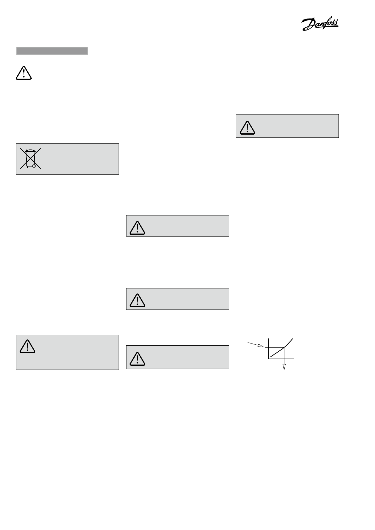
AVQM, AVQMT – PN16 (DN 15-32) / PN25 (DN 15-50)
No
中文
安全注意事项
为避免人员受伤和设备损坏,在安装和
调试前请务必仔细阅读并遵守本说明。
安装、启动、维护必须由专业人员进行。
在安装和维护控制器之前,系统必须先进行:
- 卸压,
- 冷却,
- 排空
- 清洁。
请遵循系统安装商或系统操作员的指示。
处置
本产品在回收或弃置之前,应先
拆卸并对
请始终遵循当地的弃置处理相关
规定。
零部件进行归类。
本产品的使用场合
该控制器配合电动驱动器 AMV(E) 使 用 ,用 于 供
暖、区域供热和制冷系统中水以及乙二醇和水混
合物的流速和温度控制。
AVQM PN 16 可以组合电动驱动器 AMV( E) 10/13
(仅 DN15)、AMV(E) 20/23、AMV 20/23 SL、
AMV(E) 30/33、AMV 30、AMV 15 0。
AVQM(T) PN 25 可以组合电动驱动器 AMV(E)
10/13(仅 DN15)、AMV(E) 20/23、AMV 20/23
SL、AMV(E) 30/33、AMV 30、AMV 150。
AVQMT PN 25 可以组合温控器 AV T 或安全温度
监 示 器(温 控 器)STM。
产品标签上的技术参数确定了使用情况。
安装位置和安装方案
AVQM(T) 供水和回水安装 ❸
阀门安装 ❹
1. 组装之前清洁管道系统。
2. 强烈建议将过滤器 ① 安装在控制器前侧。
3. 安装阀门
• 必须参照产品标签 ② 或阀门 ③ 上标明的
流动方向。
• 点焊到管道④ 上。
进行最终焊接之前,取下阀门和密封件。⑤⑥
如果不取下阀门和密封件,焊接高温可能会
导致其损坏。
• 管道上的法兰 ⑦ 必须保证平行,且密封面
必须清洁和无损伤。
分 3 步将法兰中的螺丝拧紧至最大扭矩
(50 Nm)。
4.
注意:
必须避免管道机械荷载作用在阀体上 ⑧。
电动驱动器的安装 ❺
将电动驱动器 AMV(E) 放 在 阀 门 上 ,使 用 扳 手 SW
32 拧紧连接螺母。
扭矩 25 Nm。
其他详细信息:
请参见电动执行器
温控器的安装 ❻
(仅 适 用 于
将温控器 AVT 或 STM 放 在 膜 片 上 ,使 用 扳 手 SW
50 拧紧连接螺母。
扭矩 35 Nm。
AVQMT
组装
允许温度 ❶
其他详细信息:
请参见温 控器
允许安装位置 ❷
① 介质温度 <10 0°C:任 何 方 位
② 介质温度 10 0°C - 130°C:水 平 且 控 制 阀 朝 上
③ 介质温度 >130 ° - 150°C:控 制 阀 朝 上
其他详细信息:
请参见电动执行器
书 。对 于
温控器
AVT
的说明书。
AVQMT
或安全温度监示器(温控器)
AMV(E )
控 制 器 ,还 请 参 见
的说明
STM
保温 ❼
对于不超过 10 0°C 的 介 质 温 度 ,还 可 以 对 压 力 驱
动器 ① 进行保温。
不允许对电动执行器
保温。
启动 ❽
给系统注水,首次启动
1. 打开系统中的阀门。
2. 慢慢打开供水管道上的关断装置 ①。
3. 慢慢打开回水管道上的关断装置 ②。
控 制 器)
AVT 或 STM
AMV(E )
② AM V(E)
的说明书。
的说明书。
进行
泄漏与压力试验
请勿使用 16 bar 以上的压力对关闭的控制阀进
行试验。否则阀门可能损坏。
安装电动驱动器之前,应进行压力试验。这样会
保证 阀门打开。
压力试验之前,逆时针转动以打开可调节流量
限制器。
(+/-) 连接 ③
提高。
违规有可能导致驱动器或阀门发生损坏。
整个系统的压力试验必须根据制造商说明进行。
最大试 验 压 力为:1.5 × PN
PN – 请参见 产品标 签!
处的压力必须缓慢
停止运行
1. 慢慢关闭供水管道上的关断装置 ①。
2. 慢慢关闭回水管道上的关断装置 ②。
最大流量限制 ❾
流速通过限制控制阀的行程进行调节。
有两种可能性:
1. 使用流量调节曲线进行调节,
2. 使 用热量计进行调节。
预先条件
拆除电动驱动器 AMV(E) 时应执行该设定。
如果安装了电动驱动器,该驱动器的阀杆必须
缩回。
使用流量调节曲线进行调节 ❿
要进行调节,系统无需处于活动状态。
1. 拆除密封环 ①
2. 将可调节流量限制器顺时针转动至其止动位
置 ,关 闭 控 制 阀 ②。
3. 选择图中的流量调节曲线
(对 于 PN 16 请参见 ⓬)
(对 于 PN 25 请参见 ⓭)
所需流量
转动设定螺线的圈数
3. 按照确定的圈数逆时针转动可调节流量限制
器 ,打 开 控 制 阀 ③。
20 | © Danfoss| 2020.03
VI.LI.F3.3F
Page 21
AVQM, AVQMT – PN16 (DN 15-32) / PN25 (DN 15-50)
4. 将流量限制螺母下端与外壳上的标记进行比
较,可以看到设定指示。
5. 阀行程的设定完成,继续第 2 步“ 使 用 热 量
计 进 行 调 节 ”。
如 果 系 统 正 在 运 行 ,可 以 使 用 热 量 表
协助进行设定校核。
流量调节曲线 - PN 16 ⓬
流量调节曲线 - PN 25 ⓭
使用热量计进行调节
系统中的所有装置 ❽ 均须 完全打开。
- 逆时针转动 ❿③ 会提高流速
- 顺时针转动 ❿③ 会降低流速
调节完成后:
1. 如 果 尚 未 完 成 ,则 安 装 驱 动 器 ❺①
设定完成。
2. 将密封环组装到可调节流量限制器之后 ⓫①
设定可能已经密封 ⓫②。
系统必须正在 运 行。
温度设定
(仅 适 用 于
请参见温 控器 AV T 或 安 全 温 度 监 示 器(温 控 器)
STM 的说 明书。
AVQMT
控 制 器)
尺 寸 ,重 量 ⓮
VI.LI.F3.3F
© Danfoss | 2020.03 | 21
Page 22

Danf
already on order pro
All trademarks in this material are property of the respec
AVQM, AVQMT – PN16 (DN 15-32) / PN25 (DN 15-50)
oss can accept no responsibility for possible errors in catalogues, brochures and other printed material. Danfoss reserves the right to alter its products without notice. This also applies to products
vided that such alterations can be made without subsequential changes being necessary eady agreed.
22 | © Danfoss | DHS-SRMT/SI | 2020.03
tive companies. Danfoss and the Danfoss logotype are trademarks of Danfoss A/S. All rights reserved.
VI.LI.F3.3F/73695110
 Loading...