

Page 1
Data sheet
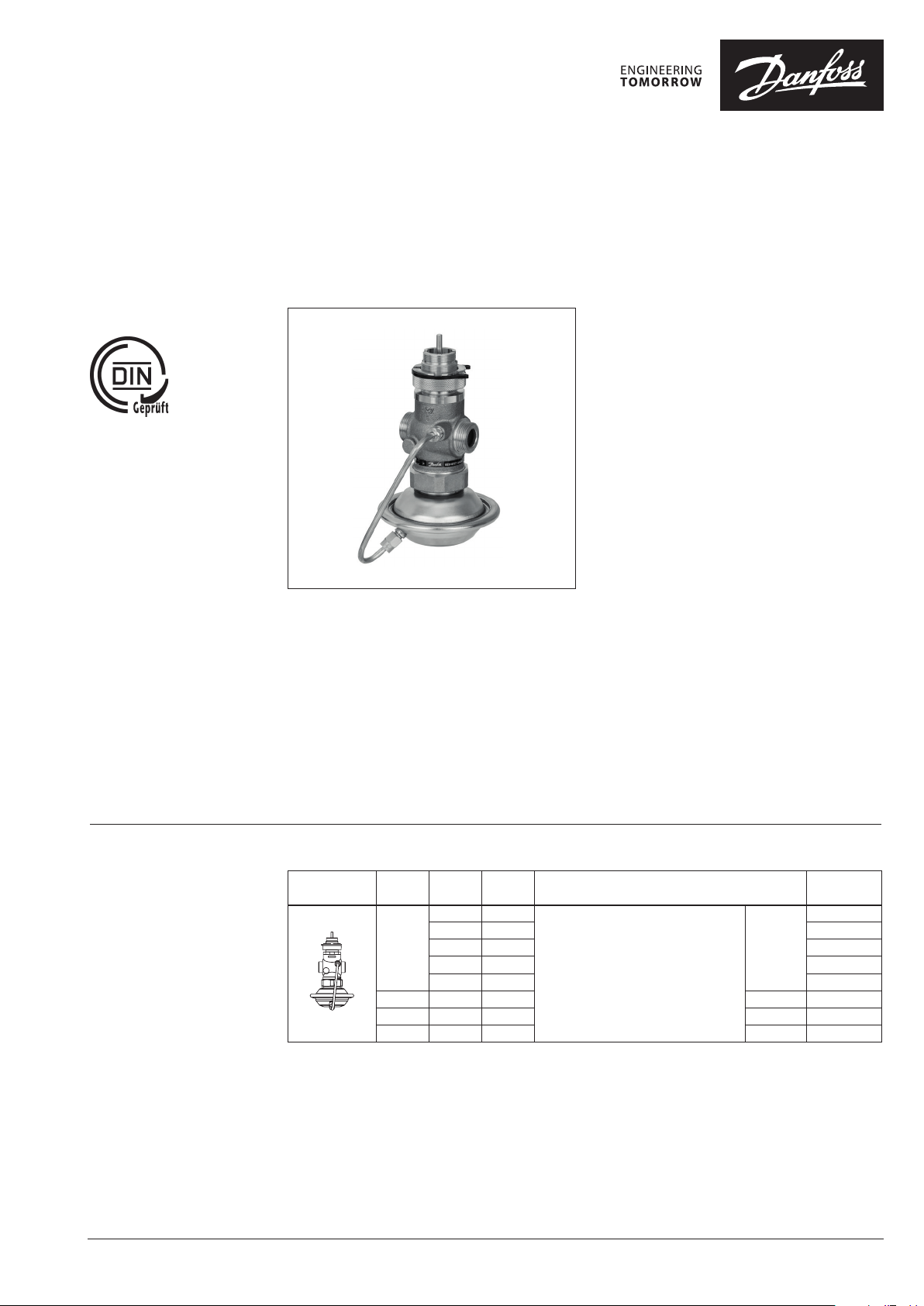
Pressure independent control valve with integrated flow limiter
AVQM (PN 16) - return and flow mounting
Description
AVQM is a self-acting flow controller with
integrated control valve developed for the
use in district heating / cooling systems. The
controller prevents flow to exceed set max
flow. In a combination with electrical actuators
AMV(E) and ECL electronic controllers the flow
and temperature can be controlled to achieve
highest energy savings.
AVQM has a control valve with adjustable flow
limiter, connection neck for electrical actuator and
a pressure actuator with one control diaphragm.
Controllers are used together with Danfoss
electrical actuators:
• AMV 150 1)
• AMV(E) 10 1) / AMV(E) 20 / AMV(E) 30
• AMV(E) 13 1) / AMV(E) 23 / AMV(E) 33 with
spring return function
• AMV 20 SL / AMV 23 SL / AMV 30 SL with stroke
limitation
1)
AMV 150 / AMV(E) 10 / AMV(E) 13 can be combined w ith DN 15
controller only.
AVQM combined with AMV(E) 13, AMV(E) 23 (SL)
or AMV(E) 33 (SL) has been approved according
to DIN 32730.
Main data:
• DN 15-32
• kVS 0.4-10 m3/h
• Flow range 0.015-6.0 m3/h
• PN 16
• Differential pressure over control valve ∆p
0.2 bar
MCV
• Temperature:
Circulation water / glycolic water up to 30 %
2 … 150 °C
• Connections:
Ext. thread (weld-on, thread and flange
tailpieces)
Ordering
Example:
Flow controller with integrated
control valvefor flow rate 0.7
m3/h; PN 16; T
thread
150 °C; ext.
max
- 1× AVQM DN 15 controller
Code No: 003H 6735
Option:
- 1× Weld-on tailpieces
Code No: 003H690 8
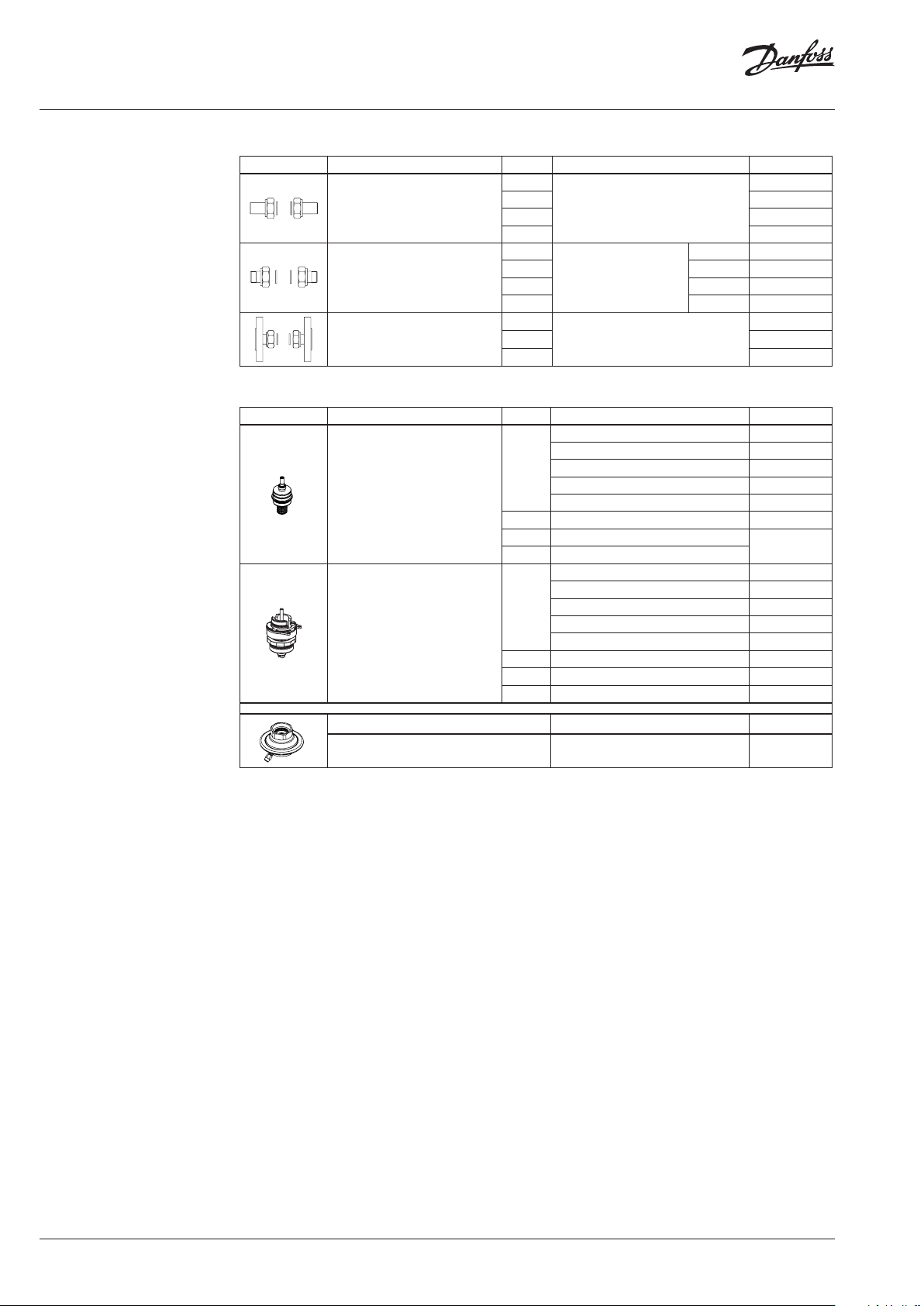
AVQM Controller
Picture
DN Q
(mm) (m3/h) (m3/h)
15
20 3.5 6.3
25 4.5 8.0
32 6 10
max
0.18 0.4
0.4 1.0 003H 6734
0.9 1.6 003 H6735
1.6 2.5 003H6736
2.4 4.0 003H6737
k
VS
Connection Code No.
Cylindr. ext. thread acc. to ISO 228 / 1
G ¾ A
G 1 A
G 1¼ A
G 1¾ A
003H 6733
003H6738
003H 6739
00 3H674 0
The controller will be delivered
completely assembled, inclusive
impulse tube between valve and
actuator. Electrical actuator
AMV(E) must be ordered
separately.
© Danfoss | 2019.02 VD.DB.V9.02 | 1
Page 2
Data sheet AVQM (PN 16)
Ordering (continuous)
Accessories
Picture Type designation DN Connection Code No.
15
Weld-on tailpieces
External thread tailpieces
Flange tailpieces
20 003H6909
25 00 3H6910
32 0 03 H69 11
15
20 R ¾ 003H6903
Conical ex t. thread acc. to
25 R 1 003H6904
32 R 1¼ 003H6905
15
20 003H 6916
25 0 03H6 917
EN 10226 -1
Flanges PN 25, acc. to EN 1092-2
-
R ½ 003H6902
Service kits
Picture Type designation DN kVS (m3/h) Code No.
0.4 003H6861
1.0 003H6862
15
Valve insert
20 6.3 003H6996
25 8.0
32 10
15
Control valve insert
20 6.3 003H 6891
25 8.0 003H68 92
32 10 003H6795
1.6 003H6863
2.5 003H6864
4.0 003H6865
0.4 003H6886
1.0 0 03H6887
1.6 003H6888
2.5 003H6889
4.0 003H6890
003H6908
003H 6915
003H6867
Type designation Δp setting range (bar) Code No.
Actuator 0.2 003H6825
2 | VD.DB.V9.02 © Danfoss | 2019.02
Page 3
Data sheet AVQM (PN 16)
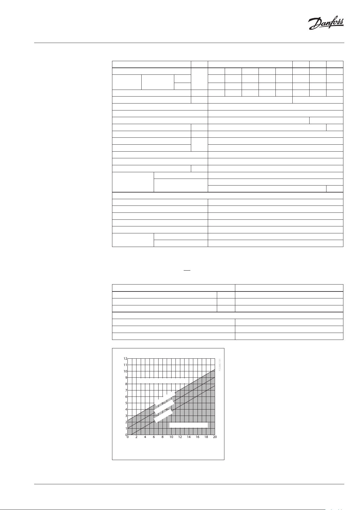
Technical data
Valve
Nominal diameter DN 15 20 25 32
k
value of dp controller
VS
Range of max.
flow setting
p
= 0.2 bar
MCV
Available ∆p required for Q
Q
Q
max
min
max
m3/h
2)
Stroke mm 5 7
Control valve authority 1 (100%) in the range of flow setting
Control characteristic Logarithmic
Cavitation factor z ≥ 0.6 ≥ 0.55
Leakage acc. to standard IEC 534 % of k
Nominal pressure PN 25
Min. differential pressure
Max. differential pressure 12
Medium Circulation water / glycolic water up to 30 %
Medium pH Min. 7, max. 10
Medium temperature ºC 2 … 150
valve External thread
Connections
tailpieces
Materials
Valve body Red bronze CuSn5ZnPb (Rg5)
Valve seat Stainless steel, mat. No. 1.4571
Valve cone Dezincing free brass CuZn36Pb2As
Sealing DP EPDM
Sealing MC V Metal
Pressure relieve
system
Control valve insert Valve insert Piston
0.4 1.0 1.6 2.5 4.0 6.3 8.0 10
0. 015 0.02 0.03 0.07 0.07 0.16 0.2 0.16
0.18 0.4 0.9 1.6 2.4 3. 5 4.5 6.0
bar 0.4 0.4 0.5 0.6 0.6 0.5 0.5 0.6
VS
bar
≤ 0.02 ≤ 0.05
see remark
1)
Weld-on and external thread
Flange -
Note:
DP - diff. pressu re controller, MCV - control valve
2)
For flows smal ler than Q
->
p
max
min
2
Q
p
MCV
k
VS
Actuator
Typ e AVQM
Actuator size cm
Nominal pressure PN 16
Differential pressure over MCV - motorized control valve bar 0.2
Materials
Housing
Diaphragm EPDM
Impulse tube Copper tube Ø 6 × 1 mm
No Cavitation noise
T=150 °C
T=130 °C
T=80 °C
Cavitation noise
2
39
Zinc plated, DIN 1624, No. 1.0338
Manometric Pressure downstrem [bar]
Manometric Pressure upstrem [bar]
Cavitation area for cavitation factor z=0.6
VD.DB.V9.02 | 3© Danfoss | 2019.02
Page 4
Data sheet AVQM (PN 16)
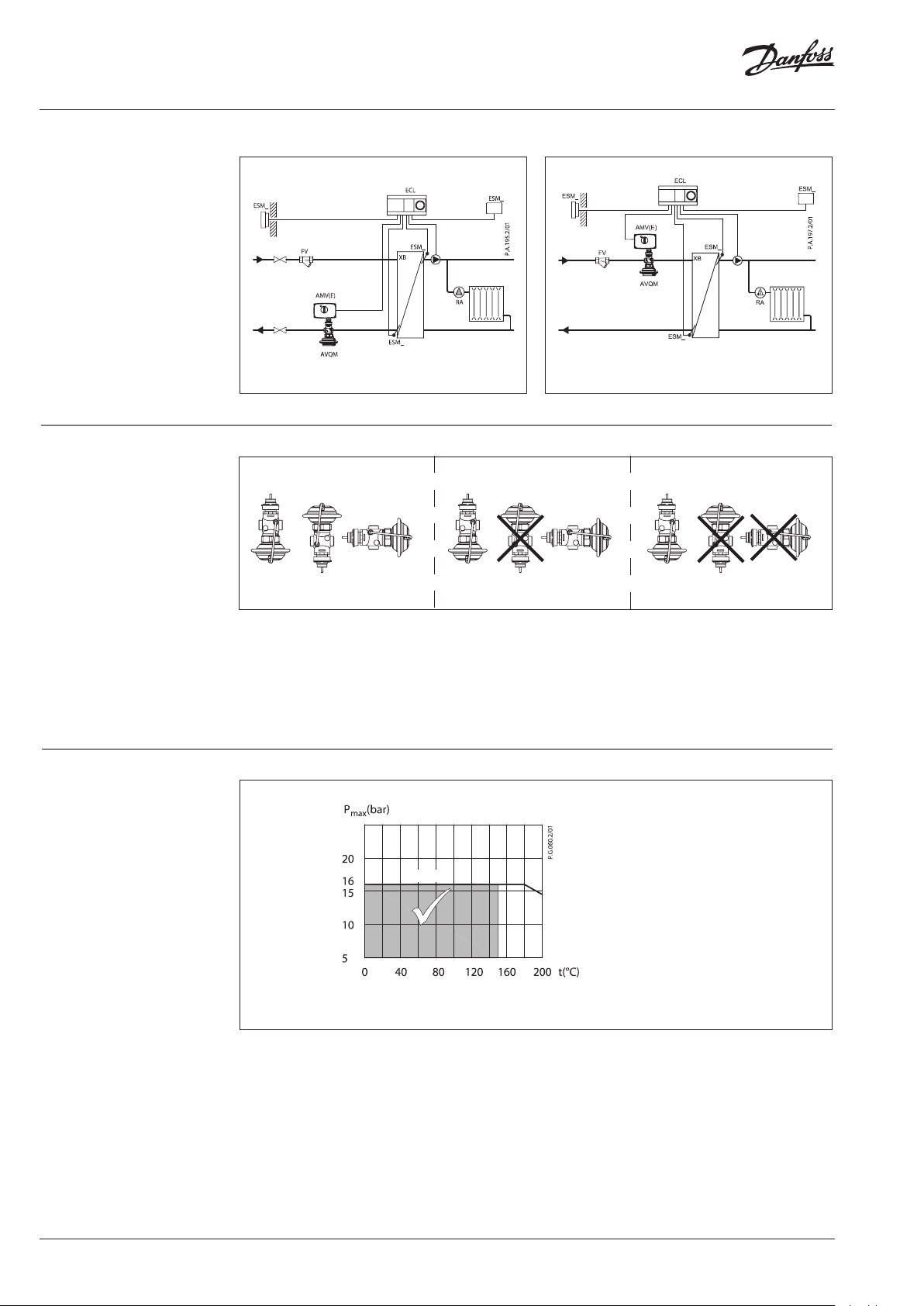
Application principles Flow mounting
Return mounting
Indirectly connec ted heating system
Indirectly connec ted heating system
Installation positions
Pressure temperature
diagram
Media temperature 100 °C Media temperature 130 °C Media temperature 150 °C
Electrical actuator
Note!
Installation positions for electrical actuators AMV(E)
have to be observed as well. Please see relevant
Data sheet.
PN 16
Maximum allowed operating pressure as a function of medium temperature (according to EN 1092-3).
CuSn5ZnPb (Rg5) PN 16
4 | VD.DB.V9.02 © Danfoss | 2019.02
Page 5
Data sheet AVQM (PN 16)
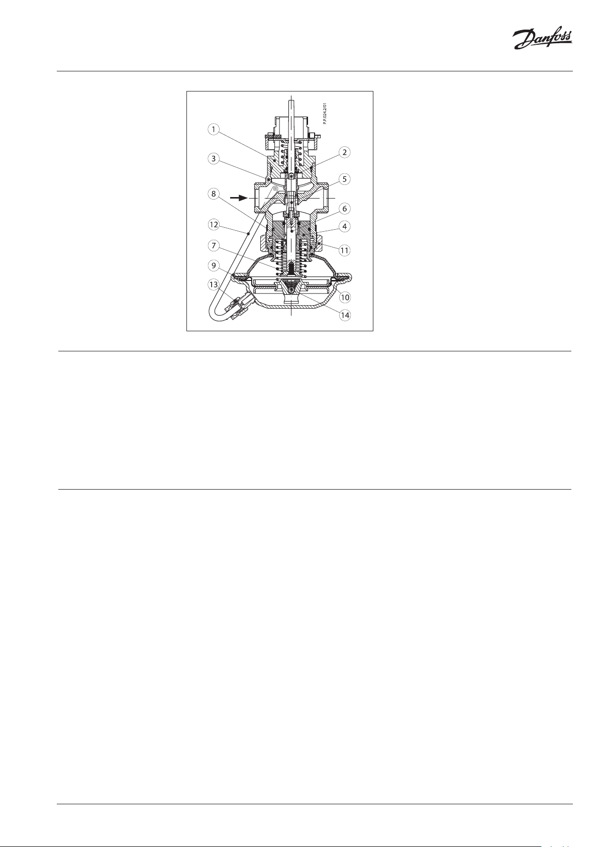
Design
1. Control valve insert
2. Adjustable flow restrictor
3. Valve body
4. Valve insert
5. Pressure relieved valve cone
6. Valve stem
7. Built-in spring for flow rate
control
8. Control drain
9. Actuator
10. Control diaphragm
11. Union nut
12. Impulse tube
13. Compression fitting for
impulse tube
14. Excess pressure safety valve
Function
Settings
Flow volume causes pressure drop across the
adjustable flow restrictor. Resulting pressures are
being transferred through the impulse tubes
and/or control drain in the actuator stem to the
actuator chambers and act on control diaphragm
for flow control. The flow restrictor diff. pressure
is controlled and limited by means of built-in
spring for flow control. Control valve closes
on rising differential pressure and opens on
falling differential pressure to control max flow.
Max flow limiting
Max flow limiting is being done by the
adjustment of the flow restrictor position. The
adjustment can be performed on the basis
of flow adjustment diagram (see relevant
instructions) and / or by the means of heat meter.
Additionally the electrical actuator will operate
from zero to set max. flow according to the load.
Controller is equipped with excess pressure
safety valve, which protects control diaphragm
for flow control from too high differential
pressure.
VD.DB.V9.02 | 5© Danfoss | 2019.02
Page 6
Data sheet AVQM (PN 16)
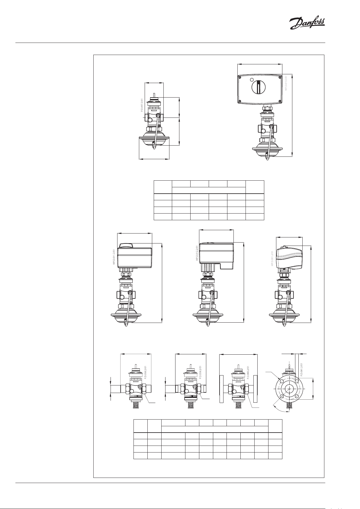
Dimensions
Ø 106
AVQM (DN 15-32)
121
L
1
H
H
DN
L H H
mm
H
1
15 65 97 72 289 1.9
20 70 97 72 289 1.9
25 75 97 75 292 2.0
32 100 97 76 293 2.5
121
Weight
2
155
AMV(E) 2./ 3. +
AVQM (DN 15-32)
(kg)
2
H
92
AMV(E) 10 +
AVQM (DN 15)
d
276
279
AMV(E) 13 +
AVQM (DN 15)
L
3
R
SW
SW d L1 2)L2L
1)
DN R
15 ⁄ 32 (G ⁄A) 21 13 0 120 139 65 14 4
20 ⁄ 41 (G 1A) 26 150 131 154 75 14 4
25 1 50 (G 1⁄A) 33 160 145 159 85 14 4
32 1⁄ 63 (G 1³⁄A) 42 - 177 18 4 10 0 18 4
1)
Conical ex t. thread acc. to EN 10226-1
2)
Flanges PN 25, acc. to EN 1092-2
L
2
L
1
SW
SW
k d
3
mm
AVQM (DN 15)
n
2
n
AMV 150 +
d
2
45°
277
k
6 | VD.DB.V9.02 © Danfoss | 2019.02
Page 7

Data sheet AVQM (PN 16)
VD.DB.V9.02 | 7© Danfoss | 2019.02
Page 8

Danf
already on order pro
All trademarks in this material are property of the respec
Data sheet AVQM (PN 16)
oss can accept no responsibility for possible errors in catalogues, brochures and other printed material. Danfoss reserves the right to alter its products without notice. This also applies to products
vided that such alterations can be made without subsequential changes being necessary eady agreed.
tive companies. Danfoss and the Danfoss logotype are trademarks of Danfoss A/S. All rights reserved.
© Danfoss | DHS-SRMT/SI | 2019.028 | VD.DB.V9.02
 Loading...