

Page 1
Data sheet
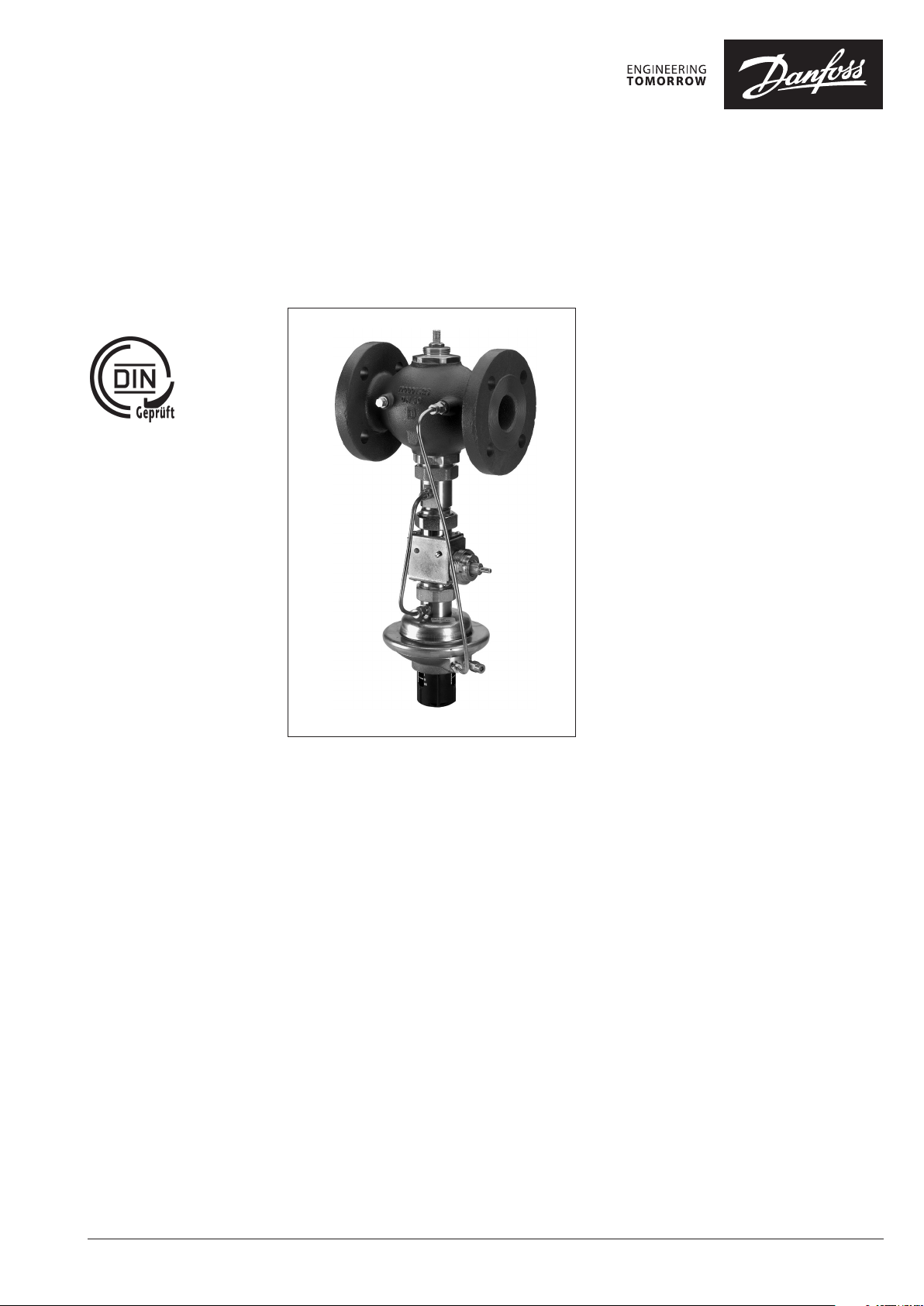
Differential pressure, flow and temperature controller (PN 25)
AVPQT - return mounting, adjustable setting
Description
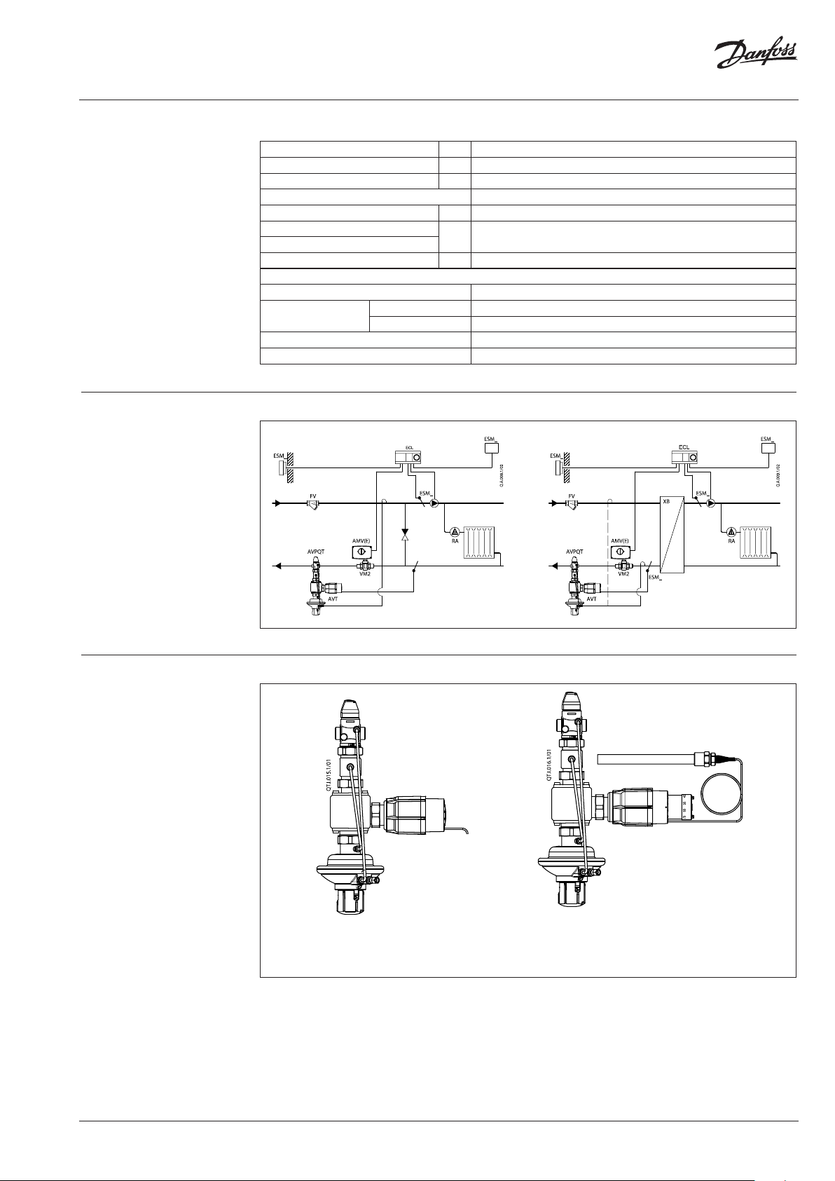
The AVPQT is a self-acting differential pressure,
flow and temperature controller primarily for use
in district heating systems. The controller closes
on rising differential pressure or temperature, or
when set max. flow is exceeded.
AVPQT controller can be combined with AVT or
STM thermostatic actuators.
The AVPQT controller have a control valve with
adjustable flow restrictor, combination piece
with connection neck for thermostat, an actuator
with two control diaphragms and handle for
differential pressure setting.
The controllers combined with AVT and STM
thermostats are type-tested acc. to EN 14597.
Controllers combined with STM thermostats
protect systems against exceeding temperatures.
Applications:
- District heating systems acc. to DIN 4747
- Heating systems acc. to EN 12828 (DIN 4751)
and EN 12953-6 (DIN 4752)
- Water heating systems for drinking and
industrial waters acc. to DIN 4753.
Main data:
• DN 15-50
• kVS 4.0-25 m3/h
• Flow range: 0.07-15 m3/h
• PN 25
• Setting range: 0.2-1.0 bar
• Flow restrictor ∆pb: 0.2 bar
• Setting ranges:
- AVT:
−10 … 40 °C / 20 … 70 °C / 40 … 90 °C / 60 … 110 °C
and
10 … 45 °C / 35 … 70 °C / 60 …
- STM:
20
…
75 °C / 40
• Temperature:
- Circulation water / glycolic water up to 30 %:
2 … 150 °C
• Connections:
- Ext. thread (weld-on, thread and flange
tailpieces)
- Flange
…
95 °C / 30
100 °C / 85
…
110 °C
…
125 °C
© Danfoss | 2017.01
VD.DC.M5.02 | 1
Page 2
Data sheet AVPQT (PN 25)
Ordering
Example:
AVT (or STM) / AVPQT controller:
Differential pressure; flow and
temperature controller; return
mounting; DN 15; kVS 4.0; PN 25;
setting range 0.2-1.0 bar;
T
150 °C; ext. thread;
max
- 1× AVPQT DN 15 controller
Code No: 003H6807
- 1× AVT thermostatic actuator,
40 … 90 °C
Code No: 065-0598
- 1× Impulse tube set AV R ⁄
Code No: 003H6852
Option:
- 1× Weld-on tailpieces
Code No: 003H6908
The controller AVPQT will be
delivered completely assembled,
inclusive combination piece and
impulse tubes between valve and
actuator. Thermostatic actuator
AVT will be delivered separately.
External impulse tube (AV) must be
ordered separately.
In case of safety temp. monitoring
STM should be ordered instead of
AV T.
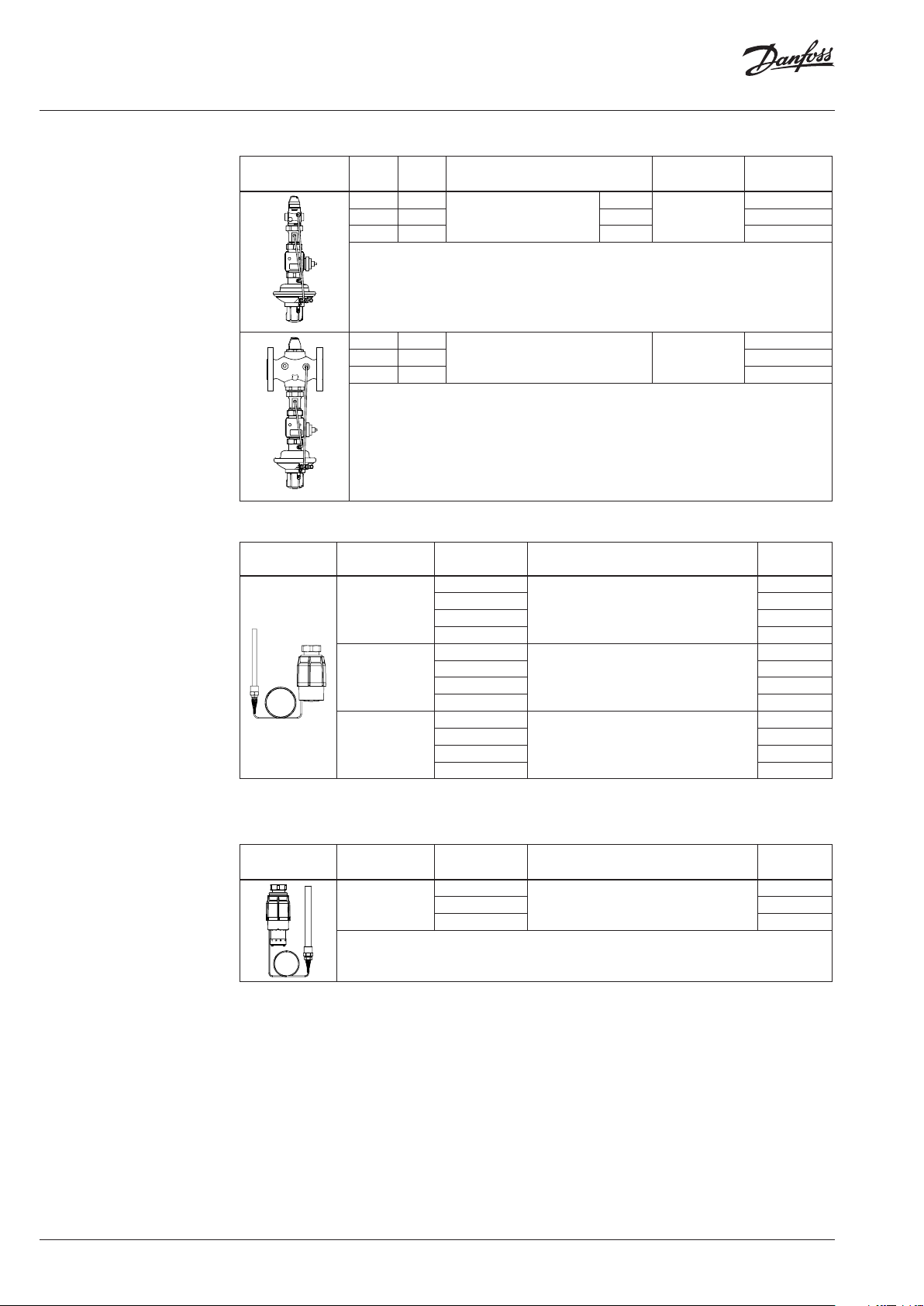
AVPQT Controller (return mounting)
Picture
DN k
(mm) (m3/h)
15 4.0
20 6.3 G 1 A 003H6808
25 8.0 G 1¼ A 003H6809
32 12. 5
40 20 00 3H 6811
50 25 00 3H6812
VS
AVT Thermostatic actuator
Picture For valves
DN 15-2 5
DN 32-50
DN 15- 50
1)
conic male thre ad EN 10226-1
2)
without immersion pocket
Connection
Cylindr, ext, thread acc, to ISO
Setting range
–10 … +40
20 … 70 065-0597
40 … 90 065-0598
60 … 110 065-0599
−10 … +4 0
20 … 70 065-0601
40 … 90 065-0602
60 … 110 065-0603
10 … 45
35 … 70 065-0605
60 … 100 065-0606
85 … 12 5 065-0607
228/1
Flanges PN 25, acc, to EN 1092-2 0. 2-1.0
Temperature sensor with brass immersion
(°C)
pocket, length, connection
255 mm, R ¾
Δp setting range
G ¾ A
170 mm, R ½
210 mm, R ¾
1)
1)
1) 2)
(bar)
0. 2-1.0
Code No,
003H68 07
003 H6810
Code No.
065-0596
065-0600
065-0604
2 | VD.DC.M5.02
STM Safety temperature monitor (actuator)
Picture For valves
1)
conic male thre ad EN 10226-1
DN 15- 50
Limit range
(°C)
30 … 11 0
20 … 75 065-0609
40 … 95 065-0610
Temperature sensor with brass immersion
pocket, length, connection
210 mm, R ¾
1)
© Danfoss | 2017.01
Code No.
065-0608
Page 3
Data sheet AVPQT (PN 25)
Ordering (continuous)
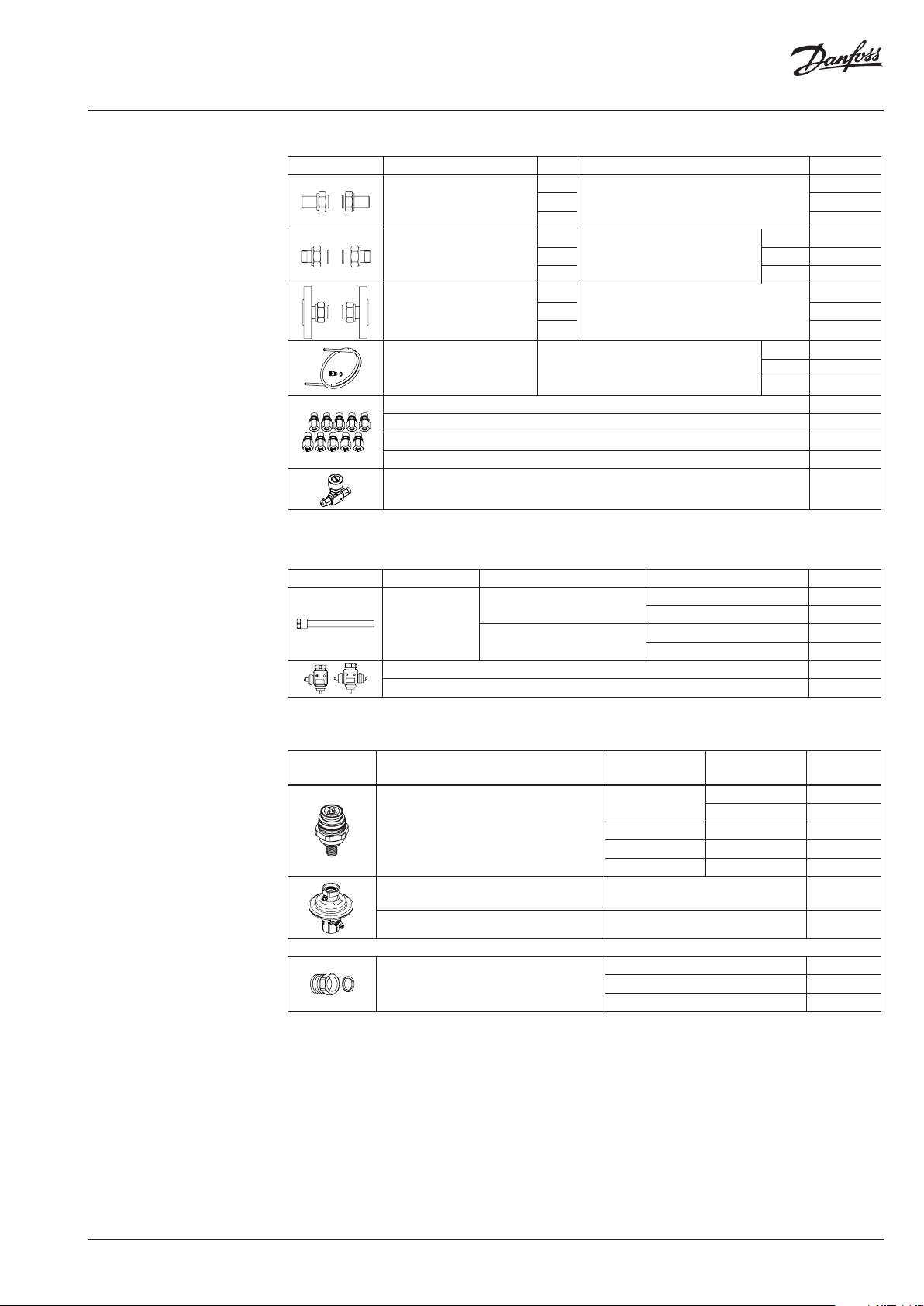
Accessories for AVPQT
Picture Type designation DN Connection Code No.
15
Weld-on tailpieces
20 003H6909
-
25 00 3H6910
External thread tailpieces
15
20 R ¾ 003H6903
25 R 1 003H6904
Conical ex t. thread acc. to
EN 10226-1
R ½ 003H6902
15
Flange tailpieces
20 003H6916
Flanges PN 25, acc. to EN 1092-2
25 0 03H6 917
Description:
Impulse tube set AV
- 1× copper tube Ø6 × 1 × 1500 mm
- 1× compression t ting 1) for imp. tube
connection to pipe Ø6 × 1 mm
1)
10 compression fittings for imp. tube connection to pipe, Ø6 × 1 mm R ⁄ 003H6857
1)
10 compression fittings for imp. tube connection to pipe, Ø6 × 1 mm R ⁄ 003H6858
1)
10 compression fittings for imp. tube connection to pipe, Ø6 × 1 mm R ½ 003H6859
1)
10 compression fittings for imp. tube connection to actuator, Ø6 × 1 mm G ⁄ 003 H6931
R ⁄ 003H6852
R ⁄ 003H 6853
R ½ 003H6854
Shut off valve Ø6 mm 003H0276
1)
Compression fitting consists of a nipple, compression ring and nut.
Accessories for thermostats
Picture Type designation For controllers Material Code No.
Brass 06 5-4 414
Brass 065 -4416
Immersion pocket
PN 25
AVT / AVPQT DN 15-25
AVT / AVPQT DN 32-50
STM / AVPQT DN 15-50
Stainless steel, mat. No. 1.4571
Stainless steel, mat. No. 1.4435
Combination piece K2 003H6855
Combination piece K3 003H6856
1)
Not for AVT the rmostatic actuator code nu mbers: 065-0604, 065-0605, 065-0606, 065-0607
003H6908
003H6 915
065- 4415
06 5-4 417
1)
1)
1)
1)
Service kits
Picture Type designation DN
Valve insert
Type designation
Actuator with adjustable handle 0. 2-1.0 003H6842
Housing of sensor stuffing box
k
VS
(m3/h)
15
2.5 003H6864
4.0 003H6865
Code No.
20 6.3 003H6866
25 8.0 003H6867
32 / 40 / 50 12.5 / 20 / 25 003H6868
∆p setting range
(bar)
Code No.
for sensors
AVT R ½ 065-4420
AVT R ¾ 065-4421
© Danfoss | 2017.01
VD.DC.M5.02 | 3
Page 4
Data sheet AVPQT (PN 25)
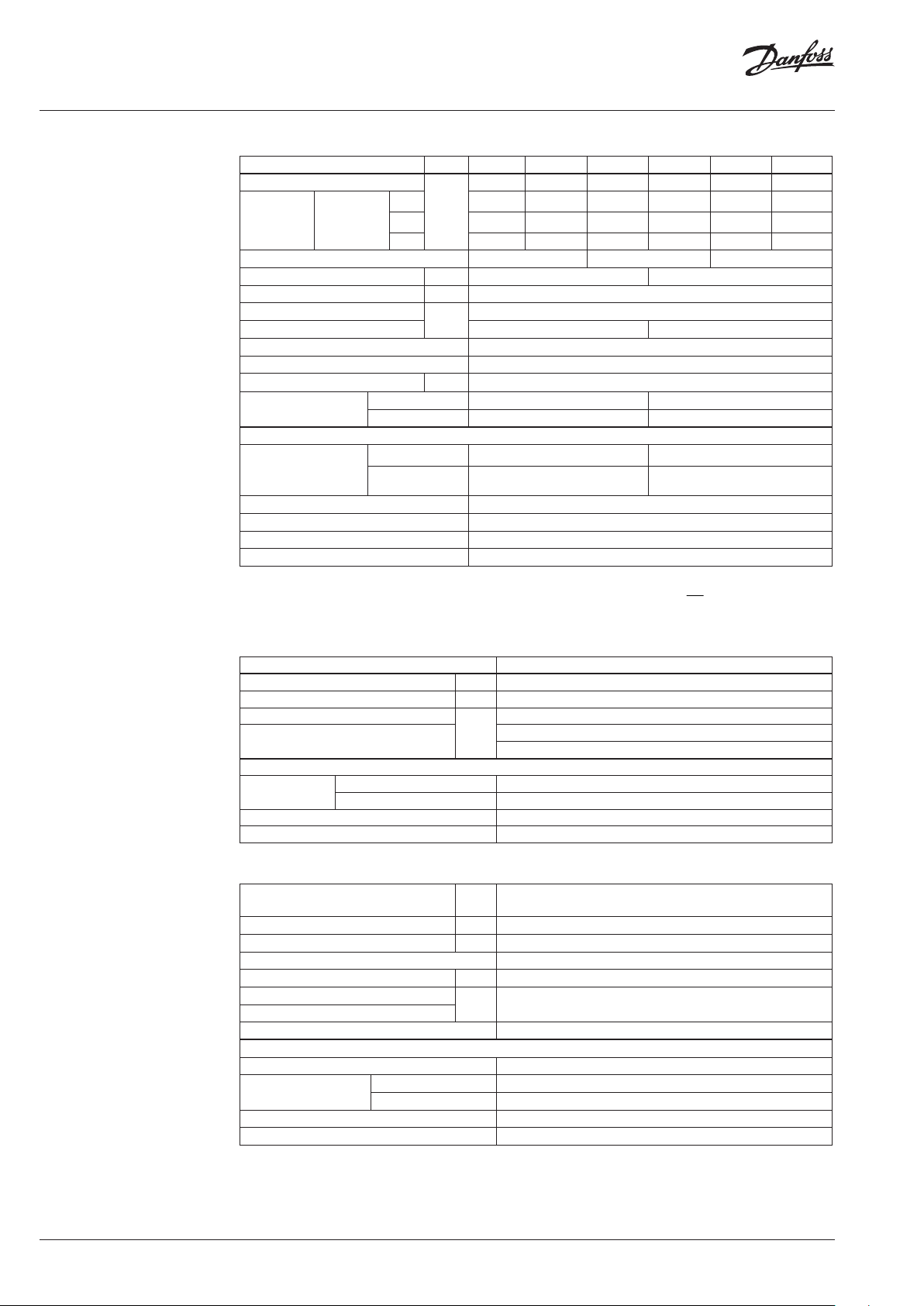
Technical data
Valve
Nominal diameter DN 15 20 25 32 40 50
kVS value
from
Range of max.
flow setting
∆pb 1) = 0.2 bar
m3/h
to
3)
to
Cavitation factor z ≥ 0.6 ≥ 0.55 ≥ 0.5
Leakage acc. to standard IEC 534 % of k
Nominal pressure PN 25
Min. differential pressure
Max. differential pressure 20 16
bar
Medium Circulation water / glycolic water up to 30 %
Medium pH Min. 7, max. 10
Medium temperature °C 2 … 150
Connections
valve External thread Flange
tailpieces Weld-on, external thread and flange -
Materials
thread Red bronze CuSn5ZnPb (Rg5) -
Valve body
flange -
Valve seat Stainless steel, mat. No. 1.4571
Valve cone Dezincing free brass CuZn36Pb2As
Sealing EPDM
Pressure relieve system
1)
∆pb - differe ntial pressure over flow rest rictor
2)
Depends o n the flow rate and valve kVS ; For Q
3)
Higher ma x flow are achieved at highe r differential pressu res over AVPQT controller. In general at p > 1-1 .5 ba r
4.0 6.3 8.0 12. 5 20 25
0.07 0.16 0.2 0.4 0.8 0.8
2.2 3.0 3.5 8.0 10 12
2.4 3.5 4.5 10 12 15
VS
≤ 0.02 ≤ 0.05
see remark
2)
Ductile iron
EN-GJS-400-18-LT (GGG 40.3)
Piston
= Q
-> ∆p
set
max
≥ 0.5 bar; For Q
min
< Q
->
set
p
max
min
2
Q
k
VS
p
b
Actuator
Typ e AVPQ T
Actuator size cm
Nominal pressure PN 25
Flow restrictor diff. pressure, ∆p
b
Di. pressure setting ranges and
spring colours
Materials
Actuator housing
Upper casing of diaphragm
Lower casing of diaphragm
Diaphragm EPDM
Impulse tube Copper tube Ø6 × 1 mm
bar
2
54
0.2
0. 2-1.0
yellow
Stainless steel, mat. No.1.4301
Dezincing free brass CuZn36Pb2As
AVT Thermostatic actuator
Setting range X
s
°C
Time constant T acc. to EN 14597 s max. 50 (170 mm, 210 mm), max. 30 (255 mm)
Gain K
s
mm/°K 0.2 (170 mm), 0.3 (210 mm), 0.7 (255 mm)
Max. adm. temperature at sensor 50 °C above maximum setpoint
Max. amb. temperature at thermostat °C 0 … 70
Nominal pressure sensor
Nominal pressure immerison pocket
PN 25
Capillary tube length 5 m (170 mm, 210 mm), 4 m (255 mm)
Materials
Temperature sensor Cooper
Ms design Brass, nickel-plated
Immersion pocket
1)
Stainless steel design Mat. No. 1.4571 (170 mm), mat. No. 1.4435 (210 mm)
Handle for temp. setting Polyamide, glass fiber-reinforced
Scale carrier Polyamide
1)
for sensor 170 and 210 mm
−10 … 40 / 20 … 70 / 40 … 90 / 60 … 110
10 … 45 / 35 … 70 / 60 … 100 / 85 … 125
4 | VD.DC.M5.02
© Danfoss | 2017.01
Page 5
Data sheet AVPQT (PN 25)
Technical data (continuous)
Application principles
The controller must be installed
in the return pipe only.
STM Safety temperature monitor (actuator)
Limit range X
Time constant T acc. to EN 14597 s ma x. 100
Gain K
Max. adm. temperature at sensor 80 °C above ma ximum setpoint
Max. amb. temperature at thermostat °C 0 … 70
Nominal pressure sensor
Nominal pressure immerison pocket
Capillary tube length m 5
Materials
Temperature sensor Cooper
Immersion pocket
Handle for temp. setting Polyamide, glass fiber-reinforced
Scale carrier Polyamide
s
s
Ms design Brass, nickel-plated
Stainless steel design mat. No. 1.4435
°C 20 … 75 / 40 … 95 / 30 … 110
mm/°K 0.3
PN 25
Combinations
AVT / AVPQT
- Differential pressure, flow and temperature controller
STM / AVPQT
- Differential pressure and flow controller with
safety temperature monitor
© Danfoss | 2017.01
VD.DC.M5.02 | 5
Page 6

Data sheet AVPQT (PN 25)
Installation positions
Differential pressure, flow and temperature
controller
Up to medium temperature of 100 °C the
controllers can be installed in any position.
Temperature sensor
The place of installation must be chosen in a way
that the temperature of the medium is directly
taken without any delay. Avoid overheating of
temperature sensor. The temperature sensor
must be immersed into the medium in its full length.
Temperature sensors 170 mm R½ and 210 mm R¾
- The temperature sensor may be installed in
any position.
For higher temperatures the controllers have
to be installed in horizontal pipes only, with a
pressure and temperature actuator oriented
downwards.
Temperature sensor 255 mm R¾
- The temperature sensor must be installed as
shown on the picture.
Pressure temperature
diagram
6 | VD.DC.M5.02
② EN-GJS- 400-18-LT (GGG 40.3) PN 25
① CuSn5ZnPb (Rg5) PN 25
Maximum allowed operating pressure as a function of medium temperature (according to EN 1092-2 and EN 1092-3).
© Danfoss | 2017.01
Page 7

Data sheet AVPQT (PN 25)
Flow diagram
Sizing and setting diagram
Relation between actual flow and number of revolutions on flow restictor. Values given are approximate.
DN 50 k
25
VS
12. 5
VS
DN 25 k
DN 20 k
DN 15 k
DN 40 k
20
VS
8.0
VS
6.3
VS
4.0
VS
DN 32 k
1 = 360 º
Flow can be adjusted by turning flow restrictor screw
counter-clockwise as shown in this diagram.
Water flow shown at dif ferential pressure across flow
Remark:
Controllers D N 40 and DN 50 have the same cur ve up to 9 revolutions.
restrictor 0.2 bar (20 kPa) and across the controller
from 0.5 bar (50 kPa) to 16/20 bar (1600/2000 kPa).
© Danfoss | 2017.01
VD.DC.M5.02 | 7
Page 8

Data sheet AVPQT (PN 25)
Sizing
- inderectly connected heating
system
Example
Motorised control valve (MCV) for indirectly
connected heating system requires differential
pressure of 0.3 (30 kPa) bar and flow less than
1150 l/h. Return temperature is limited to 70 °C.
Given data (AVPQT):
Q
= 1.15 m3/h (1150 l/h)
max
∆p
= 1.0 bar (100 kPa)
min
∆p
∆p
∆pb 1) = 0.2 bar (20 kPa)
Remark:
1)
∆pb is differe ntial pressure over flow rest rictor
= 0.05 bar (5 kPa)
exchanger
= 0.3 bar (30 kPa) selected
MCV
The differential pressure set value is:
∆p
∆p
∆p
= ∆p
set value
set value
set value
exchanger
= 0.05 + 0.3
= 0.35 bar (35 kPa)
+ ∆p
MCV
The total pressure loss across the controller is:
∆p
= ∆p
AVPQT
∆p
= 1.0 − 0.05 − 0.3
AVPQT
∆p
= 0.65 bar (65 kPa)
AVPQT
min
− ∆p
exchanger
− ∆p
Q
max
MCV
Possible pipe pressure losses in tubes, shut-off
fittings, heatmeters, etc. are not included.
kv value is calculated according to formula:
Q
k
v
max
pp
1.15
bAVPQT
0.20.65
kv = 1.7 m3/h
Solution:
The example selects:
- AVPQT DN 15, kVS value 4.0, with differential
pressure setting range 0.2-1.0 bar, flow setting
range 0.15-1.4 m3/h and
- AVT 170 mm, temperature setting range
40 … 90 °C.
p
p
min
AVPQ T
AVT
p
b
p
AVPQT
p
MCV
exchanger
8 | VD.DC.M5.02
© Danfoss | 2017.01
Page 9

Data sheet AVPQT (PN 25)
Design
1. Cover
2. Adjustable flow restrictor
3. Valve body
4. Valve insert
5. Pressure relieved valve cone
6. Valve stem
7. Control drain
8. Control diaphragm for flow
control
9. Control diaphragm for diff.
pressure control
10. Setting spring for diff.
pressure control
11. Handle for diff. pressure
setting, prepared for sealing
12. Union nut
13. Compression fitting for
impulse tube
14. Impulse tube
15. Upper casing of diaphragm
16. Lower casing of diaphragm
17. Thermostatic actuator AVT,
STM
18. Thermostat stem
19. Bellows
20. Setting spring for
temperature control
21. Handle for temperature
setting, prepared for sealing
22. Scale carrier
23. Capillary tube
24. Flexible protected pipe
(at 255mm only)
25. Temperature sensor
26. Immersion pocket
27. Combination piece K2
28. Connection piece V
29. Sensor stuffing box
30. Housing of sensor stuffing
box
31. Eccess pressure safety valve
32. Safety spring
AVT 255
AV T 170
AV T 210
STM
24
AVT
STM
© Danfoss | 2017.01
AVPQT
VD.DC.M5.02 | 9
Page 10

Data sheet AVPQT (PN 25)
Function
Differential pressure, flow and temperature
controller
Flow volume causes pressure drop across
the adjustable flow restrictor. Resulting
pressures are being transferred through the
impulse tubes and/or control drain in the
actuator stem to the actuator chambers and
act on control diaphragm for flow control.
The flow restrictor diff. pressure is controlled
and limited by means of built-in spring for
flow control. Control valve closes on rising
differential pressure and opens on falling
differential pressure to control max flow.
Pressure changes from flow and return pipes
are being transferred through the impulse
tubes to the actuator chambers and act on
control diaphragm for diff. pressure control.
The diff. pressure is controlled by means
of setting spring for diff. pressure control.
Control valve closes on rising differential
pressure and opens on falling differential
pressure to maintain constant differential
pressure.
Controller is equipped with excess pressure
safety valve, which protects control
diaphragm for diff. pressure control from too
high differential pressure.
Safety Temperature Monitor (STM)
- Function
The safety temperature monitor is
proportional temperature controller which
controls temperature and protects the system
against exceeding temperatures. The valve
cone is soft sealed and pressure relieved.
Handle for limit setting can be sealed.
- Extended safety function
If there is a leakage in the area of the
temperature sensor, the capillary tube, or the
thermostat, the valve closes by a safety spring
in the safety thermostat. In this case safety
temperature monitor (actuator) must be
replaced.
- Physical Function Principle
The safety temperature monitor operates
in accordance with the liquid expansion
principle. The temperature sensor, the
capillary tube and the bellows are filled with
liquid. As the temperature at the temperature
sensor rises, the liquid expands, the
thermostat stem moves out and closes the
valve.
Temperature Controller (AVT)
- Function
By increasing of medium temperature valve
cone moves towards the seat (valve closes),
by decreasing of medium temperature valve
cone moves away from the seat (valve opens).
Handle for temperature setting can be sealed.
- Physical Function Principle
Medium temperature changes cause pressure
changes in temperature sensor. Resulting
pressure is being transferred through the
capillary tube to the bellows. Bellows moves
thermostat stem and opens or closes the
valve.
In case the temperature at the temperature
sensor exceeds the adjusted set point, safety
temperature monitor interrupts energy
supply by closing the valve. As soon as the
temperature at the temperature sensor drops,
the valve opens automatically.
Settings Temperature setting (AVT)
Flow setting
Flow setting is being done by the adjustment of
the flow restrictor position. The adjustment can
be performed on the basis of flow adjustment
diagram (see relevant instructions) and/or by the
means of heat meter.
Differential pressure setting
Differential pressure setting is being done by
the adjustment of the setting spring for diff.
pressure control. The adjustment can be done by
means of handle for diff. pressure setting and/or
pressure indicators.
Temperature setting is being done by the
adjustment of the setting spring for temperature
control. The adjustment can be done by means
of handle for temperature setting and/or
temperature indicators.
Limit setting (STM)
Limit setting is being done by the adjustment of
the setting spring for temperature control. The
adjustment can be done by means of handle for
limit setting and/or temperature indicators.
10 | VD.DC.M5.02
© Danfoss | 2017.01
Page 11

Data sheet AVPQT (PN 25)
Adjustment diagram Differential pressure setting
Relation between scale figures and differential
pressure.
Note: The values given are approximate
Temperature setting
Relation between scale numbers 1-5 and closing
temperature.
Note: The values given are approximate
AVT Thermostat ... 210 mm
AVT Thermostat ... 255 mm
Note:
STM Safety temperature monitor (actuator):
temperature scale is already written on the product
© Danfoss | 2017.01
VD.DC.M5.02 | 11
Page 12

Data sheet AVPQT (PN 25)
Dimensions
H
150
Ø 76
AVT / AVPQT
H
STM / AVPQT
AVT
DN 15 20 25 32 40 50
H (AV T AVPQT ) mm 402 402 405 474 474 474
Weight (AVPQT) kg 3.0 3.3 3.5 8.2 11 12
Weight (AVT ) 1.3 (sensor 170 mm), 1.5 (210 mm), 1.6 (255 mm)
194
Ø 82
STM
12 | VD.DC.M5.02
DN 15 20 25 32 40 50
H (STM AVPQT) mm 402 402 405 474 474 474
Weight (AVPQT) kg 3.0 3.3 3.5 8.2 11 12
Weight (STM) 2.6 (sensor 210 mm)
© Danfoss | 2017.01
Page 13

Data sheet AVPQT (PN 25)
Dimensions (continuous)
174
SW 17
AV T 170
SW 25 (R ½)
SW 27 (R ¾)
R ½; R ¾
Ø 9.5
170
6
M14×1
AV T 170
Immersion p ocket
M 20×1 (R ½)
M 22×1 (R ¾)
Housing of sensor
stuffing box
Ø 12
SW 22
26 (R ½)
30 (R ¾)
R ½
SW 22
Combination piece K2
223
AV T 210
STM
85
Ø 16
M22×1
Immersion p ocket
109
Ø 19
215
10
SW 27
AVT 210 / STM
R ¾
SW 22
108
Combination piece K3
Ø 16
266
R ¾
AVT 255
109
L
3
L
2
L
1
d
2
n
d
SW
R
SW
k
SW
DN R
1)
SW d L
2)
L2L
1
mm
k d
3
2
n
15 ⁄ 32 (G ⁄A) 21 130 120 139 65 14 4
20 ⁄ 41 (G 1A) 26 15 0 131 154 75 14 4
25 1 50 (G 1⁄A) 33 160 145 159 85 14 4
32 1⁄ - 42 - 17 7 184 100 18 4
40 - - 47 - - 204 11 0 18 4
50 - - 60 - - 234 125 18 4
1)
Conical ex t. thread acc. to EN 10226-1
2)
Flanges PN 25, acc. to EN 1092-2
© Danfoss | 2017.01
VD.DC.M5.02 | 13
Page 14

Data sheet AVPQT (PN 25)
14 | VD.DC.M5.02
© Danfoss | 2017.01
Page 15

Data sheet AVPQT (PN 25)
© Danfoss | 2017.01
VD.DC.M5.02 | 15
Page 16

Danf
already on order pro
All trademarks in this material are property of the respec
Data sheet AVPQT (PN 25)
oss can accept no responsibility for possible errors in catalogues, brochures and other printed material. Danfoss reserves the right to alter its products without notice. This also applies to products
vided that such alterations can be made without subsequential changes being necessary eady agreed.
16 | VD.DC.M5.02
tive companies. Danfoss and the Danfoss logotype are trademarks of Danfoss A/S. All rights reserved.
© Danfoss | DHS-SRMT/SI | 2017.01
 Loading...