

Page 1
Data sheet
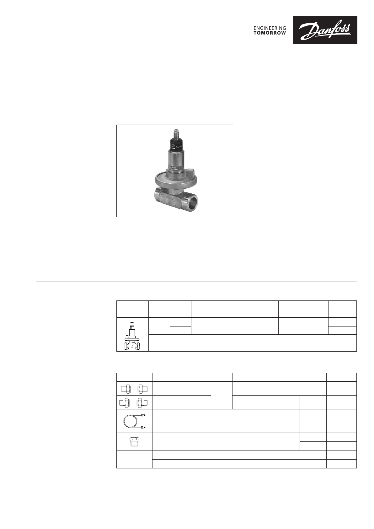
Differential pressure controller (PN 16)
AVPL - return mounting, adjustable setting
Description
Ordering
Example:
Differential pressure controller,
return mounting, DN 15, kvs 1.0,
PN 16, setting range 0.05 - 0.25 bar,
t
120 °C, ext. thread
max
- 1× AVPL DN 15 controller
Code No: 003L5030
Option:
- 1× Weld-on tailpieces
Code No: 003H6908
It can be used on primary side of house
substations for smaller systems such as one and
two-family houses.
The controller could be used to control the
differential pressure across radiator systems and
similar systems to keep a constant differential
pressure even with a variable system resistance
kva and/or supply pressure ∆p0.
Main data:
• DN 15
• kvs 1.0, 1.6 m3/h
• PN 16
• Setting range: 0.05-0.25 bar
(factory setting 0.1 bar)
AVPL is a self-acting differential pressure
controller primarily for use in district heating
systems. The controller closes on rising
differential pressure.
• Temperature:
- Circulation water / glycolic water up to 30%:
2 … 120 °C
• Connections:
- Ext thread (weld-on and thread tailpieces)
The controller has a control valve and an actuator
with one control diaphragm.
AVPL Controller
Picture
* Controller inc l. impulse tube set AH (1.5 m at kvs 1.0 and 2.5 m at kvs 1.6) and nipple G⁄ - R⁄ fo r impulse tube connecti on to pipe
DN
(mm)
15
kVS
(m3h)
1.0
1.6 003L5031
Ext. thread acc. to ISO 228/1 G ¾ A 0.05-0.25
Connection
∆p setting range
(bar)
Code No. *
003L5030
Accessories
Picture Type designation DN Connection Code No.
© Danfoss | 2020.03
Weld-on tailpieces
15
External thread tailpieces
Description:
Impulse tube set AH
Fitting for impulse tube connection to pipe
EPP insulation box
10 EPDM o-rings for impulse tube 003L8175
1)
The material fo r the insulation box is approve d according to the fire hazard classif ication B2, DIN 4102.
1)
- 1× copper tube Ø 3 × 1 mm
- 2× fitting for imp. tube connec tion
to actuator and pipe G /
Conical ex t. thread acc. to
EN 10226-1
- 003H6908
AI180286474027en-000902 | 1
R / 003H6902
1.5 m 003L3561
2.5 m 003L5043
5 m 003L3562
G / - R / 003L5042
G / - R ¼ 003L8151
00 3L817 0
Page 2
Data sheet Differential pressure controller AVPL (PN 16)
Technical data
Application principles
The controller AVPL could be
installed in the return pipeline only.
Nominal diameter DN
k
value m3/h 1.0 1.6
vs
Cavitation factor z 0.5
Nominal pressure PN 16
Max. differential pressure bar 4.5
Medium Circulation water / glycolic water up to 30%
Medium pH Min. 7, max. 10
Medium temperature
Connections
Materials
Valve body, etc. Dezincing free brass CuZn36Pb2As
Cone, seat, spindle and spring Stainless steel
Diaphragm and O-ring EPDM
Impulse tube
o
C 2 … 120
valve External thread
tailpieces Weld-on and external thread
Copper tube Ø 3 × 1 mm
Stainless steel tube Ø 0.8 × 0.2 × 800 mm
15
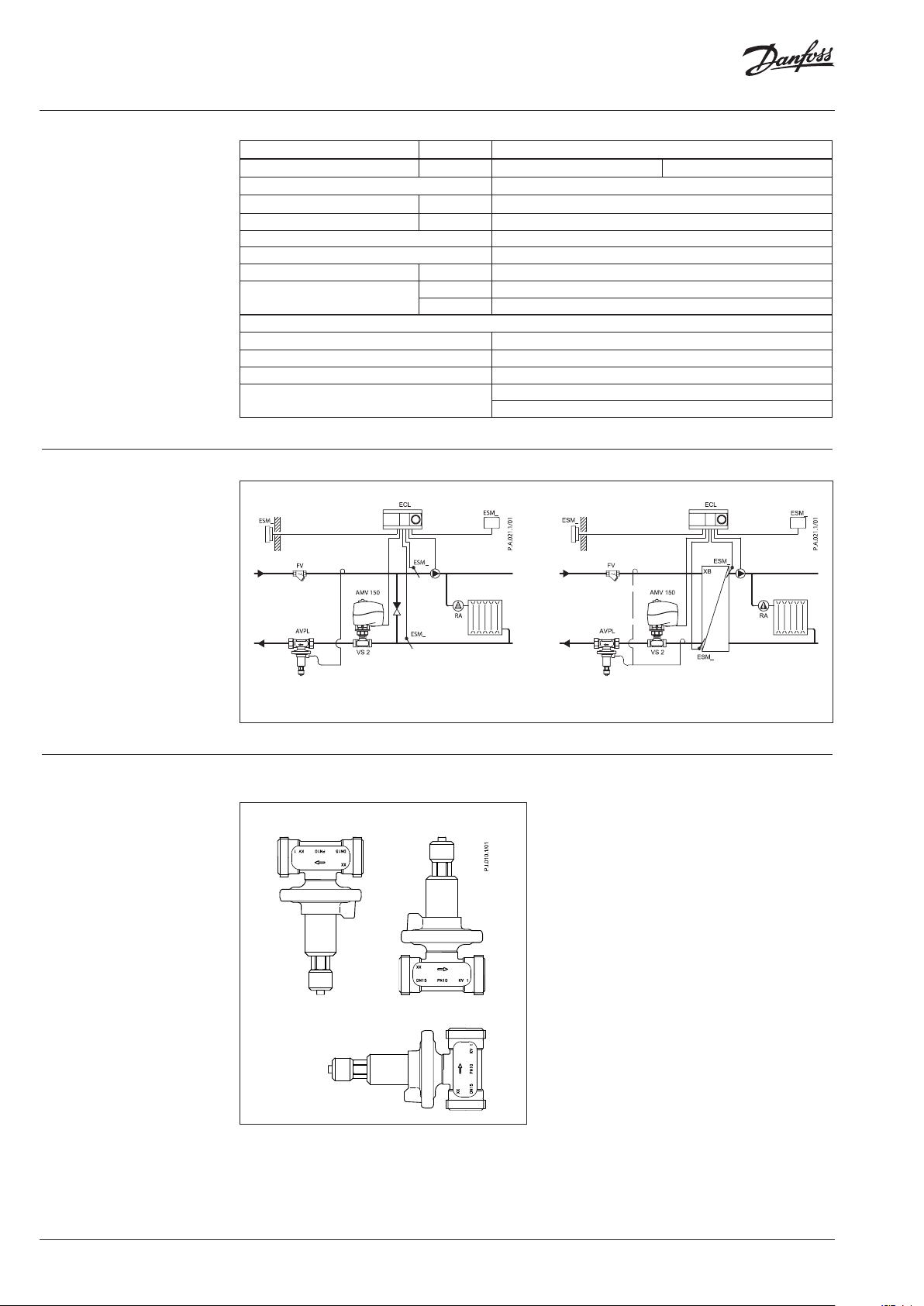
Installation positions
Direct-connected heating system Indirectly connected heating system
The controllers can be installed in any position.
2 | © Danfoss | 2020.03
AI180286474027en-000902
Page 3
Data sheet Differential pressure controller AVPL (PN 16)
Sizing
Considering the correlation between the
capacity of the system kva, the system flow Q
and the differential pressure ∆pa, the controller
setting ∆pi is determined by:
∆pi = ∆pa = (Q/kva)
2
Based on the stated differential pressure of
the district heating ∆po and the calculated
differential pressure of the system ∆pa, the
differential pressure across the controller valve is
expressed as:
∆pv = ∆po - ∆p
a
Finally, a check is required to ensure that the
actual capacity of the controller k
than its max. capacity k
kvv = Q / √∆pv ≤ k
vs
vs
is smaller
vv
Example:
A heating system with a number of parallel hot
surfaces.
Required flow:
Q = 0.24 m3/h
Total capacity of the system determined to be kva
= 0.6 m3/h.
Calculation of the differential pressure across the
system:
∆pa = (Q/ kva )2 = (0.24 /0.6)2 = 0.16 bar (16 kPa)
The differential pressure from the district heating
is stated to be:
∆po = 0.5 bar (50 kPa) min
Calculation of the differential pressure across the
controller valve:
∆pv = ∆po - ∆pa = 0.5 bar - 0.16 bar = 0.34 bar (34 kPa)
In this example the capacity of the controller
valve is:
kvv = Q/√∆pv = 0.24/√0.34 = 0.412 m3/h
which is less that the max. capacity of the
controller = kvs = 1.0 m3/h.
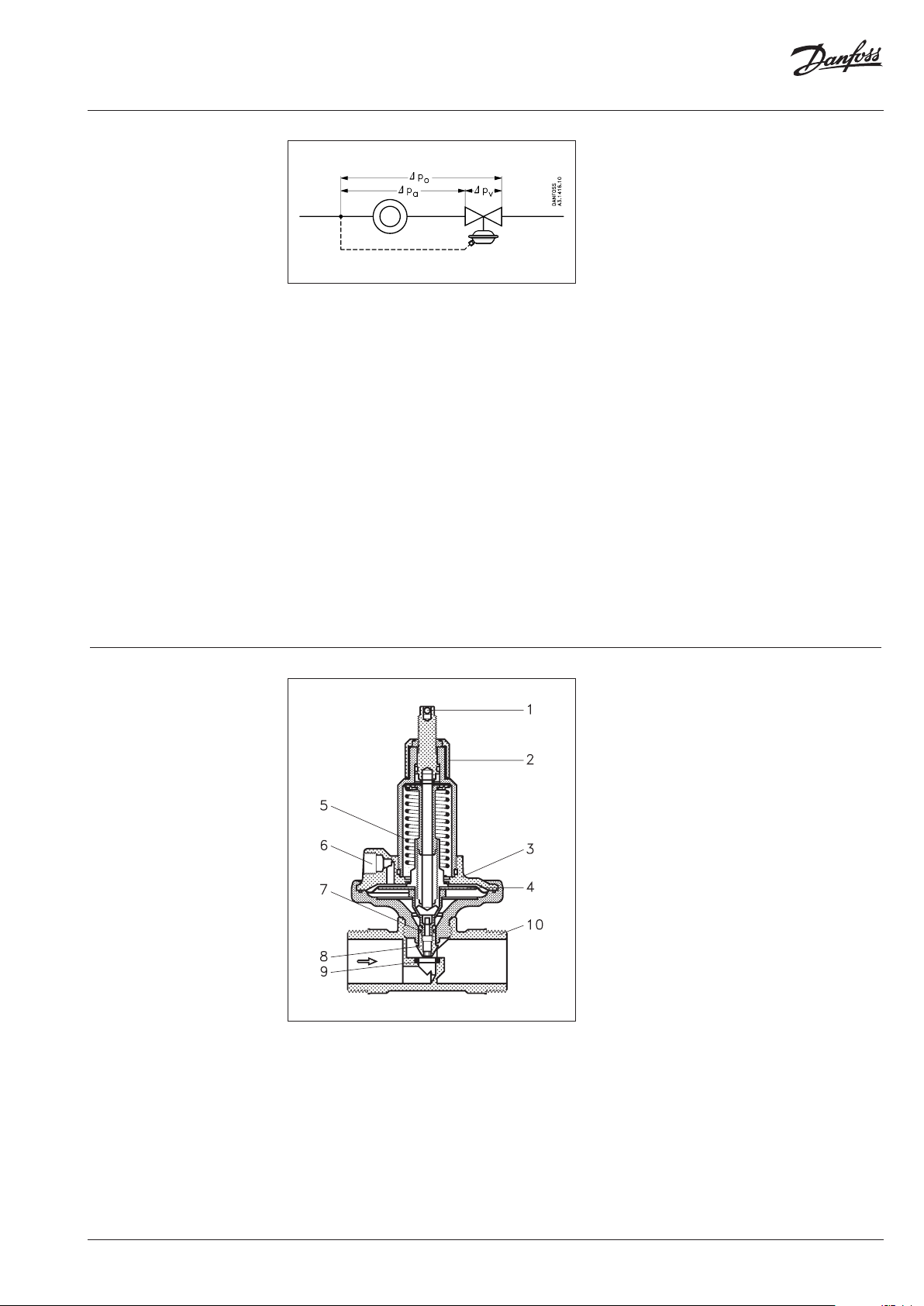
Design
1. Spindle for differential
pressure setting
2. Bushing
3. Actuator
4. Control diaphragm
5. Setting spring for diff.
pressure control
6. Connection for impulse tube
7. O-ring
8. Pressure relieved valve cone
9. Seat
10. Valve body
AI180286474027en-000902
© Danfoss | 2020.03 | 3
Page 4

Data sheet Differential pressure controller AVPL (PN 16)
2
va
a
k
Q
p
⎟
⎟
⎠
⎞
⎜
⎜
⎝
⎛
=∆
2
vv
v
k
Q
p
⎟
⎟
⎠
⎞
⎜
⎜
⎝
⎛
=∆
()
( )
2
vv
2
va
o
k1k1
p+∆
=
()
()
2
vvs
2
va
o
max
k1k1
p
Q
max
min
+
∆
=
Function AVPL is a proportional controller which operates
according to the following principle:
The degree of opening of the control valve / kv
value is proportional to the deviation between
the controlled and set differential pressure,
∆pa – ∆ps. Thus the resistance/kv value is adjusted
to the actual differential pressure ∆pv and
accordingly, the flow Q is adjusted so that the
desired differential pressure ∆pa is obtained
across the actual resistance kva in the system.
Differential pressure across the system
Differential pressure across the controller
Differential pressure from the district heating
Settings
∆po = ∆pa + ∆p
AVPL can be set to any differential pressure
v
within the range 5 kPa to 25 kPa (0.05 bar to
0.25 bar). The factory pre-setting of the AVPL is
10 kPa (0.1 bar), 1 kPa for each turn.
Rewritten the flow can be expressed as
The max. flow is limited by the min. differential
pressure of the district heating ∆p
capacity of the system k
capacity of the controller k
, and of the max.
va
max
.
v
vs
, the max.
o
min
Max. system flow:
The chosen deviation is large enough to ensure
a stable control and small enough to keep the
controlled differential pressure within acceptable
limits.
As mentioned above, the proportional effect
depends on the correlation between the
controller valve’s degree of opening and the
deviation between the controlled and set
differential pressure. Furthermore, the deviation
depends on the actual differential pressure
across the control valve and the actual control
setting.
The controller is designed in such a way that the
controlled and the set differential pressures are
equal when the flow is about 250 l/h for AVPL 1.0
and 400 l/h for AVPL 1.6 at nominal differential
pressure 50 kPa (∆pv). At min. and max. flow the
controlled differential pressure deviates from the
set pressure with ±1…3 kPa, depending on the
actual differential pressure and setting.
4 | © Danfoss | 2020.03
AI180286474027en-000902
Page 5

Data sheet Differential pressure controller AVPL (PN 16)
Dimensions
DN
15 (kvs 1.0)
15 (kvs 1.6) 0.69
L1
(mm)L2(mm)L3(mm)H(mm)D(mm)aISO 228/1bIS O 7/1
65 120 139 10 4 63 G ¾ A R ½
Weight
(kg)
0.64
Fittings
AI180286474027en-000902
© Danfoss | 2020.03 | 5
Page 6

Data sheet Differential pressure controller AVPL (PN 16)
6 | © Danfoss | 2020.03
AI180286474027en-000902
Page 7

Data sheet Differential pressure controller AVPL (PN 16)
AI180286474027en-000902
© Danfoss | 2020.03 | 7
Page 8

Data sheet Differential pressure controller AVPL (PN 16)
8 | © Danfoss | DHS-SRMT/SI | 2020.03
AI180286474027en-000902
 Loading...