

Page 1
Data sheet
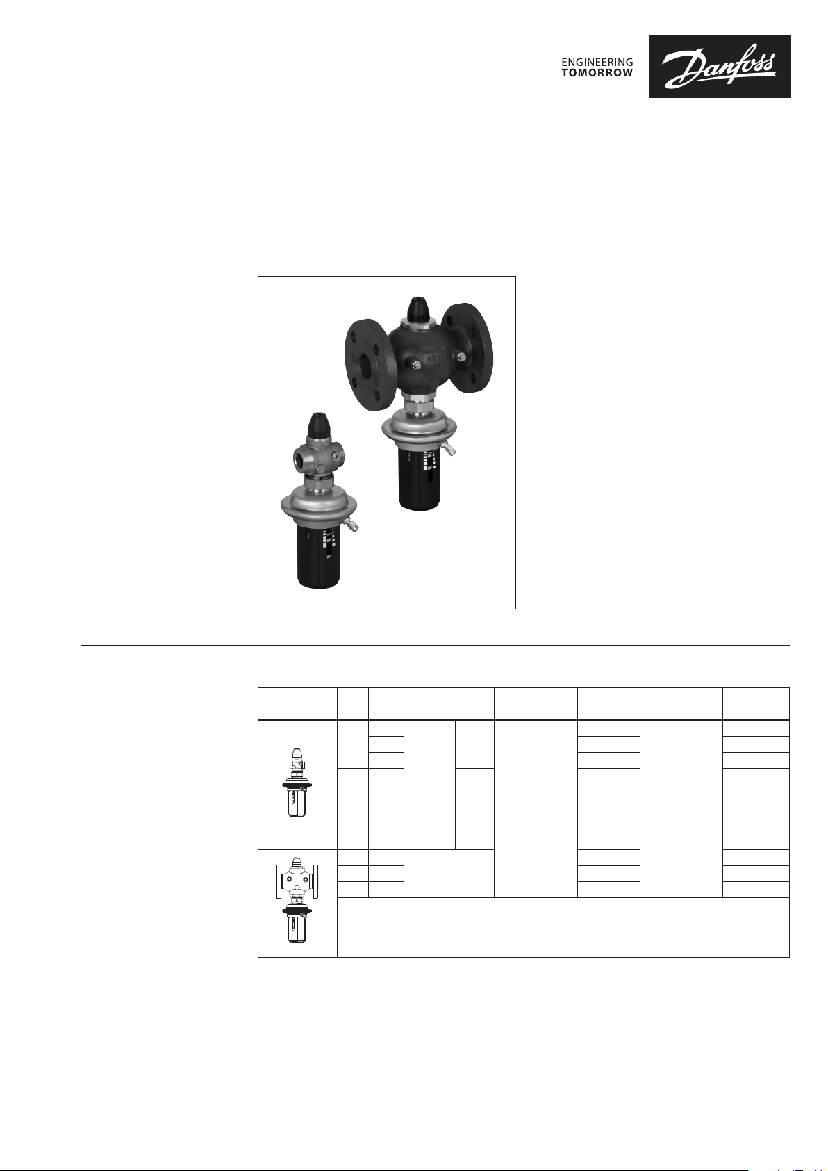
Differential pressure controller with flow limitation (PN 25)
AVPB - return mounting, adjustable setting
AVPB-F - return mounting, fixed setting
Description
Ordering
Example:
Differential pressure controller
with flow limitation; DN 15; kVS 1.6;
PN 25; setting range 0.2-1.0 bar;
t
150 °C; ext. thread
max
- 1× AVPB DN 15 controller
Code No: 003H6444
- 1× Impulse tube set AV, R ⁄
Code No: 003H6852
Option:
- 1× Weld-on tailpieces
Code No: 003H690 8
The controller will be delivered
completely assembled. External
impulse tube (AV) must be
ordered separately.
AVPB Controller
Picture
AVPB (-F) is a self-acting differential pressure
controller with flow limitation primarily for use in
district heating systems. The controller closes on
rising differential pressure or when set max. flow
is exceeded.
The controller has a control valve with adjustable
flow restrictor, an actuator with one control
diaphragm and handle for differential pressure
setting (fixed setting version is without handle).
Main data:
• DN 15-50
• kVS 1.6 -25 m3/h
• Flow range 0.03-15 m3/h
• PN 25
•
Setting range (AVPB): 0.2-1.0 bar/0.3-2.0 bar
• Fixed setting (AVPB-F): 0.5 bar
• Temperature:
Circulation water/glycolic water up to 30%:
2 … 150 °C
• Connections:
-
Ext. thread (weld-on, thread and flange tailpieces)
- Flange
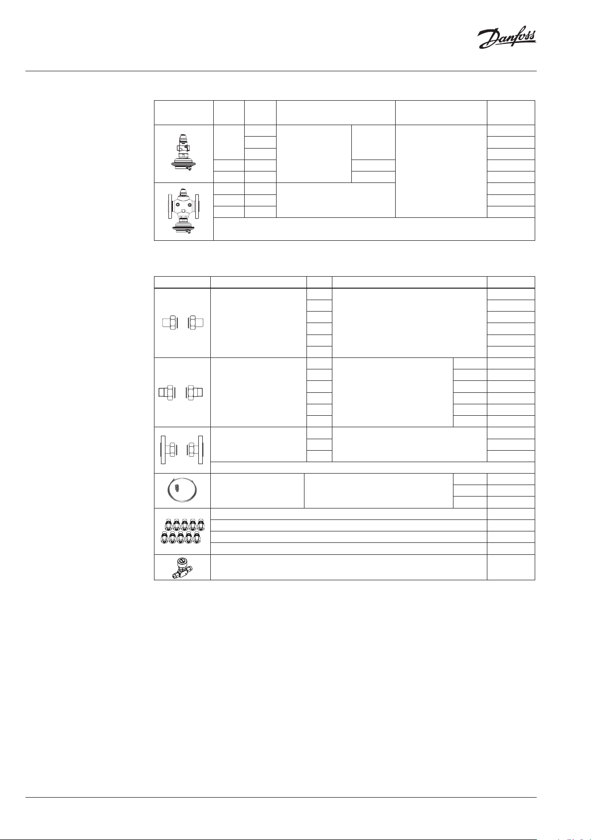
DN k
VS
(mm) (m3/h) (bar)
1.6
15
2.5 003H6445 003H6453
4.0 003H6446 003H6454
20 6.3 G 1 A 003H6447 003H6455
25 8.0 G 1¼ A 003H6448 003H6456
32 12. 5 G 1¾ A 003H6449 003H6457
40 16 G 2 A 003H6450 003H6458
50 20 G 2½ A 003H6451 003H6459
32 12. 5
40 20 003H6469 -
50 25 003H6470 -
Connection
Cylindr.
ext.
thread
acc. to
ISO 228/1
Flanges PN 25,
acc. to EN 1092-2
G ¾ A
∆p setting range
0. 2-1.0
Code No.
003H6444
003H6468 -
∆p setting range
(bar)
0.3-2.0
Code No.
003H6452
© Danfoss | 2016.09
Note: other controllers available on special request.
VD.DB.P6.02 | 1
Page 2
Data sheet Differential pressure controller with flow limitation AVPB(-F) (PN 25)
Ordering (continuous)
AVPB-F Controller
Picture
DN k
(mm)
VS
(m3/h)
1.6
15
2.5 003H6461
4.0 003H6462
ext. thread acc. to
20 6.3 G 1 A 003H6463
25 8.0 G 1¼ A 003H6464
32 12. 5
40 20 003H6475
Flanges PN 25, acc. to EN 1092-2
50 25 003H6476
Note: other controllers available on special request.
Connection
Cylindr.
ISO 228/1
G ¾ A
∆p setting range
(bar)
0.5
Accessories
Picture Type designation DN Connection Code No.
15
20 003H6909
Weld-on tailpieces
External thread tailpieces
Flange tailpieces
25 00 3H6910
32 0 03 H69 11
-
40 00 3H6912
50 0 03H6 913
15
R ½ 003H6902
20 R ¾ 003H6903
25 R 1 003H6904
Conical ex t. thread acc. to
EN 1022 6-1
32 R 1¼ 003H6905
40 R 1⁄
50 R 2
15
Flanges PN 25, acc. to EN 1092-2
20 003H 6916
25 0 03H6 917
Code No.
003H6460
003H6474
003H6908
065B2004
065B2005
003H6915
Description:
-
Impulse tube set AV
1)
10 compression f ittings for imp. tube connection to pipe, Ø6 × 1 mm R ⁄ 003H6857
1)
10 compression f ittings for imp. tube connection to pipe, Ø6 × 1 mm R ⁄ 003H6858
1)
10 compression f ittings for imp. tube connection to pipe, Ø6 × 1 mm R ⁄ 003H6859
1)
10 compression f ittings for imp. tube connection to actuator, Ø6 × 1 mm G ⁄ 0 03H6931
1x copper tube Ø6 × 1 × 150 0 mm
- 1x compression fitting1)
for imp.
Shut off valve Ø6 mm 003H0276
1)
Compression f itting consists of a nippl e, compression ring and nut.
tube connection to pipe Ø6 × 1 mm
R ⁄ 003H6852
R ⁄ 003H6853
R ⁄ 003H6854
2 | © Danfoss | 2016.09
VD.DB.P6.02
Page 3
Data sheet Differential pressure controller with flow limitation AVPB(-F) (PN 25)
Ordering (continuous)
Technical data
Service kits
k
Picture Type designation DN
VS
(m3/h)
Code No.
1.6 003H6863
Valve insert
15
20 6.3 003H6866
25
2.5 003H6864
4.0 003H6865
8.0 003H6867
32/4 0/50 12.5/16/20/25 003H6868
Type designation
Actuator with adjustable handle (AVPB)
Δp setting range
(bar)
0. 2-1.0 003H6829
0.3-2.0 003H6830
Code No.
Actuator without adjustable handle (AVPB-F) 0.5 003H6 841
Valve
Nominal diameter DN 15 20 25 32 40 50
kVS value
Range of max.
flow setting
∆pb 1) = 0.2 bar
from 0.03 0.07 0.07 0.16 0.2 0.4 0.8 0.8
to 0.86 1. 4 2.2 3.0 3.5 8.0 10 12
3)
or to
Cavitation factor z ≥ 0.6 ≥ 0. 55 ≥ 0.5
Leakage acc. to standard IEC 534 % of k
Nominal pressure PN 25
Min. differential pressure
Max. differential pressure 20 16
Medium Circulation water/glycolic water up to 30%
Medium pH Min. 7, max. 10
Medium temperature °C 2 … 150
valve External thread Ext. thread and flange
Connections
tailpieces
Materials
Valve body
thread Red bronze CuSn5ZnPb (Rg5)
flange -
Valve seat Stainless steel, mat. No. 1.4571
Valve cone Dezincing free brass CuZn36Pb2As
Sealing EPDM
Pressure relieve system
1)
∆pb - differe ntial pressure over flow rest rictor
2)
Depends o n the flow rate and valve kVS ; For Q
3)
Higher ma x flow are achieved at highe r differential pressu res over AVPB(-F) controller. In general a t p > 1-1.5 b ar
4)
Flange valve bod y
1.6 2.5 4.0 6.3 8.0 12.5 16/204)20/25
m3/h
0.9 1.6 2.4 3.5 4.5 10 12 15
VS
bar
≤ 0.02 ≤ 0.05
see remark
2)
Weld-on and external thread
Flange -
EN-GJS-400-18-LT (GGG 40.3)
Piston
= Q
-> ∆p
set
max
≥ 0.5 bar; For Q
min
< Q
->
set
p
max
min
2
Q
k
VS
Ductile iron
p
b
4)
VD.DB.P6.02
Actuator
Typ e AVPB AVPB -F
Actuator size cm
Nominal pressure PN 25
Diff. pressure setting ranges and
spring colours
Materials
Actuator
housing
Upper casing of diaphragm
Lower casing of diaphragm Dezincing free brass CuZn36Pb2As
Diaphragm EPDM
Impulse tube Copper tube Ø6 × 1 mm
bar
2
54
0. 2-1.0 0.3-2.0 0.5
yellow red (fixed setting)
Stainless steel, mat. No.1.4301
© Danfoss | 2016.09 | 3
Page 4
Data sheet Differential pressure controller with flow limitation AVPB(-F) (PN 25)
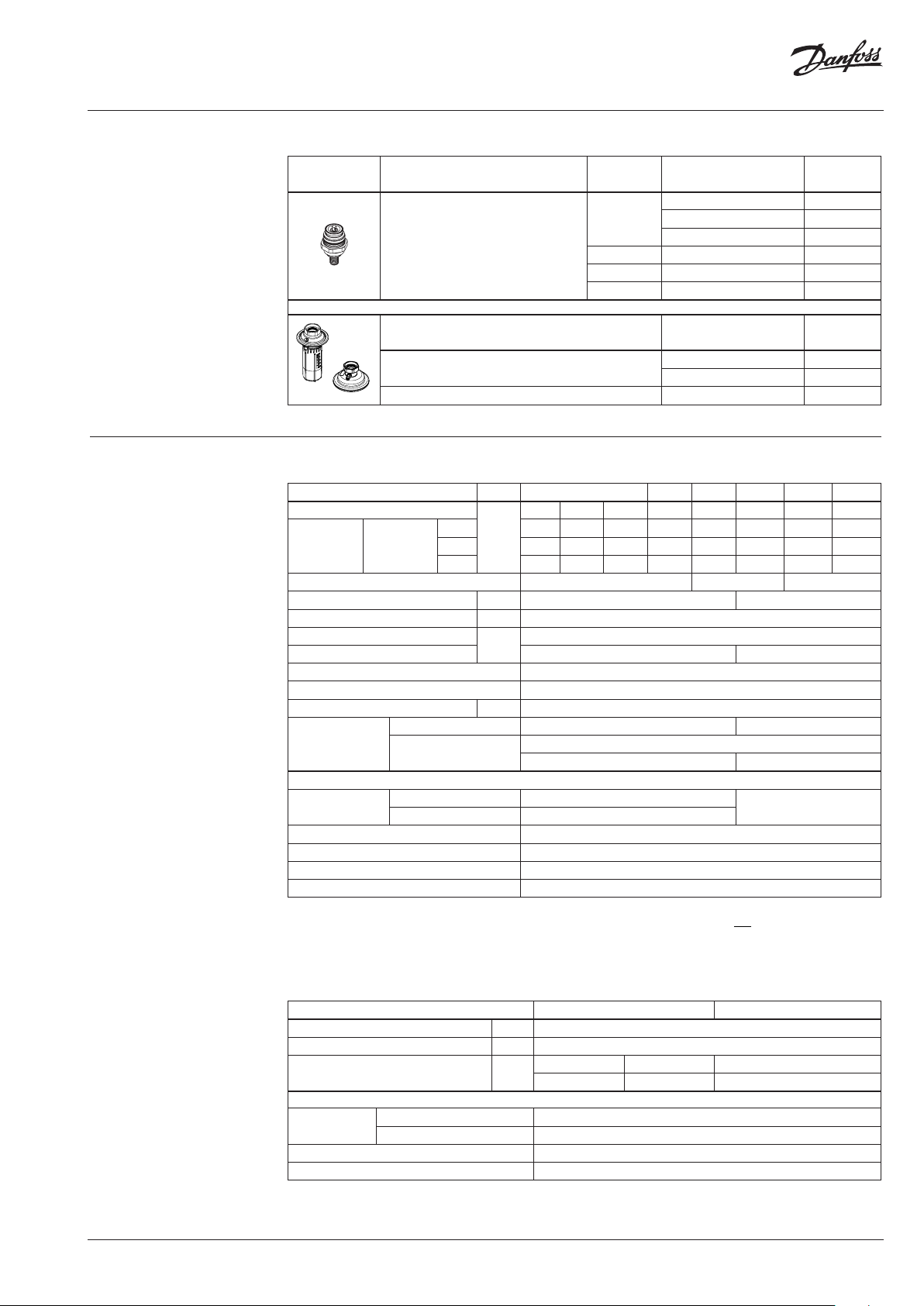
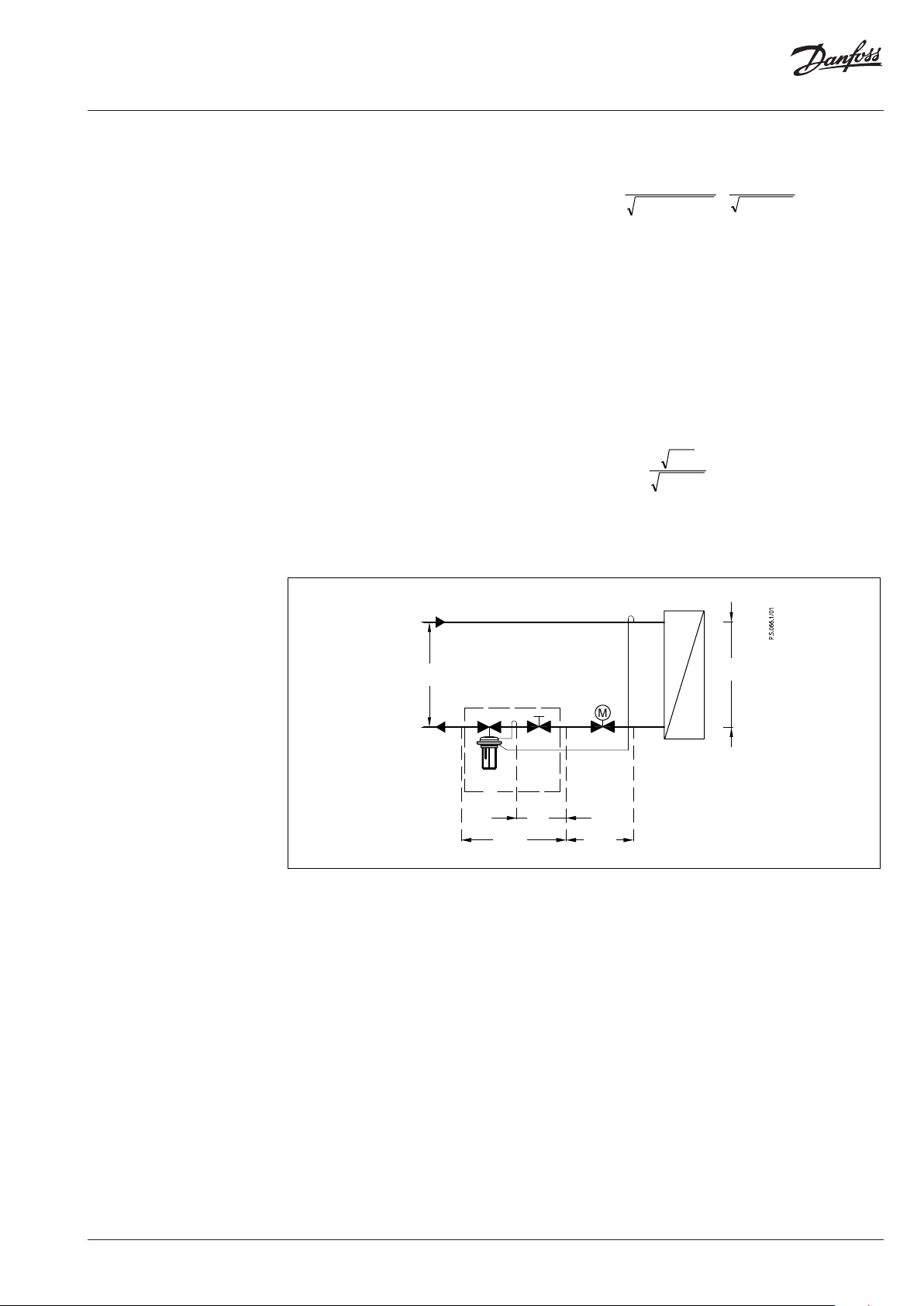
Application principles
The controller must be installed in
the return pipe only.
Direct-connected heating system Indirectly connected heating system
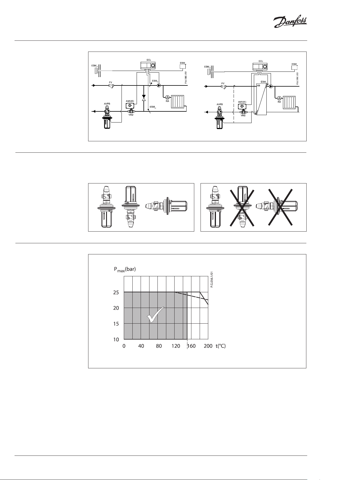
Installation positions Up to medium temperature of 100 °C the
controllers can be installed in any position.
Pressure temperature
diagram
For higher temperatures the controllers have
to be installed in horizontal pipes only, with a
pressure actuator oriented downwards.
EN-GJS-400-18-LT (GGG 40.3) PN 25
CuSn5ZnPb (Rg5) PN 25
4 | © Danfoss | 2016.09
Maximum allowed operating pressure as a func tion of medium temperature (according to EN 1092-2 and EN 1092-3).
VD.DB.P6.02
Page 5
Data sheet Differential pressure controller with flow limitation AVPB(-F) (PN 25)
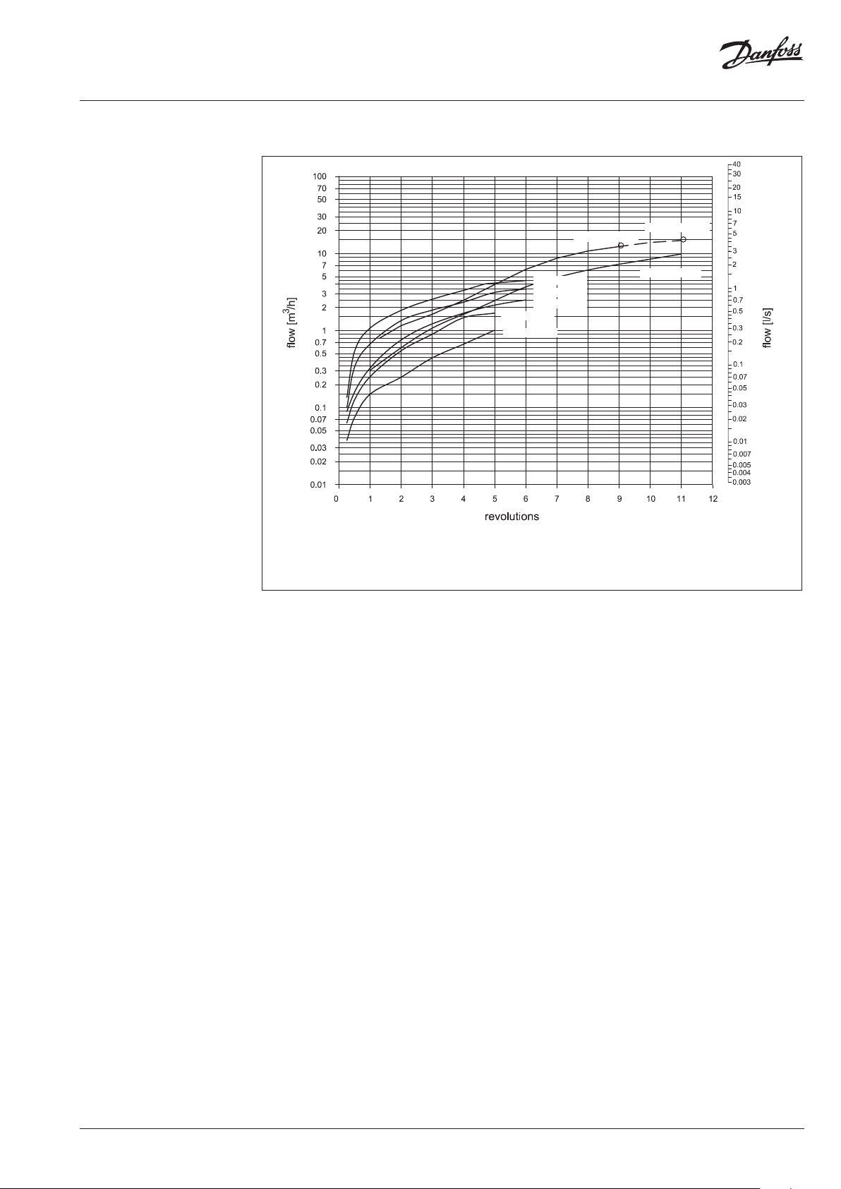
Flow diagram
Sizing and setting diagram
Relation between actual ow and number of revolutions on ow restictor. Values given are approximate.
DN 50 k
20/25
DN 32 k
VS
12. 5
VS
DN 15 k
DN 15 k
DN 25 k
DN 20 k
DN 15 k
2.5
VS
1.6
VS
8.0
VS
6.3
VS
4.0
VS
DN 40 k
VS
16/2 0
1 = 360 º
Flow can be adjusted by turning flow restrictor screw
counter-clockwise as shown in this diagram.
Water flow shown at dif ferential pressure across flow
restrictor 0.2 bar (20 kPa) and across the controller
from 0.5 bar (50 kPa) to 16/20 bar (1600/2000 kPa).
Remark:
Controllers D N 40 and DN 50 have the same cur ve up to 9
revolutions.
Note:
For max flow s etting on the controlle r diagrams from Instructi ons
should be used .
VD.DB.P6.02
© Danfoss | 2016.09 | 5
Page 6

Data sheet Differential pressure controller with flow limitation AVPB(-F) (PN 25)
Sizing
- Directly connected heating
system
Example 1
Motorised control valve (MCV) for mixing circuit
in direct-connected heating system requires
differential pressure of 0.3 bar (30 kPa) and flow
less than 1800 l/h.
Given data:
Q
= 1.8 m3/h (1800 l/h)
max
∆p
= 0.7 bar (70 kPa)
min
1)
∆p
= 0.1 bar (10 kPa)
circuit
∆p
= 0.3 bar (30 kPa) selected
MCV
2)
∆p
= 0.1 bar (10 kPa) assumption
b
Remark:
1)
∆p
corresponds to th e required pump pressure in th e
circuit
heating circui t and is not to be considered when siz ing the
AVPB.
2)
∆pb is differe ntial pressure over flow rest rictor.
The differential pressure set value is:
∆p
∆p
set value
set value
= ∆pb + ∆p
= 0.4 bar (40 kPa)
= 0.1 + 0.3
MCV
The total pressure loss across the controller is:
∆p
= ∆p
AVPB
∆p
= 0.4 bar (40 kPa)
AVPB
min
− ∆p
= 0.7 − 0.3
MCV
Q
max
Possible pipe pressure losses in tubes, shut-off
fittings, heatmeters, etc. are not included.
kv value is calculated according to formula:
Q
k
v
max
pp
bAVPB
8.1
1.04.0
kv = 3.3 m3/h
Solution:
The example selects AVPB DN 15; kVS value 4.0;
with differential pressure setting range
0.2-1.0 bar; flow setting range 0.07-2.4 m3/h.
If other differential pressure is assumed than ∆pb
= 0.1 bar, in order to maintain the kVS value, the
flow has to be adjusted using the flow restrictor
screw. The new set value (Q-setting) of the
assumed differential pressure
(∆p
= 0.2 bar) is calculated according to
b NEW
formula:
p
b
Q
setting
p
Q
max
NEW b
p
min
AVPB
p
b
p
AVPB
p
MCV
p
circuit
6 | © Danfoss | 2016.09
VD.DB.P6.02
Page 7
Data sheet Differential pressure controller with flow limitation AVPB(-F) (PN 25)
Sizing (continuous)
- Indirectly connected heating
system
Example 2
Motorised control valve (MCV) for indirectly
connected heating system requires differential
pressure of 0.3 (30 kPa) bar and flow less than
130 0 l/ h.
Given data:
Q
= 1.3 m3/h (1300 l/h)
max
∆p
= 1.0 bar (100 kPa)
min
∆p
∆p
∆pb 1) = 0.2 bar (20 kPa) assumption
Remark:
1)
∆pb is differe ntial pressure over flow rest rictor
= 0.05 bar (5 kPa)
exchanger
= 0.3 bar (30 kPa) selected
MCV
The differential pressure set value is:
∆p
∆p
∆p
= ∆pb + ∆p
set value
= 0.2 + 0.05 + 0.3
set value
= 0.55 bar (55 kPa)
set value
exchanger
+ ∆p
MCV
The total pressure loss across the controller is:
∆p
= ∆p
AVPB
∆p
= 1.0 − 0.05 − 0.3
AVPB
∆p
= 0.65 bar (65 kPa)
AVPB
min
− ∆p
exchanger
− ∆p
MCV
Possible pipe pressure losses in tubes, shut-off
fittings, heatmeters, etc. are not included.
kv value is calculated according to formula:
Q
k
v
max
pp
bAVPB
3.1
2.065.0
kv = 1.9 m3/h
Solution:
The example selects AVPB DN 15; kVS value 2.5;
with differential pressure setting range
0.2-1.0 bar; flow setting range 0.07-1.6 m3/h.
If other differential pressure is assumed than ∆pb
= 0.2 bar, in order to maintain the kVS value, the
flow has to be adjusted using the flow restrictor
screw. The new set value (Q-setting) of the
assumed differential pressure
(∆p
= 0.1 bar) is calculated according to
b NEW
formula:
p
b
Q
setting
p
Q
max
NEW b
p
Q
max
p
min
AVPB
p
b
p
AVPB
p
MCV
exchanger
VD.DB.P6.02
© Danfoss | 2016.09 | 7
Page 8

Data sheet Differential pressure controller with flow limitation AVPB(-F) (PN 25)
Design
1. Cover
2. Adjustable flow restrictor
3. Valve body
4. Valve insert
5. Pressure relieved valve cone
6. Valve stem
7. Built-in spring for flow rate
control
8. Control drain
9. Control diaphragm for diff.
pressure and flow control
10. Setting spring for diff.
pressure control
11. Handle for diff. pressure
setting, prepared for sealing
12. Union nut
13. Upper casing of diaphragm
14. Lower casing of diaphragm
15. Compression fitting for
impulse tube
16. Excess pressure safety valve
17. Actuator
AVPB
AVPB-F
Function Controller with adjustable setting is equipped
Pressure changes from the flow and return
pipe are being transferred through the impulse
tubes and/or control drain in the actuator
with excess pressure safety valve, which protects
actuator from too high differential pressure.
stem to the actuator chambers and act on
control diaphragm. Control valve closes on
rising differential pressure and opens on falling
differential pressure to maintain constant
differential pressure. Flow volume is controlled
and limited by means of the flow restrictor.
Settings
Flow setting
Flow setting is being done by the adjustment of
the flow restrictor position. The adjustment can
be performed on the basis of flow adjustment
diagram (see relevant instructions) and/or by the
means of heat meter.
Differential pressure setting
Differential pressure setting is being done by the
adjustment of the setting spring for diff. pressure
control. The adjustment can be performed on
the basis of diff. pressure adjustment diagram
(see relevant instructions) and/or pressure
indicators.
Adjustment diagram Relation between scale figures and differential pressure. Values given are approximate.
8 | © Danfoss | 2016.09
VD.DB.P6.02
Page 9
Data sheet Differential pressure controller with flow limitation AVPB(-F) (PN 25)
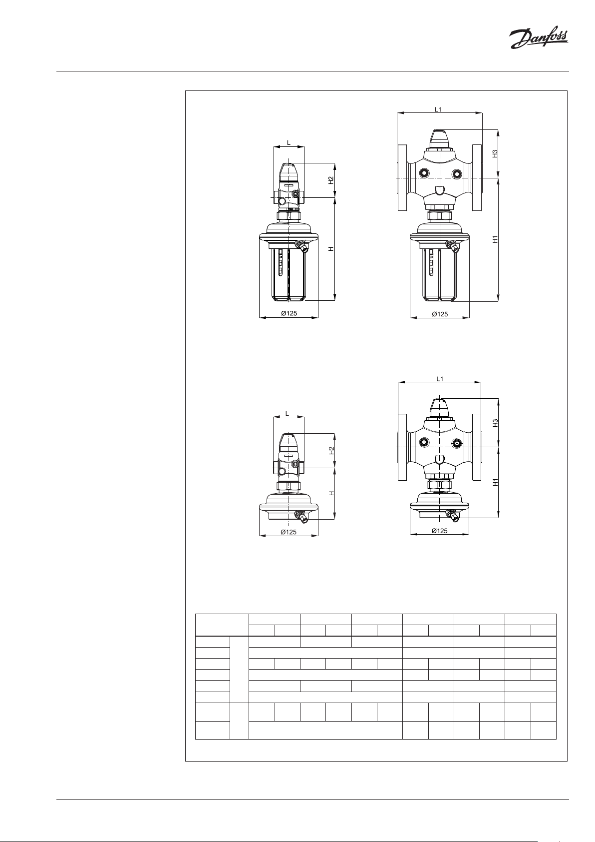
Dimensions
AVPB
DN 15-5 0
AVPB-F
DN 15-5 0
AVPB
DN 32-50
AVPB-F
DN 32-50
AVPB , AVPB-F
DN
L
L1 - 180 200 230
H 220 109 220 109 220 109 261 - 261 - 261 -
H1 - 261 150 261 150 2 61 150
H2 73 73 76 103 103 103
H3 - 103 103 103
Weight
(thread)
Weight
(flange)
Note: Other flange dimensions - see table for tailpieces.
mm
kg
15 20 25 32 40 50
AVPB AVPB -F AVPB AVPB-F AVPB AVP B-F AVPB AVPB-F AV PB AVPB -F AVPB AVPB -F
65 70 75 100 110 13 0
3.7 2.7 3.7 2.7 3.9 2.9 6.3 - 6.5 - 7.1 -
- 10.8 9.8 12 .3 11.3 14.4 13.4
VD.DB.P6.02
© Danfoss | 2016.09 | 9
Page 10

Data sheet Differential pressure controller with flow limitation AVPB(-F) (PN 25)
Dimensions (continuous)
L
3
L
2
L
1
d
2
n
d
SW
R
SW
k
SW
DN R
1)
SW d L
2)
L2L
1
mm
k d
3
2
n
15 ⁄ 32 (G ⁄A) 21 13 0 120 139 65 14 4
20 ⁄ 41 (G 1A) 26 150 131 154 75 14 4
25 1 50 (G 1⁄A) 33 16 0 145 159 85 14 4
32 1⁄ 63 (G 1¾A) 42 - 177 184 100 18 4
40 1 ⁄ 70 (G 2A) 47 - 200 204 110 18 4
50 2 82 (G 2½A) 60 - 24 4 234 125 18 4
1)
Conical ex t. thread acc. to EN 10226-1
2)
Flanges PN 25, acc. to EN 1092-2
Compression fittings
R ⁄/R ⁄/R ⁄
31 mm (R ⁄)
37 mm (R ⁄)
43 mm (R ⁄)
10 | © Danfoss | 2016.09
VD.DB.P6.02
Page 11

Data sheet Differential pressure controller with flow limitation AVPB(-F) (PN 25)
VD.DB.P6.02
© Danfoss | 2016.09 | 11
Page 12

Danf
already on order pro
All trademarks in this material are property of the respec
Data sheet Differential pressure controller with flow limitation AVPB(-F) (PN 25)
oss can accept no responsibility for possible errors in catalogues, brochures and other printed material. Danfoss reserves the right to alter its products without notice. This also applies to products
vided that such alterations can be made without subsequential changes being necessary eady agreed.
12 | © Danfoss | DHS-SRMT/SI | 2016.09
tive companies. Danfoss and the Danfoss logotype are trademarks of Danfoss A/S. All rights reserved.
VD.DB.P6.02
 Loading...