

Page 1
Data sheet
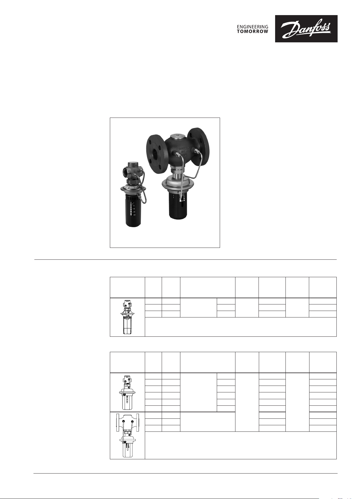
Differential pressure relief controller
AVPA(PN16 and PN 25)
Description AVPA is a self-acting differential pressure relief
controller primarily for use in district heating
systems. The controller is normally closed and
opens on rising differential pressure.
The controller has a control valve, an actuator
with one control diaphragm and handle for
differential pressure setting.
Main data:
• DN 15-50
• kVS 4.0-25 m3/h
• PN 16, 25
• Setting range:
0.05-0.5 bar / 0.2-1.0 bar / 0.3-2.0 bar
• Temperature:
- Circulation water / glycolic water up to 30 %:
2 … 150 °C
• Connections:
- External thread (weld-on, thread and flange
AVPA (PN 16) AVPA (PN 25)
tailpieces)
- Flange
Ordering
Example:
Differential pressure relief controller,
DN 15, kVS 4.0; PN 25; setting range
0.2‑1.0 bar; T
‑ 1× AVPA DN 15 controller
Code no: 003H6 602
Option:
‑ 1× Weld‑on tailpieces
Code no: 003H6908
The controller will be delivered
completely assembled, inclusive
impulse tubes between valve and
actuato r.
150 °C; ext. thread
max
AVPA PN 16 Controller
Picture
DN
(mm)
15 4.0
20 6.3 G 1 A 003H6594 003H6597
25 8.0 G 1¼ A 003H6595 003H6598
AVPA PN 25 Controller
Picture
DN
(mm)
15 4.0
20 6.3 G 1 A 003H6603 003H6606
25 8.0 G 1¼ A 003H6604 003H6607
32 12. 5 G 1¾ A 003H6599 -
40 16 G 2 A 003H6600 -
50 20 G 2½ A 003H6 601 -
32 12. 5
40 20 003H6609 003H6 612
50 25 0 03H6 610 003 H6613
k
VS
(m3/h)
k
VS
(m3/h)
Connection
Cylin dr.
ext. thread acc. to
ISO 228/1
Connection
Cylin dr.
ext. thread acc. to
ISO 228/1
Flanges PN 25,
acc. to EN 1092-2
G ¾ A
G ¾ A
∆p
setting
range
(bar)
0.05-0.5
∆p
setting
range
(bar)
0. 2-1.0
∆p
Code No.
003H6593
Code No.
003H6602
003H6608 003 H6 611
setting
range
(bar)
0. 2-1.0
∆p
setting
range
(bar)
0.3-2.0
Code No.
003H6596
Code No.
003H6605
© Danfoss | 2018.02 VD.DC.G6.02 | 1
Page 2
Data sheet AVPA (PN 16 and PN 25)
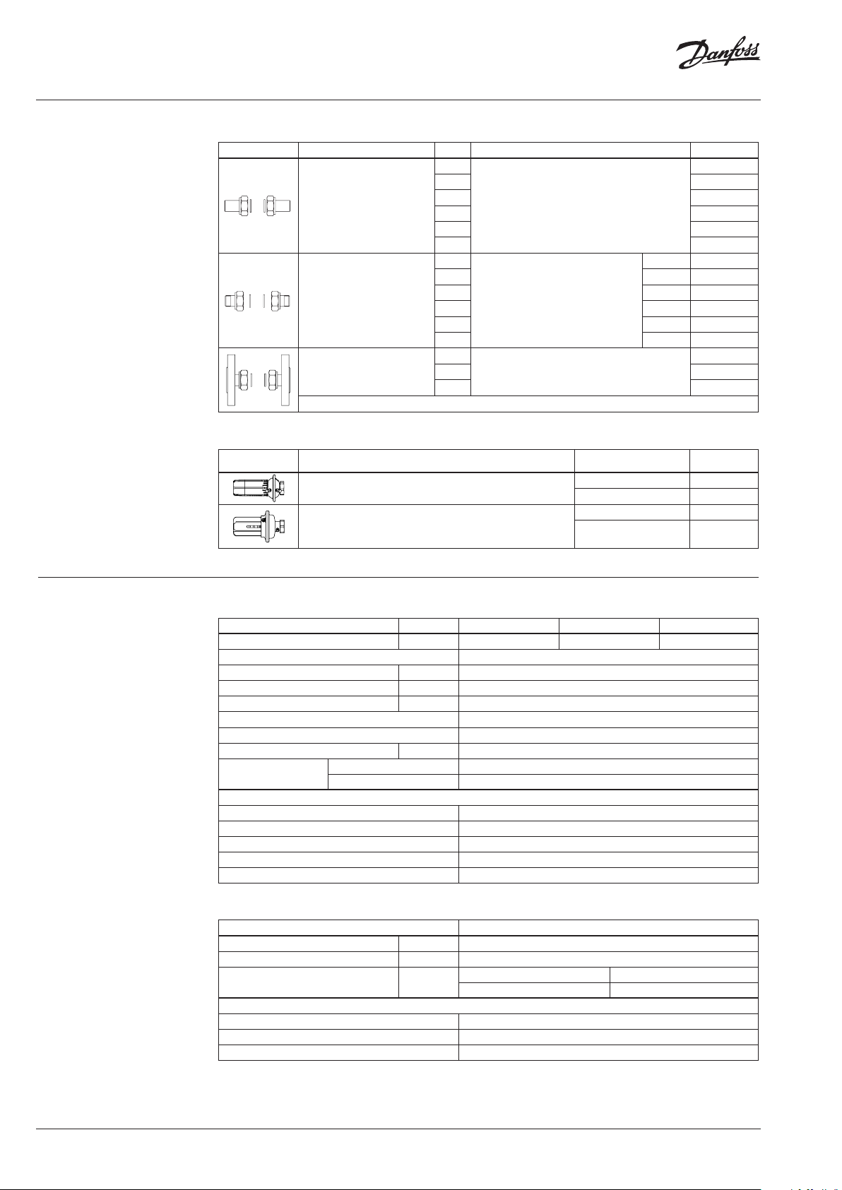
Ordering (continuous) Accessories
Picture Type designation DN Connection Code No.
Weld-on tailpieces
External thread tailpieces
Flange tailpieces
15
003H6908
20 003H6909
25 00 3H6910
32 0 03 H69 11
-
40 00 3H6912
50 0 03H6 913
15
R ½” 003H6902
20 R ¾” 003H6903
25 R 1” 003H6904
Conical ex t. thread acc. to
EN 10226 -1
32 R 1¼” 003H6905
40 R 1½ 065B2004
50 R 2 065B2005
15
Flanges PN 25, acc. to EN 1092-2
20 003H 6916
003H6915
25 0 03H6 917
Technical data
Service kits
Picture Type designation
Actuator with adjustable handle PN 16
Actuator with adjustable handle PN 25
Δp setting range
(bar)
0.05-0.5 003H6823
0. 2-1.0 003H6824
0. 2-1.0 003H6834
0.3-2.0 003H6835
Valve (for AVPA PN 16)
Nominal diameter DN 15 20 25
k
value m3/h 4.0 6.3 8.0
VS
Cavitation factor z ≥ 0.6
Leakage acc. to standard IEC 534 % of k
Nominal pressure PN 25
Max. dierential pressure bar 12
Medium Circulation water / glycolic water up to 30%
Medium pH Min. 7, max. 10
Medium temperature
Connections
Materials
Valve body Red bronze CuSn5ZnPb (Rg5)
Valve seat Stainless steel, mat. No. 1.4571
Valve cone Dezincing free brass CuZn36Pb2As
Sealing EPDM
Pressure relieve system
valve External thread
tailpieces Weld-on, external thread and ange
VS
°
C 2 … 150
≤ 0.2
Piston
Code No.
Actuator (for AVPA PN 16)
Typ e AVPA P N 16
Actuator size
Nominal pressure
Di. pressure setting ranges and
spring colours
Materials
Actuator housing Zinc plated, DIN 1624, No. 1.0338
Diaphragm EPDM
Impulse tube Copper tube Ø6 × 1 mm
cm
PN
bar
2
0.05-0.5 0 .2-1.0
grey black
39
16
2 | VD.DC.G6.02 © Danfoss | 2018.02
Page 3
Data sheet AVPA (PN 16 and PN 25)
Technical data (continuous)
Valve (for AVPA PN 25)
Nominal diameter DN 15 20 25 32 40 50
k
value m3/h 4.0 6.3 8.0 12. 5 16/20 1)20/25
VS
Cavitation factor z ≥ 0.6 ≥ 0.55 ≥ 0.5
Leakage acc. to standard IEC 534 % of k
Nominal pressure PN 25
Max. dierential pressure bar 20 16
Medium Circulation water / glycolic water up to 30 %
Medium pH Min. 7, max. 10
Medium temperature
valve Thread Thread and ange
Connections
Materials
Valve body
Valve seat Stainless steel, mat. No. 1.4571
Valve cone Dezincing free brass CuZn36Pb2As
Sealing EPDM
Pressure relieve system
1)
Flange valve bod y
tailpieces
thread
ange -
VS
°
C 2 …150
Red bronze CuSn5ZnPb (Rg5) Ductile iron
≤ 0.02 ≤ 0.05
Weld-on and external thread
Flange -
EN-GJS-400 -18-LT
(GGG 40.3)
Piston
Actuator (for AVPA PN 25)
Typ e AVPA PN 25
Actuator size cm
Nominal pressure PN 25
Diff. pressure setting ranges and
spring colours
Materials
Actuator housing
Diaphragm EPDM
Impulse tube Copper tube Ø6 × 1 mm
Upper casing of diaphragm
Lower casing of diaphragm
bar
2
0. 2-1.0 0 .3-2. 0
yellow red
Stainless steel, mat. No.1.4301
Dezincing free brass CuZn36Pb2As
54
1)
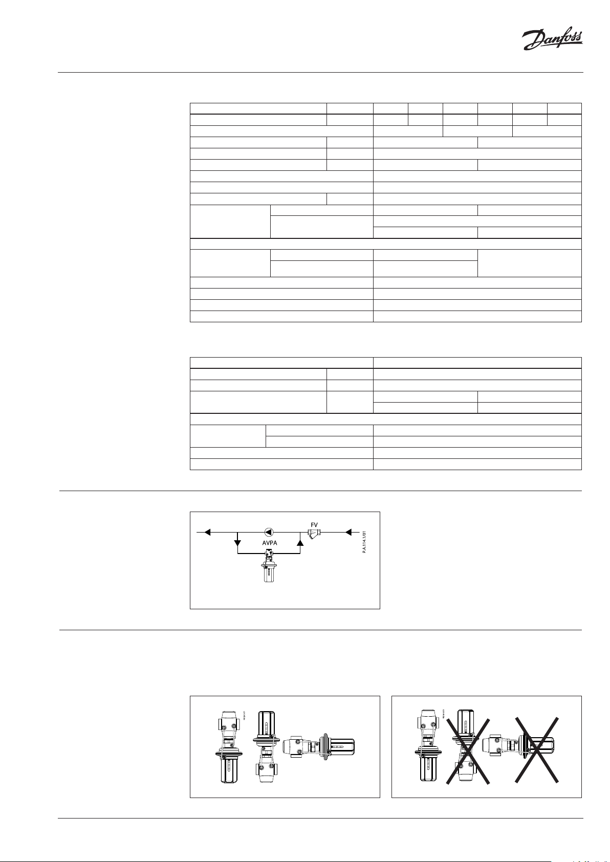
Application principle
Differential pressure control for a pump in bypass
Installation positions Up to medium temperature of 100 °C the
controllers can be installed in any position.
For higher temperatures the controllers have
to be installed in horizontal pipes only, with a
pressure actuator oriented downwards.
VD.DC.G6.02 | 3© Danfoss | 2018.02
Page 4

Data sheet AVPA (PN 16 and PN 25)
Pressure temperature
diagram
Maximum allowed operating pressure as a function of medium temperature (according to EN 1092‑2 and EN 1092‑3).
③ EN‑GJS‑ 400‑18‑LT (GGG 40.3) PN 25
② CuSn5ZnPb (Rg5) PN 25
① CuSn5ZnPb (Rg5) PN 16
Sizing
Design
1. Valve body
2. Valve insert
3. Pressure relieved valve cone
4. Valve stem
5. Control diaphragm for diff.
pressure control
6. Setting spring for diff.
pressure control
7. Handle for diff. pressure
setting, prepared for sealing
8. Union nut
9. Upper casing of diaphragm
10. Lower casing of diaphragm
11. Impulse tube
12. Compression fitting for
impulse tube
13. Act uator
Given data:
Q
= 4.5 m3/h
max
∆p
= 1.4 bar
AVPA
Nominal pressure PN 25
kv value is calculated according to formula:
AVPA
4.5
1.4
Q
k
max
v
p
kv = 3.8 m3/h
Solution:
The example selects AVPA PN 25 DN 15,
kVS value 4.0 with differential pressure setting
range 0.3-2.0 bar.
4 | VD.DC.G6.02 © Danfoss | 2018.02
Page 5

Data sheet AVPA (PN 16 and PN 25)
Function The pressures in front and behind of the control
valve are being transferred through the impulse
tubes to the actuator chambers and act on
control diaphragm. Control valve is normally
closed. It opens on rising differential pressure
and closes on falling differential pressure to
maintain constant differential pressure.
Controller is equipped with excess pressure
safety valve, which protects control diaphragm
for diff. pressure control from too high
differential pressure.
Settings Differential pressure setting
Differential pressure setting is being done by the
adjustment of the setting spring for differential
pressure control. The adjustment can be done by
means of spring for differential pressure setting
and/or pressure indicators
Adjustment Relation between scale figures and differential pressure. Values given are approximate.
VD.DC.G6.02 | 5© Danfoss | 2018.02
Page 6

Data sheet AVPA (PN 16 and PN 25)
Dimensions
L
L
1
L
Ø106
2
H
4
H
Ø106
L
2
H
H
Ø125
2
H
H
Ø125
PN 16 PN 25 PN 25 PN 25
DN 15 ‑ 25 DN 15 ‑ 25 DN 32 ‑ 50 DN 32 ‑ 50
L L
DN
15 65 - 233 - 34 - 232 1. 8 3. 5 -
20 70 - 233 - 34 - 232 1.8 5.5 -
25 72 - 233 - 37 - 232 2.0 3.7 -
32 100 180 275 275 62 70 - - 5.8 10.4
40 110 200 275 275 62 75 - - 5.9 11.9
50 130 230 275 275 62 82 - - 6.6 13. 9
Note: other flange dimensions ‑ see table for tailpieces
H H
1
H
H
1
2
H
3
4
mm PN 16
Weight (kg)
PN 25
thread flange
3
H
1
H
d
L
L
3
d
R
SW
L
2
SW
1
SW
DN R
1)
SW d L
2)
L2L
1
k d
3
2
mm
2
n
k
45°
n
15 ⁄ 32 (G ⁄A) 21 130 120 139 65 14 4
20 ⁄ 41 (G 1A) 26 150 131 154 75 14 4
25 1 50 (G 1⁄A) 33 160 145 15 9 85 14 4
32 1⁄ 63 (G 1¾A) 42 - 177 184 100 18 4
40 1 ⁄ 70 (G 2A) 47 - 200 204 110 18 4
50 2 82 (G 2½A) 60 - 244 234 125 18 4
1)
Conical ex t. thread acc. to EN 10226‑1
2)
Flanges PN 25, acc. to EN 1092‑2
6 | VD.DC.G6.02 © Danfoss | 2018.02
Page 7

Data sheet AVPA (PN 16 and PN 25)
VD.DC.G6.02 | 7© Danfoss | 2018.02
Page 8

Danf
already on order pro
All trademarks in this material are property of the respec
Data sheet AVPA (PN 16 and PN 25)
oss can accept no responsibility for possible errors in catalogues, brochures and other printed material. Danfoss reserves the right to alter its products without notice. This also applies to products
vided that such alterations can be made without subsequential changes being necessary eady agreed.
tive companies. Danfoss and the Danfoss logotype are trademarks of Danfoss A/S. All rights reserved.
© Danfoss | DHS-SRMT/SI | 2018.028 | VD.DC.G6.02
 Loading...