

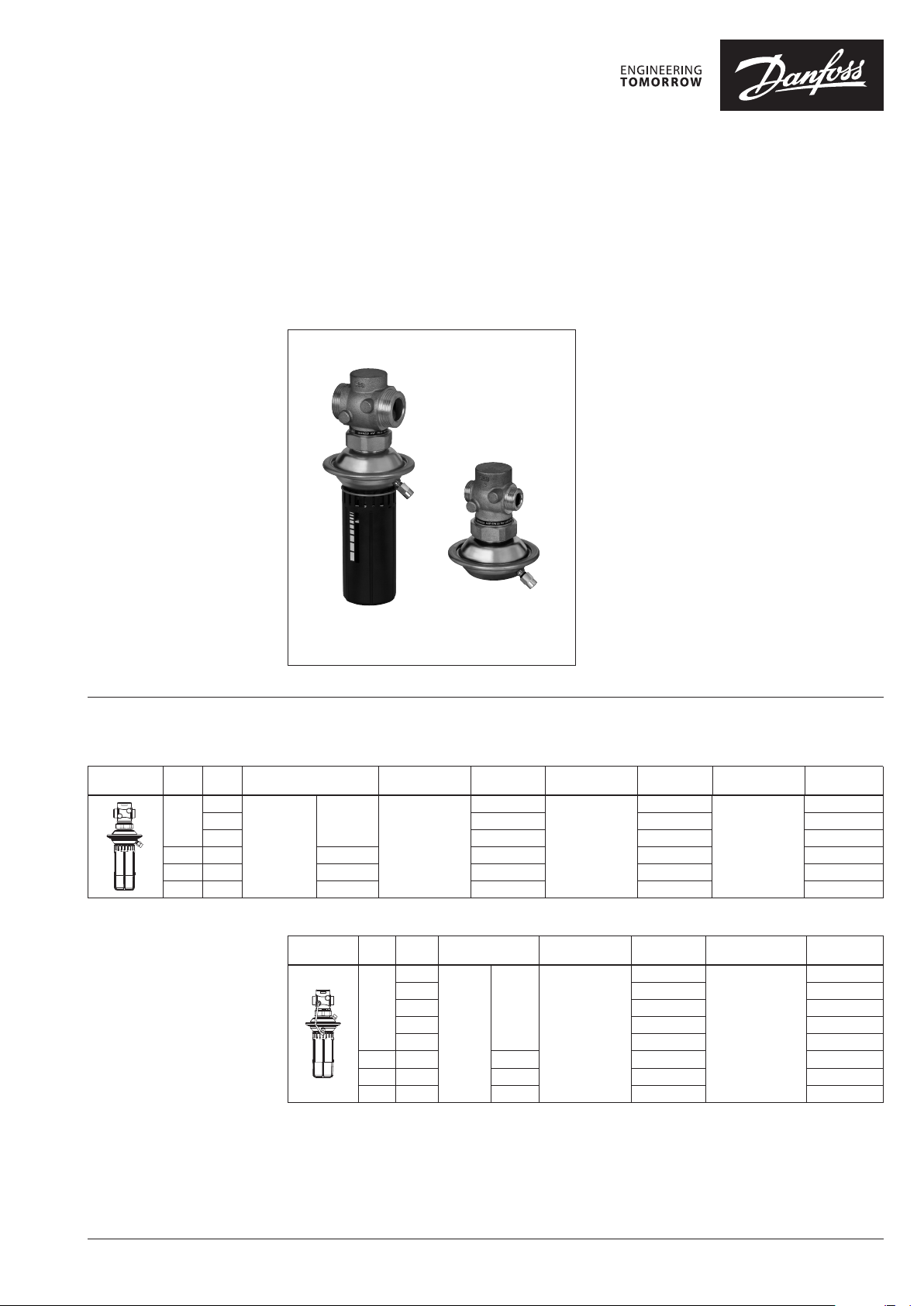
Data sheet
Differential pressure controller (PN 16)
AVP - return and flow mounting, adjustable setting
AVP-F - return mounting, fixed setting
Description
Ordering
AVP Controller (return mounting)
DN
k
Picture
(mm)
VS
(m3/h)
1.6
15
2.5 003H6201 003H6207 00 3H6213
Cylin dr.
4.0 003H6202 003H6208 00 3H6214
ext. thread
20 6.3 G 1 A 003H6203 003H6209 003 H6215
25 8.0 G 1¼ A 003H6204 003H6210 0 03H6216
32 10 G 1¾ A 003H6205 0 03 H62 11 0 03H 6217
acc. to
ISO 228/1
Connection
G ¾ A
AVP
∆p setting range
0.05-0.5
(bar)
AVP-F
Code No.
003H6200
AVP(-F) is a self-acting differential pressure
controller primarily for use in district heating
systems. The controller closes on rising
differential pressure.
The controller has a control valve, an actuator
with one control diaphragm and handle for
differential pressure setting (fixed setting version
is without handle).
Main data:
• DN 15-32
• kVS 0.4 -10 m3/h
• PN 16
• Setting range (AVP):
0.05-0.5 bar / 0.2-1.0 bar / 0.8-1.6 bar
• Fixed setting (AVP-F): 0.2 bar / 0.3 bar / 0.5 bar
• Temperature:
- Circulation water / glycolic water up to 30%:
2 … 150 °C
• Connections:
- Ext. thread (weld-on, thread and flange
tailpieces)
∆p setting range
(bar)
0. 2-1.0
Code No.
003H6206
∆p setting range
(bar)
0. 8-1.6
Code No.
00 3H6212
Example 1:
Differential pressure controller;
return mounting; DN 15; kVS 1.6;
PN16; setting range 0.2-1.0 bar;
T
150 °C; ext. thread;
max
- 1× AVP DN 15 controller
Code No: 003H6206
- 1× Impulse tube set AV, R ⁄
Code No: 003H6 852
Option:
- 1× Weld-on tailpieces
Code No: 003H6908
The controller will be delivered
AVP Controller (flow mounting)
DN
k
Picture
1)
This version of controller ca n be mounted in return or in f low pipe. When orderi ng 2 impulse tube sets AV (instead o f 1) should be
ordered (see ordering example 2).
(mm)
VS
(m3/h)
0.4
1.0 -
15
1.6 003H6238 003H6244
2.5 003H6239 003H6245
4.0 003H6240 003H624 6
20 6.3 G 1 A 003 H6241 003H6247
25 8.0 G 1¼ A 003H6242 003H6248
32 10 G 1¾ A 003H6243 003H6249
Connection
Cylin dr.
ext.
thread
acc. to
ISO 228/1
G ¾ A
∆p setting range
(bar)
0.05-0.5
Code No.
-
∆p setting range
(bar)
0. 2-1.0
Code No.
003H6947
003H694 8
1)
1)
completely assembled, inclusive
impulse tube between valve and
actuator. External impulse tube (AV)
must be ordered separately.
© Danfoss | 2019.02 VD.DB.G7.02 | 1
Data sheet Differential pressure controller (PN 16) AVP, AVP-F
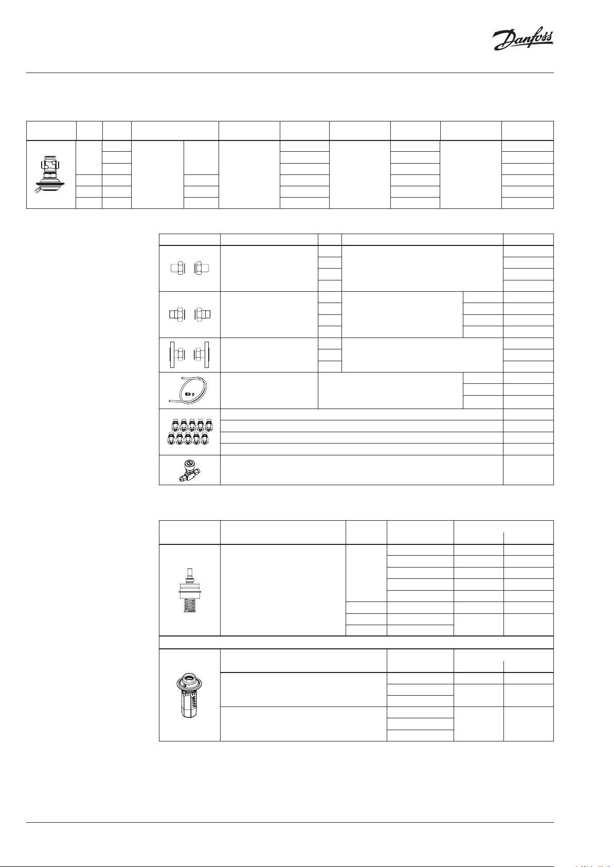
Ordering (continuous)
AVP- F Controller (return mounting)
DN
Picture
k
(mm)
VS
(m3/h)
1.6
15
2.5 003 H6219 003H6225 003H6231
4.0 003H6220 003H6226 003H6232
20 6.3 G 1 A 003H6221 0 03H6227 003H6233
25 8.0 G 1¼ A 003H6222 003H6228 003H6234
32 10 G 1¾ A 003H6223 003H6229 003H6235
Connection
Cylin dr.
ext. thread
acc. to
ISO 228/1
G ¾ A
∆p setting range
(bar)
0.2
Code No.
003 H6218
∆p setting range
(bar)
0.3
Code No.
003H6224
∆p setting range
(bar)
0.5
Code No.
003H6230
Example 2:
Differential pressure controller; flow
mounting; DN 15; kVS 0.4; PN 16;
setting range 0.2-1.0 bar; T
ext. thread;
150 °C;
max
- 1× AVP DN 15 controller
Code No: 003H6 947
- 1× Impulse tube set AV, R ⁄
Code No: 003H6 852
Option:
- 1× Weld-on tailpieces
Code No: 003H6908
The controller will be delivered
completely assembled, inclusive
impulse tube between valve and
actuator. External impulse tube (AV)
must be ordered separately.
Accessories
Picture Type designation DN Connection Code No.
15
Weld-on tailpieces
External thread tailpieces
Flange tailpieces
Impulse tube set AV
1)
10 compression fittings for imp. tube connection to pipe, Ø 6 × 1 mm R ⁄ 003H6857
1)
10 compression fittings for imp. tube connection to pipe, Ø 6 × 1 mm R ⁄ 003H6858
1)
10 compression fittings for imp. tube connection to pipe, Ø 6 × 1 mm R ½ 003H6859
1)
10 compression fittings for imp. tube connection to actuator, Ø 6 × 1 mm G ⁄ 003 H6931
Shut off valve Ø 6 mm 003H0276
1)
Compression f itting consists of a nippl e, compression ring and nut.
20 003H6909
25 00 3H6910
32 0 03 H69 11
15
20 R ¾ 003H6903
25 R 1 003H6904
32 R 1¼ 003H6905
15
20 003H 6916
25 0 03H6 917
Description:
- 1× copper tube Ø 6 × 1 × 1500 mm
- 1× compression fitting 1) for imp. tube
connection to pipe Ø 6 × 1 mm
Conical ex t. thread acc. to
EN 10226 -1
Flanges PN 25, acc. to EN 1092-2
-
R ½ 003H6902
R ⁄ 003H6852
R ⁄ 003H 6853
R ½ 003H6854
Service kits
Picture Type designation DN
15
Valve insert
20 6.3 003H6866 003H 6874
25 8.0
32 10
k
VS
(m3/h)
0.4 - 003H6869
1.0 - 003H6870
1.6 003H6863 003H6871
2.5 003H6864 003H6872
4.0 003H6865 003H6873
AVP(-F) return AVP(-F) flow
Code No.
003H6867 003H 6875
003H6908
003H6915
Type designation
Actuator with adjustable handle (AVP)
Actuator without adjustable handle (AVP-F)
Δp setting range
(bar)
0.05-0.5 003H6821 003H6823
0. 2-1.0
0. 8-1.6
0.2
0.5
AVP(-F) return AVP(-F) flow
Code No.
003H6822 003H6824
003H6825 -0.3
2 | VD.DB.G7.02 © Danfoss | 2019.02
Data sheet Differential pressure controller (PN 16) AVP, AVP-F
Technical data
Valve
Nominal diameter DN 15 20 25 32
k
value m3/h 0.4 1. 0 1.6 2.5 4.0 6.3 8.0 10
VS
Cavitation factor z ≥ 0.6 ≥ 0.55
Leakage acc. to standard IEC 534 % of k
Nominal pressure PN 25
Max. differential pressure bar 12
Medium Circulation water / glycolic water up to 30%
Medium pH Min. 7, Max. 10
Medium temperature °C 2…15 0
valve Extternal thread
Connections
Materials
Valve body Red bronze CuSn5ZnPb (Rg5)
Valve seat Stainless steel, mat. No. 1.4571
Valve cone Dezincing free brass CuZn36Pb2As
Sealing EPDM
Pressure relieve system Piston
tailpieces
VS
≤ 0.02 ≤ 0.05
Weld-on and external thread
Flange -
Actuator
Typ e AVP AVP- F
Actuator size cm
Nominal pressure PN 16
Diff. pressure setting ranges and
spring colours
Materials
Actuator housing Zinc plated, DIN 1624, No. 1.0338
Diaphragm EPDM
Impulse tube Copper tube Ø 6 x 1 mm
2
0.05-0.5 0.2-1.0 0.8 -1.6 0.2 0.3 0.5
bar
grey black (fixed setting)
39
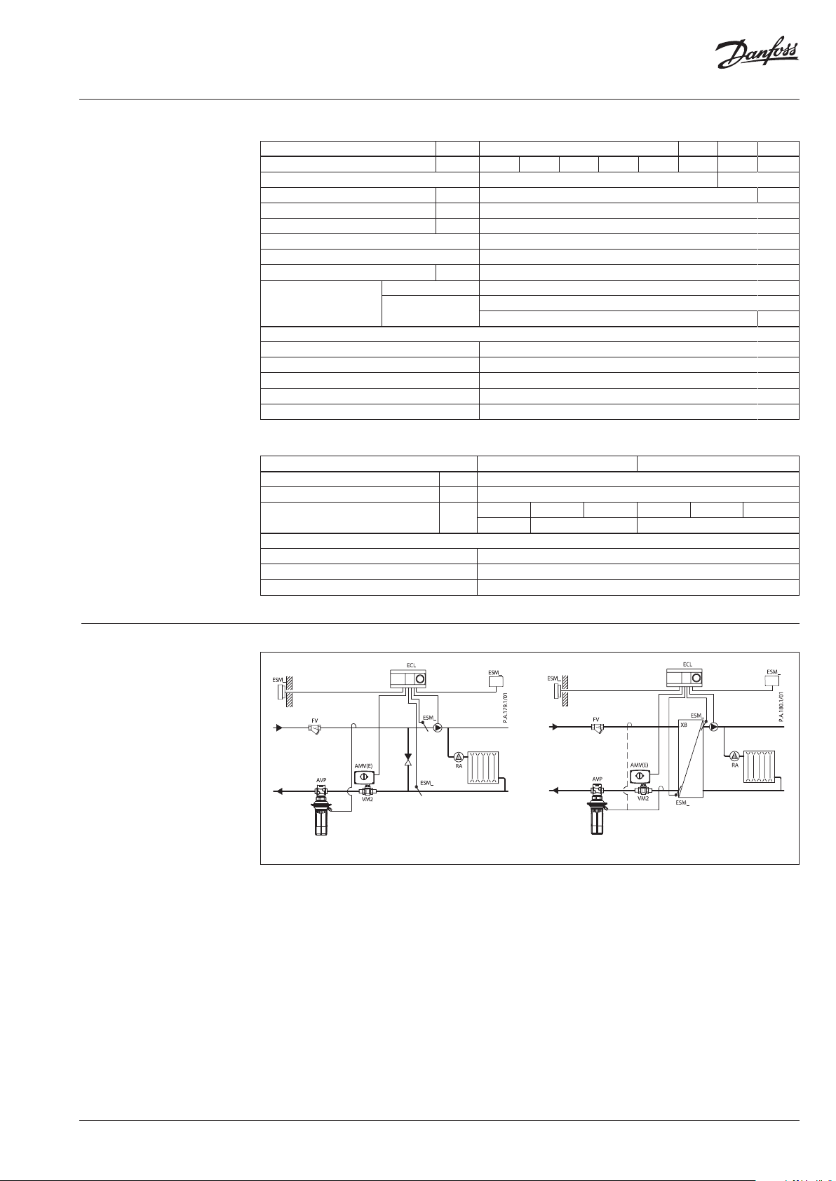
Application principles
- Return mounting
Direct-connected heating system Indirectly connected heating system
VD.DB.G7.02 | 3© Danfoss | 2019.02
Data sheet Differential pressure controller (PN 16) AVP, AVP-F
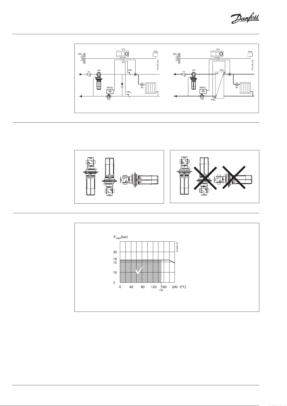
Application principles
- Flow mounting
Direct-connected heating system Indirectly connected heating system
Installation positions Up to medium temperature of 100 °C the
controllers can be installed in any position.
Pressure temperature
diagram
For higher temperatures the controllers have
to be installed in horizontal pipes only, with a
pressure actuator oriented downwards.
CuSn5ZnPb (Rg5) PN 16
Maximum allowed operating pressure as a function of medium temperature (according to EN 1092-3).
4 | VD.DB.G7.02 © Danfoss | 2019.02

Data sheet Differential pressure controller (PN 16) AVP, AVP-F
Sizing
- Directly connected heating
system
Example 1
Motorised control valve (MCV) for mixing circuit
in direct-connected heating system requires
differential pressure of 0.2 bar (20 kPa).
Given data:
Q
= 1.3 m3/h (1300 l/h)
max
∆p
= 0.7 bar (70 kPa)
min
*∆p
= 0.1 bar (10 kPa)
circuit
∆p
= 0.2 bar (20 kPa) selected
MCV
*Remark
p
corresponds to the required pump pressure in the
circuit
heating circuit and is not to be considered when sizing the AVP
The dierential pressure set value is:
∆p
= ∆p
∆p
set value
set value
MCV
= 0.2 bar (20 kPa)
The total pressure loss across the controller is:
∆p
= ∆p
AVP
∆p
= 0.5 bar (50 kPa)
AVP
min
− ∆p
= 0.7 − 0.2
MCV
Possible pipe pressure losses in tubes, shut-o
ttings, heatmeters, etc. are not included.
kv value is calculated according to formula:
Q
k
max
v
Δp
1.3
AVP
0.5
kv = 1.8 m3/h
or read from the sizing diagram, page 7, by
taking a line from Q-scale (1.3 m3/h) through ∆pvscale (0.5 bar) to intersect kv-scale at 1.8 m3/h.
Solution:
The example selects AVP DN 15, kVS value 2.5,
with dierential pressure setting range
0.05-0.5 bar.
The P-band (Xp) can also be read from the sizing
diagram. Take a horizontal line from the kv-scale
(1.8 m3/h) to the right to intersect the Xp-scale
(0.04 bar). At a set value of 0.2 bar and a Xp of
0.04 bar the AVP controller controls between
0.2 bar with open motorised control valve and
0.2 + 0.04 = 0.24 bar at almost closed motorised
control valve (i.e. total pressure loss across the
motorised control valve).
VD.DB.G7.02 | 5© Danfoss | 2019.02

Data sheet Differential pressure controller (PN 16) AVP, AVP-F
Sizing (continuous)
- Indirectly connected heating
system
Example 2
Motorised control valve (MCV) for indirectly
connected heating system requires dierential
pressure of 0.3 (30 kPa) bar.
Given data:
Q
= 0.8 m3/h (800 l/h)
max
∆p
= 0.8 bar (80 kPa)
min
∆p
∆p
= 0.05 bar (5 kPa)
exchanger
= 0.3 bar (30 kPa) selected
MCV
The dierential pressure set value is:
∆p
∆p
= ∆p
set value
set value
exchanger
= 0.35 bar (35 kPa)
+ ∆p
= 0.05 + 0.3
MCV
The total pressure loss across the controller is:
∆p
= ∆p
AVP
= 0.8 − 0.05 − 0.3
∆p
= 0.45 bar (45 kPa)
AVP
min
− ∆p
exchanger
− ∆p
MCV
Possible pipe pressure losses in tubes, shut-o
ttings, heatmeters, etc. are not included.
kv value is calculated according to formula:
Q
k
max
v
Δp
0.8
AVP
0.45
kv = 1.2 m3/h
or read from the sizing diagram, page 7, by
taking a line from Q-scale (0.8 m3/h) through ∆pvscale (0.45 bar) to intersect kv-scale at 1.2 m3/h.
Solution:
The example selects AVP DN 15, kVS value 1.6,
with dierential pressure setting range
0.05-0.5 bar.
The P-band (XP) can also be read from the sizing
diagram. Take a horizontal line from the kv-scale
(1.2 m3/h) to the right to intersect the XP-scale
(0.04 bar). At a set value of 0.35 bar and a XP of
0.04 bar the AVP controller controls between
0.35 bar with open motorised control valve and
0.35 + 0.04 = 0.39 bar at almost closed motorised
control valve (i.e. total pressure loss across the
motorised control valve).
6 | VD.DB.G7.02 © Danfoss | 2019.02

Data sheet Differential pressure controller (PN 16) AVP, AVP-F
Sizing (continuous)
Select suitable controller size. Xp should not exceed 50% of the controller differential pressure setting.
VD.DB.G7.02 | 7© Danfoss | 2019.02

Data sheet Differential pressure controller (PN 16) AVP, AVP-F
Design
1. Valve body
2. Valve insert
3. Pressure relieved valve cone
4. Valve stem
5. Control drain
6. Actuator
7. Control diaphragm for diff.
pressure control
8. Setting spring for diff.
pressure control
9. Handle for diff. pressure
setting, prepared for sealing
10. Union nut
11. Compression fitting for
impulse tube
12 . Excess pressure safety valve
AVP
AVP- F
Function Pressure changes from flow and return pipes are
being transferred through the impulse tubes
and/or control drain in the actuator stem to
the actuator chambers and act on control
diaphragm for diff. pressure control. The diff.
pressure is controlled by means of setting spring
for diff. pressure control. Control valve closes on
rising differential pressure and opens on falling
differential pressure to maintain constant
differential pressure.
Settings Differential pressure setting
Differential pressure setting (valid for AVP
controller only) is being done by the adjustment
of the setting spring for diff. pressure control.
The adjustment can be done by means of
handle for diff. pressure setting and/or pressure
indicators.
Adjustment diagram
Relation between scale figures and differential pressure. Values given are approximate.
Controller is equipped with excess pressure
safety valve, which protects control diaphragm
for diff. pressure control from too high
differential pressure.
8 | VD.DB.G7.02 © Danfoss | 2019.02

Data sheet Differential pressure controller (PN 16) AVP, AVP-F
Dimensions
AVP (ow, return)
DN
d
AVP- F (return)
L H H2
mm
15 65 232 34 1.7
20 70 232 34 1. 8
25 75 232 38 1.9
32 100 232 38 2.2
L
3
SW
1)
DN R
15 ⁄ 32 (G ⁄A) 21 130 120 139 65 14 4
20 ⁄ 41 (G 1A) 26 150 131 154 75 14 4
25 1 50 (G 1⁄A) 33 160 145 159 85 14 4
32 1⁄ 63 (G 1 ⁄A) 42 - 177 184 - - -
1)
Conical ex t. thread acc. to EN 10226-1
2)
Flanges PN 25, acc. to EN 1092-2
Weight
(kg)
L
2
R
SW
SW d L1 2)L2L
mm
DN
15 65 97 34 1.3
20 70 97 34 1. 4
25 75 97 38 1.5
32 100 97 38 1. 8
L
1
3
L H H2
mm
n
SW
k d
2
n
Weight
(kg)
d
2
45°
k
R ⁄ / R ⁄ / R ⁄
Compression ttings
31 mm (R ⁄)
37 mm (R ⁄)
43 mm (R ⁄)
VD.DB.G7.02 | 9© Danfoss | 2019.02

Data sheet Differential pressure controller (PN 16) AVP, AVP-F
10 | VD.DB.G7.02 © Danfoss | 2019.02

Data sheet Differential pressure controller (PN 16) AVP, AVP-F
VD.DB.G7.02 | 11© Danfoss | 2019.02

Danfos
produc
Al
Danfoss A/S
Heating Segment • heating
Data sheet Differential pressure controller (PN 16) AVP, AVP-F
s can accept no responsibility for possible errors in catalogues, brochures and o ther printed material. Danfoss reserves the right to alter its products w ithout notice. This also applies to
ts already on order provided that such alterations can be m ade without subsequential changes being necessary in specications already agreed.
l trademarks in this material are p roperty of the respective companies. Danfoss and all Danfoss logot ypes are trademarks of Danfoss A/S. All rights reserve d.
.danfoss.com • +45 7488 2222 • E-Mail: heating@danfoss.com
© Danfoss | DHS-SRMT/SI | 2019.0212 | VD.DB.G7.02
 Loading...