

Page 1
Data sheet
Pressure reduction controllers (PN 25)
AVD - for water
AVDS - for steam
Description Main data AVD:
• DN 15-50
• kVS 0.4-25 m3/h
• PN 25
• Setting range:
1-5 bar / 3-12 bar
• Temperature:
- Circulation water/glycolic water up to 30 %:
2 … 150 °C
• Connections:
- Ext. thread (weld-on, thread and flange
tailpieces)
- Flange
Main data AVDS:
• DN 15-25
• kVS 1.0-6.3 m3/h
• PN 25
• Setting range:
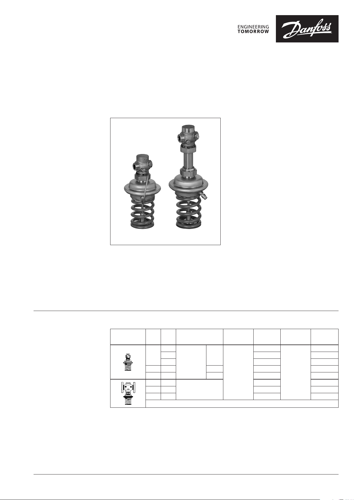
AVD AVDS
AVD(S) is a self-acting pressure reduction
controller primarily for use in district heating
systems. The controller is normally opened and
closes on rising pressure.
The controller has a control valve, an actuator
with one control diaphragm and a spring(s) for
pressure setting.
1-5 bar / 3-12 bar
• Temperature:
- Steam/circulation water/glycolic water
up to 30 %: 2 … 200 °C
• Connections:
- External thread (weld-on, thread and flange
tailpieces)
Ordering
Example 1 - AVD controller:
Pressure reduction controller for
water, DN 15, kVS 4.0, PN 25, setting
range 1-5 bar, T
ext. thread
- 1× AVD DN 15 controller
Code No: 003H6644
Option:
- 1× Weld-on tailpieces
Code No: 003H6908
The controller will be delivered
completely assembled, inclusive
impulse tube bet ween valve and
actuator.
max
150 °C,
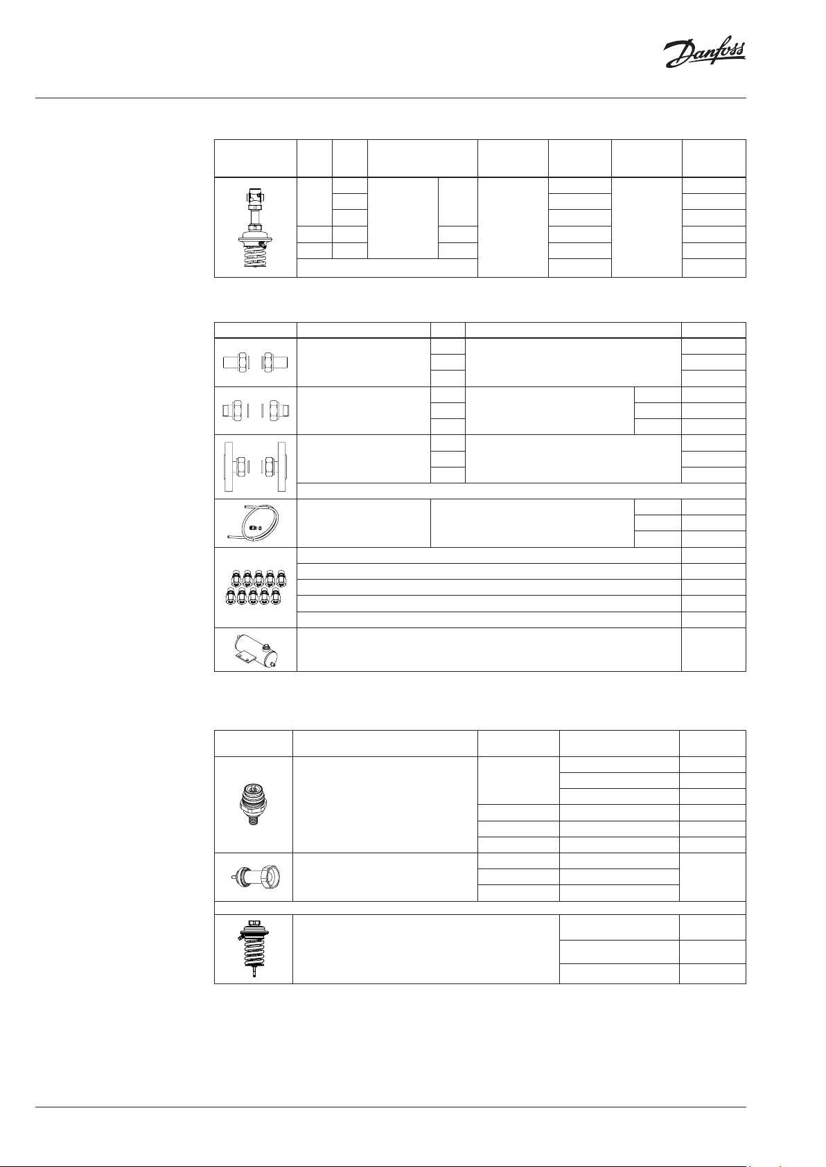
AVD Controller
DN
k
Picture
Note: othe r controllers available on s pecial request.
(mm)
VS
(m3/h)
0.4
15
1.0 003H6958 003H6979
4.0 003H664 4 003H6650
20 6.3 G 1 A 003H6645 003H66 51
25 8.0 G 1¼ A 003H6646 003H6652
32 12. 5
40 20 003H6660 003H6663
50 25 003H6661 003H6664
Connection
Cylindr. ext.
thread acc. to
ISO 228/1
Flanges PN 25,
acc. to EN 1092-2
G ¾ A
Pressure
setting range
(bar)
1-5
Code No.
003H6957
003H6659 003H6662
Pressure
setting range
(bar)
3-12
Code No.
003H6978
© Danfoss | 2020.05 AI083286470175en-000504 | 1
Page 2
Data sheet Pressure reduction controllers AVD(S) (PN 25)
Ordering (continuous)
Example 2 - AVD S controller:
Pressure reduction controller for
steam, DN 15, kVS 3.2, PN 25, setting
range 1-5 bar, T
ext. thread
- 1× AVDS DN 15 controller
Code No: 003H6667
- 1× Impulse tube set AV ⁄
Code No: 003H6852
Option:
- 1× Weld-on tailpieces
Code No: 003H6908
- 1× Seal pot
Code No: 003H0277
The controller will be delivered
completely assembled. External
impulse tube (AV) and seal pot must
be ordered separately.
200 °C,
max
AVDS Controller 1)
Picture
DN
(mm)
k
VS
(m3/h)
Connection
Pressure
setting range
(bar)
1.0
15
1.6 003H6666 003 H6671
Cylindr. ext.
3.2 003H6667 0 03H6672
thread acc. to
20 4.5 G 1 A 003H6668 003H6673
ISO 228/1
G ¾ A
25 6.3 G 1¼ A 003H6669 0 03H6 674
1)
Seal pot has to be us ed on impulse tubes always i n steam applications when T
1-5
≥ 150 °C
max
Code No.
003H6665
Pressure
setting range
(bar)
3-12
Accessories
Picture Type designation DN Connection Code No.
15
Weld-on tailpieces
20 003H6909
25 00 3H6910
15
External thread tailpieces
Conical ex t. thread acc. to
20 R ¾ 003H 6903
EN 1022 6-1
25 R 1 003H6904
15
Flange tailpieces
Flanges PN 25, acc. to EN 1092-2
20 003H 6916
25 0 03H6 917
Description:
-
Impulse tube set AV
1× copper tube Ø 6 × 1 × 1500 mm
- 1× compression fitting) for imp.
connection to pipe Ø 6 × 1 mm
1)
10 compression f ittings for impulse tube connection to pipe, Ø 6 × 1 mm R ⁄ 003H6857
1)
10 compression f ittings for impulse tube connection to pipe, Ø 6 × 1 mm R ⁄ 003H6858
1)
10 compression f ittings for impulse tube connection to pipe, Ø 6 × 1 mm R ½ 003H6859
1)
10 compression f ittings for impulse tube connection to actuator, Ø 6 × 1 mm G ⁄ 003 H6931
Shut off valve Ø 6 mm 003H0276
-
tube
R ½ 003H6902
R ⁄ 003H 6852
R ⁄ 003H6 853
R ½ 003H6854
Code No.
003H 6670
003H6908
003H6915
2)
Seal pot, 0.3 l, with two compression fittings Ø 6 × 1 mm 003H0277
1)
Compression f itting consists of a nipple , compression ring and nut.
2)
Seal pot has to be us ed on impulse tubes always i n steam applications when T
Service kits
Picture Type designation DN
1)
32/4 0/50 12.5/20/25 003H6876
2)
Actuator with setting spring
1)
for AVD controller on ly
2)
for AVDS controller o nly
Valve insert
Valve body extension with stuf fing box
≥ 150 °C
max
k
VS
(m3/h)
Code No.
0.4 003H6869
15
1.0 003H6 870
4.0 003H6873
20 6.3 0 03H6 874
25 8.0 003H6875
15 3.2
003H687720 4.5
25 6.3
Pressure setting range
(bar)
Code No.
1-5 003H684 4
3-12 003H6845
2 | AI083286470175en-000504 © Danfoss | 2020.05
Page 3
Data sheet Pressure reduction controllers AVD(S) (PN 25)
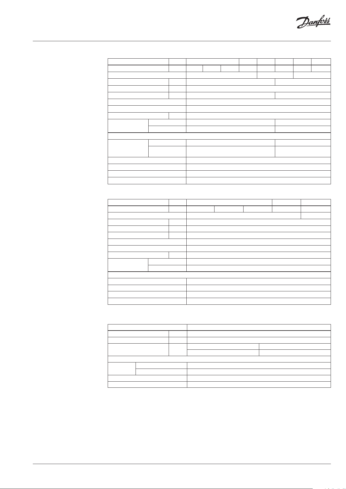
Technical data
Valve (AVD)
Nominal diameter DN 15 20 25 32 40 50
kVS value m3/h 0.4 1.0 4.0 6.3 8.0 12. 5 20 25
Cavitation factor z ≥ 0.6
Leakage acc. to standard IEC 534 % of k
VS
≤ 0.02
≥ 0.55 ≥ 0.5
≤ 0.05
Nominal pressure PN 25
Max. differential pressure bar 20 16
Medium Circulation water / glycolic water up to 30 %
Medium pH Min. 7, max. 10
Medium temperature °C 2 …150
Connections
valve External thread Flange
tailpieces Weld-on, external thread and flange -
Materials
thread Red bronze CuSn5ZnPb (Rg5) -
Valve body
flange -
Ductile iron
EN-GJS-400-18-LT (GGG 40.3)
Valve seat Stainless steel, mat. No. 1.4571
Valve cone Dezincing free brass CuZn36Pb2As
Sealing EPDM
Pressure relieve system Piston
Valve (AVDS)
Nominal diameter DN 15 20 25
k
value m3/h 1.0 1.6 3.2 4.5 6.3
VS
Cavitation factor z ≥ 0.6 ≥ 0.55
Leakage acc. to standard IEC 534 % of k
VS
Nominal pressure PN 25
Max. differential pressure bar 10
Medium Steam / Circulation water / glycolic water up to 30 %
Medium pH Min. 7, max. 10
Medium temperature
Connections
°
C 2 … 200
valve External thread
tailpieces Weld-on, external thread and flange
Materials
Valve body Red bronze CuSn5ZnPb (Rg5)
Valve seat Stainless steel, mat. No. 1.4571
Valve cone Stainless steel, mat. No. 1.4122
Pressure relieve system Bellows
1)
Seal pot has to be us ed on impulse tubes always i n steam applications when T
≥ 150 °C
max
≤ 0.02
1)
Actuator
Typ e AVD, AV DS
Actuator size cm
Nominal pressure PN 25
Pressure set ting ranges and
spring colours
Materials
Actuator
housing
Upper casing of diaphragm Stainless steel, mat. No.1.4301
Lower casing of diaphragm Dezincing free brass CuZn36Pb2As
Diaphragm EPDM
Impulse tube Copper tube Ø 6 × 1 mm
bar
2
54
1-5 3-12
blue black , green
AI083286470175en-000504 | 3© Danfoss | 2020.05
Page 4

Data sheet Pressure reduction controllers AVD(S) (PN 25)
Application principles
Direct-connected heating system Indirectly connected heating system
Installation positions Up to medium temperature of 100 °C the
controllers can be installed in any position (valid
for AVD controller only).
For higher temperatures (valid for AVD
controller) and always in steam applications
(AVDS controller) the controllers have to be
installed in horizontal pipes only, with a pressure
actuator oriented downwards.
4 | AI083286470175en-000504 © Danfoss | 2020.05
Page 5

Data sheet Pressure reduction controllers AVD(S) (PN 25)
Pressure temperature
diagram
AVD
AVDS
Sizing
②
①
① CuSn5ZnPb (Rg5) PN 25
② EN-GJS- 400-18-LT (GGG 40.3) PN 25
Maximum allowed operating pressure as a function of medium temperature (according to EN 1092-2 and EN 1092-3).
Pressure reduction controller has to control
6.0 bar behind the controller. Max. flow through
The min. differential pressure across the
controller is calculated from the formula:
①
the system is less than 2.0 m3/h, min. flow
pressure is 7.5 bar.
Given data:
Q
= 2.0 m3/h
max
p
= 7.5 bar
1 min
p
= 6.0 bar
reduced
Nominal pressure PN 25
p
= p
AVD
p
AVD
kv value is calculated according to formula:
k
v
− p
1 min
= 1.5 bar
Q
max
p
AVD
reduced
0,2
5, 1
= 7.5 − 6.0
kv = 1.6 m3/h
Solution:
The example selects AVD DN 15, kVS value 4.0,
with pressure setting range 3-12 bar
AI083286470175en-000504 | 5© Danfoss | 2020.05
Page 6

Data sheet Pressure reduction controllers AVD(S) (PN 25)
Design
1. Valve body
2. Valve insert
3. Pressure relieved valve cone
4. Valve stem
5. Control diaphragm
6. Setting spring for pressure
control
7. Adjuster for pressure setting,
prepared for sealing
8. Union nut
9. Upper casing of diaphragm
10. Lower casing of diaphragm
11. Air space bore
12. Impulse tube
13. Compression fitting for
impulse tube
14. Actuator
15. Valve body extension
16. Stuffing box
AVDAVD AVDSAVDS
Function The pressure behind of the control valve is being
transferred through the impulse tube to the
actuator chamber and act on control diaphragm.
On the other side of the diaphragm atmospheric
pressure is acting (through air space bore).
Control valve is normally opened. It closes on
rising pressure and opens on falling pressure to
maintain constant pressure.
Settings Pressure setting
Pressure setting is being done by the adjustment
of the setting spring for pressure control. The
adjustment can be done by means of spring for
pressure setting and/or pressure indicators.
6 | AI083286470175en-000504 © Danfoss | 2020.05
Page 7

Data sheet Pressure reduction controllers AVD(S) (PN 25)
Dimensions
L
1
L
3
2
H
H
H
1
H
L
2
H
H*
L
1
Ø 12 5
Ø 12 5
Ø 12 5
Ø 12 5
AVD AVD AVD AVD
DN 15-25 DN 32-50 DN 15-25 DN 32-50
∆p = 1-5 bar ∆p = 1-5 bar ∆p = 3-12 bar ∆p = 3-12 bar
L L
DN
15 65 - 215 275 - - 34 - 3.5 3.7
20 70 - 215 275 - - 34 - 3.5 3.7
25 75 - 215 275 - - 37 - 3.7 3.8
32 - 180 - - 250 320 - 70 10. 2 10.4
40 - 200 - - 250 320 - 75 11. 8 11. 9
50 - 230 - - 250 320 - 82 13 .9 14. 0
Note: Other fla nge dimensions - see table for tai lpieces.
H H* H1H1* H
1
mm 1-5 bar 3 -12 ba r
H
2
Weight (kg)
3
3
H
*
1
H
L
L
2
H
H
Ø 12 5
Ø 12 5
AVDS AVDS
DN 15-25 DN 15-25
∆ p = 1-5 bar ∆p = 3-12 bar
DN
L H H* H
mm 1-5 b ar 3-12 bar
15 65 290 345 34 3.5 3.7
20 70 290 345 34 3.5 3.7
25 75 290 345 37 3.7 3.9
2
Weight (kg)
2
H
H*
AI083286470175en-000504 | 7© Danfoss | 2020.05
Page 8

Data sheet Pressure reduction controllers AVD(S) (PN 25)
Dimensions (continuous)
L
3
L
2
L
1
d
2
n
k
SW
R
1)
SW d L
SW
SW
2)
L2L
1
k d
3
mm
45°
2
n
d
DN R
15 ⁄ 32 (G ⁄A) 21 130 131 13 9 65 14 4
20 ⁄ 41 (G 1A) 26 150 14 4 154 75 14 4
25 1 50 (G 1⁄A) 33 160 160 159 85 14 4
32 100 18 4
40 110 18 4
50 125 18 4
1)
Conical ex t. thread acc. to EN 10226-1
2)
Flanges PN 25, acc. to EN 1092-2
Seal potCompression fittings
31 mm (R ⁄)
R ⁄; R ⁄; R ⁄
37 mm (R ⁄)
43 mm (R ⁄)
L
Ø 55
© Danfoss | DHS-SMDBT/SI | 2020.058 | AI083286470175en-000504
 Loading...