

Data sheet Automatic bypass control AVDO
Application
Ordering
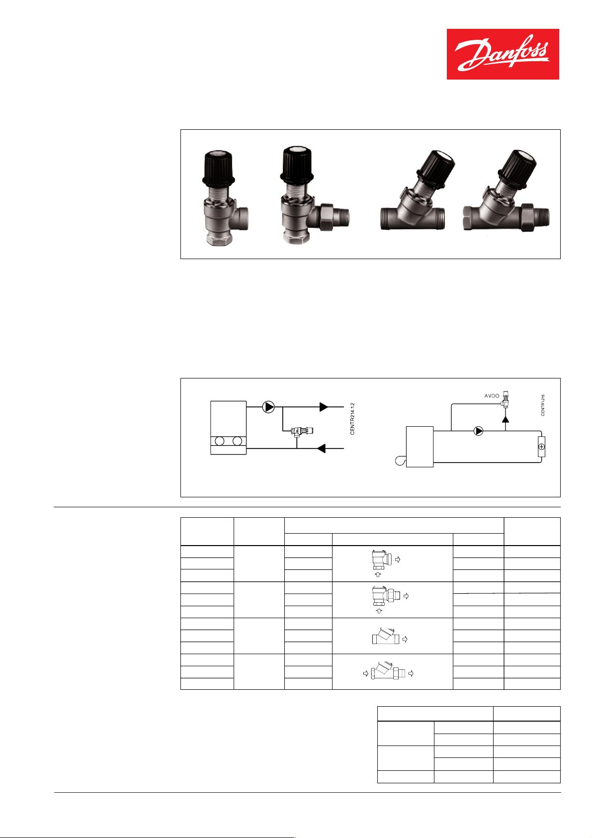
AVDO is a self-acting constant flow control
primarily used either to maintain minimum
flow rates through e.g. a low-capacity gas
boiler or to control the differential pressure in
- is dimensioned for pressure stage PN 10,
max. 120 °C
- DN 15 and DN 20
- operates without impulse tubes
a central heating system.
On delivery valve housing is fit onto AVDO
AVDO:
- opens on rising differential pressure
- has a setting range of 0.05 - 0.5 bar
with one of the following fittings: internal
socket thread, internal socket thread/nipple or
external thread for compression fittings.
Princip
Low-capacity gas boiler where maintenance of
a min. flow is required
Setting Connection
Type range Code no.
AVDO 15 R
AVDO 20 0,05 - 0,5 R
AVDO 25 R
AVDO 15 R
AVDO 20 0,05 - 0,5 R
AVDO 25 R
AVDO 15 G 3/4 A
AVDO 20 0,05 - 0,5 G 1 A
AVDO 25 G 1 1/4 A
AVDO 15 R
AVDO 20 0,05 - 0,5 R
AVDO 25 R
1)
According to ISO 7/1
2)
According to ISO 228/1
bar Inlet Outlet
1)
1/2
p
1)
3/4
p
1)
1
p
1)
1/2
p
1)
3/4
p
1)
1
p
2)
2)
2)
1)
1/2
p
1)
3/4
p
1)
1
p
Differential pressure control
1)
Rp 1/2
Rp 3/4
1)
Rp 1
1)
R 1/2
1)
R 3/4
1)
R 1
G 3/4 A
G 1 A
2)
003L6002
1)
003L6007
003L6012
003L6003
003L6008
003L6013
2)
003L6020
003L6025
G 1 1/4 A 2)003L6030
1)
R 1/2
R 3/4
R 1
1)
1)
003L6018
003L6023
003L6028
Accessories (supplied in boxes of 10)
Copper tube fittings Code no.
AVDO 15
AVDO 20
AVDO 25 Æ 28 x 1 13U0140
Æ 16 x 1 13U0131
Æ 18 x 1 13U0132
Æ 18 x 1 13U0134
Æ 22 x 1 13U0135
BC-HM VD.55.K6.02 © Danfoss 3/96 1
Data sheet Automatic bypass control AVDO
Technical data Setting range............................. 0.05 - 0.5 bar
Max. differential pressure..................... 0.5 bar
Operation pressure ...............................PN 10
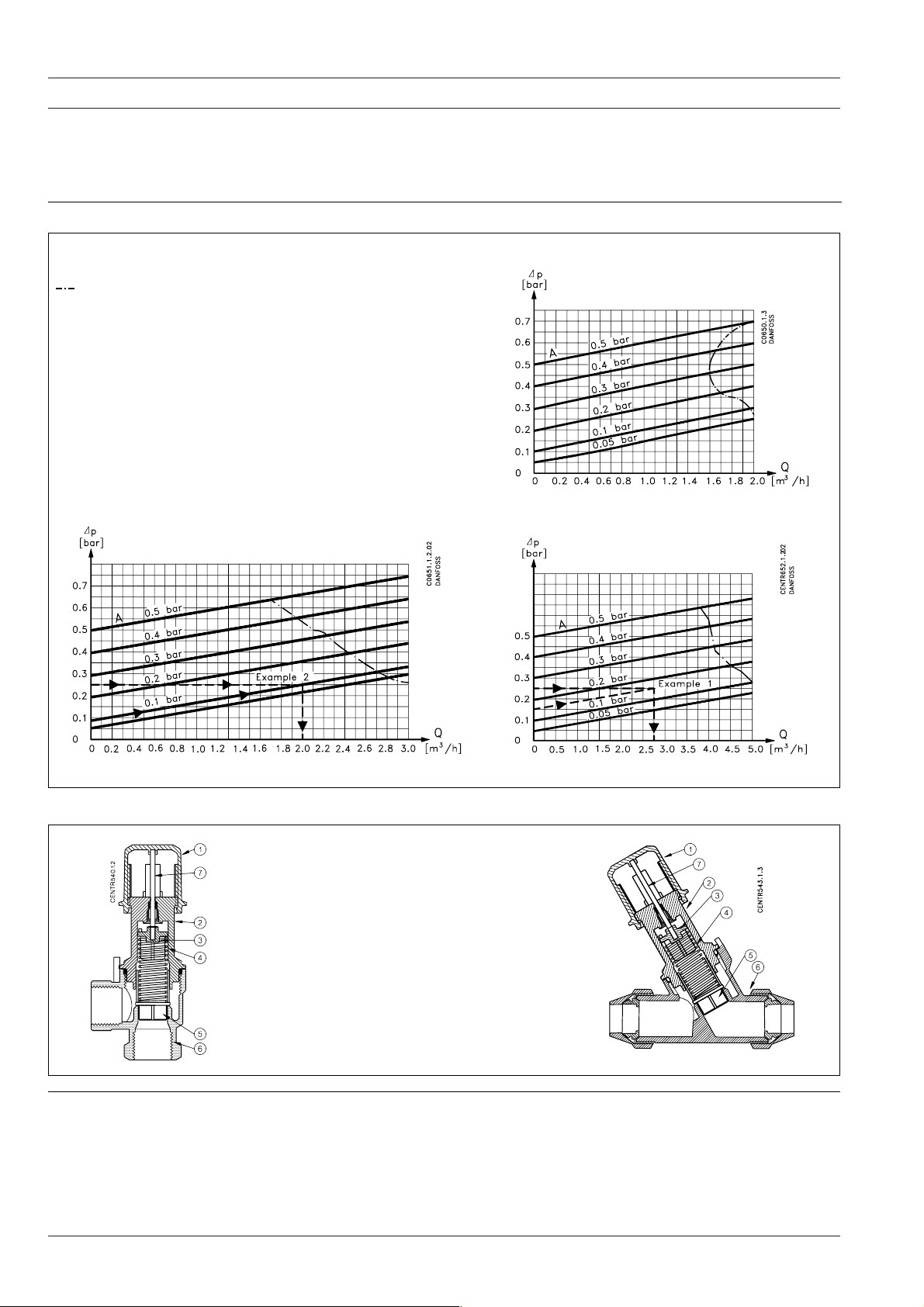
Capacity
A = set opening pressure
Dp=Dp for valve
= Upper limit graph for recommended application area
with almost noiseless installation. Measurement
conditions according to ISO 3743.
Max. flow temperature .........................120 °C
Max. leakage at closed valve................. 50 l/h
AVDO 15
AVDO 20
Design
Installation
Materials of parts in contact with water
➀
Setting handle Pom-plast
➁ Base Ms 58
➂ Spring guide Polyphenylene sulphide
(PPS-plastics)
➃ Spring Stainless steel
➄ Valve cone Polyphenylene sulphide
(PPS-plastics)
➅ Valve body Ms 58, hot-pressed
➆ Setting pin Stainless steel
O-rings EPDM rubber
The valve body must be mounted with flow in
direction of the cast-in arrow.
AVDO 25
2 VD.55.K6.02 © Danfoss 3/96 BC-HM

Data sheet Automatic bypass control AVDO
Setting The control is set by turning the setting dial.
AVDO has a setting scale on which the
opening pressure in bar or mwg can be
directly read. The differential pressures stated
Sizing
Fig. 1
Example 1
Bypass control across heating system
Given:
- System, see fig. 1
- Insignificant pressure loss in pipe from
boiler to bypass
- Pump characteristic, see fig. 2
- 0.15 bar system differential pressure at
max. system load
Required:
- Bypass circulation beginning at 0.15 bar
pump pressure
- Min. 2.0 m
3
/h boiler circulation
Seek:
- A constant flow control that opens
concurrently with falling load across the
system (closing radiator thermostats)
- A constant flow control that ensures min.
3
/h boiler circulation at min. system
2.0 m
load
Solution:
A 2.0 m
3
/h flow corresponds to a 0.25 bar
pump pressure.
On closing radiator thermostats AVDO is to
ensure min. 2.0 m
3
/h circulation at 0.25 bar
differential pressure across AVDO.
3
Choose AVDO 25 that provides 2.75 m
/h at
0.25 bar differential pressure across valve.
Set AVDO on 0.15 bar required opening
pressure.
for a given setting are indicative. The scale
gives the differential pressure across the
AVDO when it just begins to open.
Fig. 3
Example 2
Bypass control across circulation pump
Given:
- System, see fig. 3
- Pump characteristic, see fig. 4
Required:
- Bypass circulation beginning at 0.1 bar
pump pressure
- Max. system differential pressure at
closed radiator thermostats must be
limited to 0.25 bar.
Seek:
- A constant flow control that opens
concurrently with falling load across the
system (closing radiator thermostats)
- A constant flow control that ensures max.
system differential pressure not exceeding
0.25 bar at min. system load
Solution:
The max. permissible differential pressure
0,25 bar across system corresponds to a
3
/h water volume (fig. 4). At min. load
1.8 m
AVDO must ensure 1.8 m
3
/h pump bypass
circulation. In this example AVDO 20 must be
used - see "Capacity".
As circulation is not to begin before
differential pressure across system has
exceeded 0.1 bar, AVDO is set on 0.1 bar see "Setting.
Fig. 2
BC-HM VD.55.K6.02 © Danfoss 3/96 3
Fig. 4

Data sheet Automatic bypass control AVDO
Dimensions
DN Type a 1)b 1)L3 L4 L5 H1 S1 S2
15 AVDO 15 R
20 AVDO 20 R
25 AVDO 25 R
DN Type a b 2)L1 L2 H S
15 AVDO 15
½R ½406933831122830
p
¾R ¾427437831123437
p
1R1468146851144340
p
mm min. max.
Æ15/Æ16/Æ18
G ¾ A 87 111 89 113 30
min. max.
20 AVDO 20 Æ18/Æ22 G 1 A 93 120 90 114 37
25 AVDO 25 Æ28 G 1¼ A 106 136 95 119 45
1)
Acording to ISO 7/1
2)
Acording to ISO 228/1
DN Type a 1)L3 L5 H1 S1
min. max.
15 AVDO 15 Rp ½ 40 33 83 112 28
20 AVDO 20 Rp ¾ 42 37 83 112 34
25 AVDO 25 R
DN Type a 1)b 1)L1 L2 H S1 S2
15 AVDO 15 R
20 AVDO 20 R
25 AVDO 25 R
½ R ½ 87 116 89 113 28 30
p
¾ R ¾ 93 125 90 114 34 37
p
1 R 1 106 141 95 119 43 40
p
1 46 46 85 114 43
p
min. max.
4 VD.55.K6.02 © Danfoss 3/96 BC-HM
 Loading...