

Page 1
Data sheet
Differential pressure relief controller
AVDA - internal thread, PN 10
AVDSA - internal thread, PN 16
Description
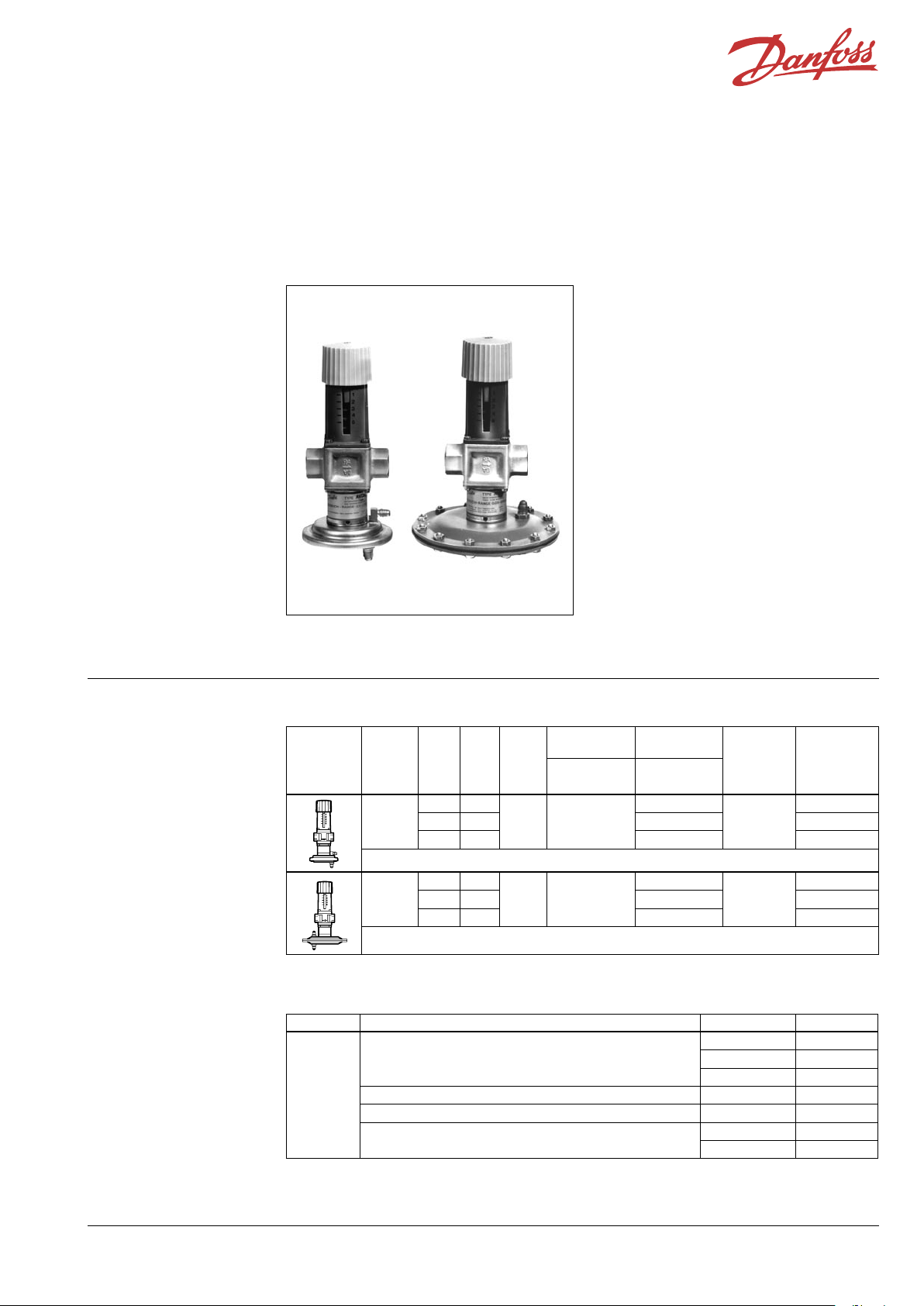
AVDA AVDSA
Ordering AVDA, AVDSA Controller
Example:
Differential pressure relief
controller, DN 15, kvs 1.9, PN 16,
setting range 0.05 - 0.5, t
int. thread
- 1x AVDSA DN 15 controller
Code No: 003N8204
max
130°C,
Picture Type DN
AVDA
AVDSA
AVDA and AVDSA are self-acting temperature
controllers used for constant flow control or
bypass control. Controller opens on rising
differential pressure.
The controller has a control valve, an actuator
with one control diaphragm and handle for
differential pressure setting.
For apartment block heating, district heating
plant and central heating systems.
Main data:
• DN 15, 20, 25
• kvs 1.9, 3.4, 5.5
• PN 10, 16
• Setting range:
0.1 - 1.2 bar (AVDA)
0.05 - 0.5 bar (AVDSA)
• Temperature:
- Circulation water / glycolic water up to 30%:
2 … 130 °C
• Connections: Int. thread
k
vs
m3/h
15 1.9
20 3.4 Rp ¾ 003N0039
25 5.5 Rp 1 003N0040
15 1.9
20 3.4 Rp ¾ 003N8205
25 5.5 Rp 1 003N8206
Setting range
PN
bar
10 0.1 - 1.2
16 0.05 - 0.5
Connection
- valve
Int. thread
ISO 7/1
Rp ½
Rp ½
Connection
Impulse
tube flare
7/16-20 UNF
7/16-20 UNF
Code No.
003N0038
003N8204
1)
2)
2)
1)
The code no. in cludes 2 impulse tube s (0.5 and 1.5 m) with tailpi eces.
2)
Available on r equest
Service kits
Picture Type designation for Code No.
Repair set
Two diaphragms, two O-rings, one rubber cone,
one tube of grease and eight valve cover screws
Brass-dipped nipple (two supplied as standard) AVDA, AVDSA 631X4700
Valve stuffing box AVDA, AVDSA 065F0006
Diaphragm housing
DH-SMT/SI VD.55. B1.02 © Danfoss 0 8/2006 1
DN 15 003N4006
DN 20 003N4007
DN 25 003N4008
AVDA 003N0065
AVDSA 003N0284
Page 2
Data sheet Differential pressure relief controllers AVDA (PN 10) and AVDSA (PN 16)
Technical data
Application principles
Nominal diameter DN 15 20 25
k
value m3/h 1.9 3.4 5.5
vs
Nominal pressure PN AVDA: 10, AVDSA: 16
Max. differential pressure bar
Medium Circulation water / glycolic water up to 30%
Medium pH Min. 7, max. 10
Medium temperature 2 … 130 oC
Materials
Valve body MS 58, hot-pressed, DIN 17660, W.No. 2.0402, CuZn40Pb2
Valve seat Cr Ni steel, DIN 17660, W.No. 1.4301
Valve cone NBR-rubber
Spindle Dezincing-free brass, BS 2874/CZ132
Diaphragm housing Zinc-cromated steel, DIN 1624, W.No. 1.0338
Diaphragm EPDM-rubber
7
Installation positions The valve body can be installed in any position.
A Danfoss FV strainer is recommended.
Impulse tubes have to be installed vertically
or horizontally onto the main pipe, never
downwards.
Needle valve can be installed between main pipe
and impulse tube, if necessary.
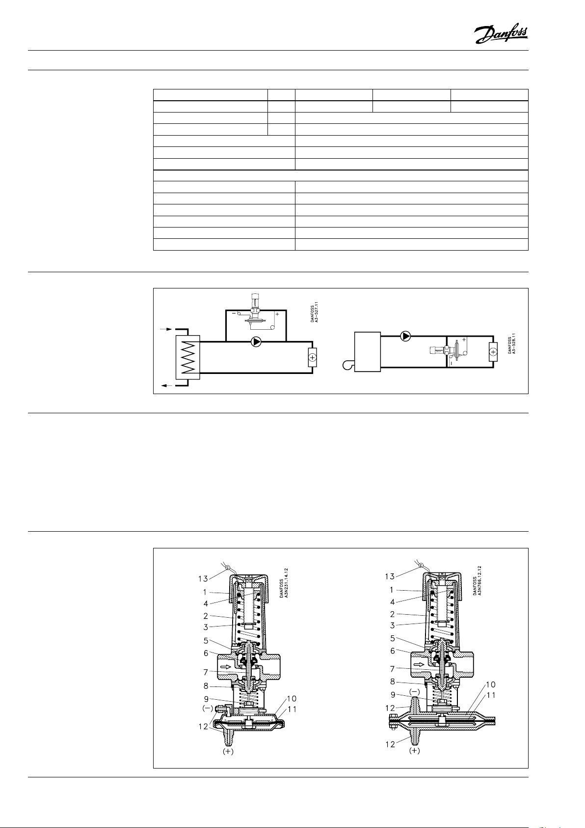
Design
1. Handle for differential
pressure setting
2. Spring housing
3. Setting spring
4. Spring guide
5. Diaphragm
6. Valve cone
7. Spindle
8. O-ring
9. O-ring gland
10. Diaphragm housing
11. Control diaphragm
12. Nipple for impulse tube
13. Lead seal
(+) impulse tube has to be connected to flow
line, (-) impulse tube has to be connected to
return line. Setting can be simplified by using
pressure indicators (manometers) placed close to
impulse tube connections.
By turning diaphragm housing downwards the
letter “RA” on valve housing must be oriented
upright.
AVDA AVDSA
2 VD.55. B1.02 © Danfoss 0 8/2006 DH-SMT/SI
Page 3
Data sheet Differential pressure relief controllers AVDA (PN 10) and AVDSA (PN 16)
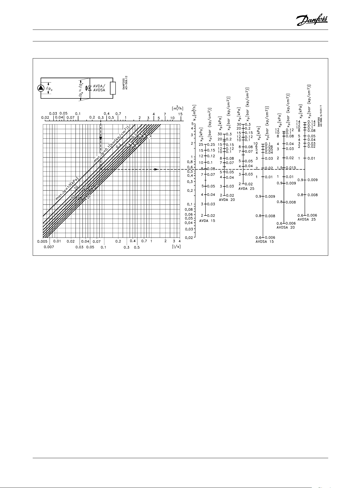
Sizing
Constant flow control
Example
Given
Assuming a pressure drop in the line from the
pump to and from the valve connections of nil
so that Δpp = Δpa = Δpv, the plant differential
pressure at max. load = 0.25 bar.
Condition
Maximum plant differential pressure with closed
radiator valves limited to 0.3 bar. Pump water
volume (Q) for this condition = 0.3 m3/h.
Required
A pressure relief control able to circulate a water
volume of at least 0.3 m3/h at Δpa = 0.3 bar and
which will remain closed under max. plant load,
Δpa = 0.25 bar.
Method
Locate the necessary water volume,
Q = 0.3 m3/h, on the horizontal axis in the
nomogram.
From the 0.3 m3/h point, take a vertical line up
to intersect the curve that gives the pressure at
which the valve must be completely open (here,
0,3 bar). From the intesection, take a horizontal
line to intersect the vertical axes on the right.
These axes give the pressure rise XP that is
necessary across the valve before it can give the
required capacity Q.
Since the pressure rise in this example is 0.3 -
0.25 = 0.05 bar, a valve where XP ≤ 0.05 bar could
be used, i.e. an AVDA 25.
This setting is therefore 0.25 bar, i.e. the valve is
closed when the differential pressure across it is
0.25 bar.
A pressure gauge can be used in making the
setting, or an approximate setting can be made
as shown in the associated installation example.
DH-SMT/SI VD.55. B1.02 © Danfoss 0 8/2006 3
Page 4
Data sheet Differential pressure relief controllers AVDA (PN 10) and AVDSA (PN 16)
Settings
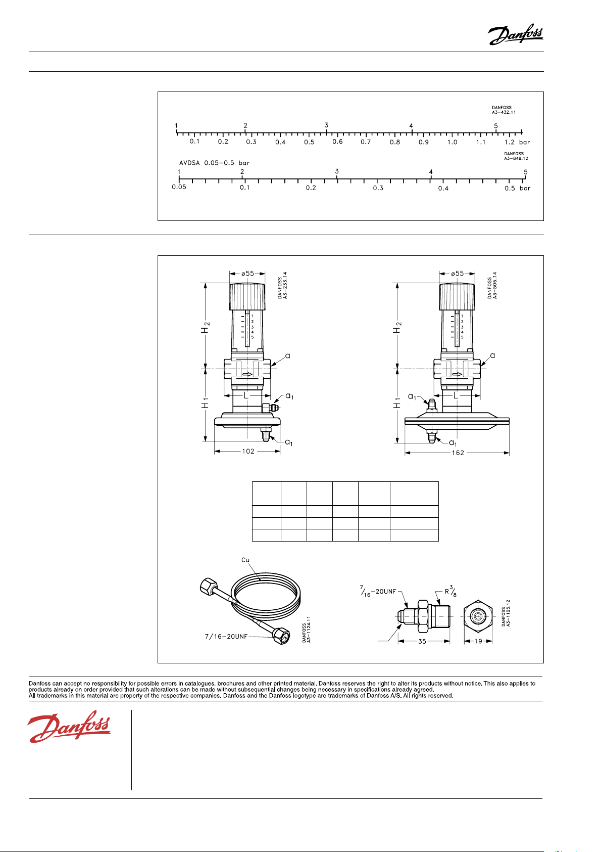
Dimensions
AVDA 0.1 - 1. 2 bar
Scale setting
Relation bet ween scale numbers and differential pressure.
The values given are indicative only.
AVDA AVDSA
H
H
1
Type
DN 15 112 133 72 Rp½ 7/16-20 UNF
DN 20 112 133 90 Rp¾ 7/16-20 UNF
DN 25 117 138 95 Rp1 7/16-20 UNF
Impulse tube Nipple
mm
2
mmL mmaISO 7/1
a1
flare
4 VD.55. B1.02 © Danfoss 0 8/2006 DH-SMT/SI
 Loading...