

Page 1
Data Sheet
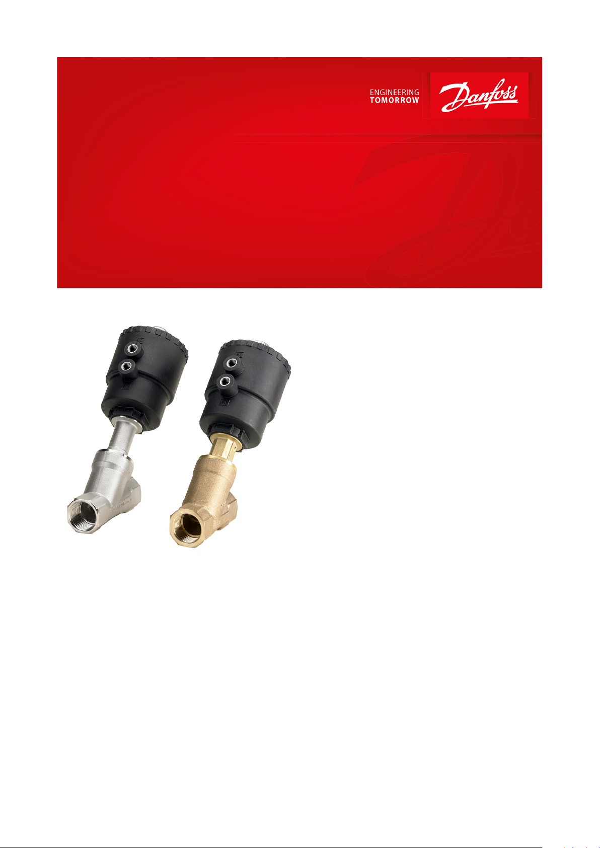
Angle-seat externally operated valve
Type AV210A - AV210H
For use in industrial applications
AV210 is an externally operated valve for use in
demanding industrial applications.
The valve can operate at very high medium
temperatures and viscosities, and is insensitive
to dirt particles in the medium; thus, it is often
called a “troubleshooter” valve. The valve is
available in bronze and stainless steel.
Features
• For all uids and gases
• Flow range: 0 – 234 m3/h / 0 – 275 USgal/min
• Unpressurized closed (NC) bidirectional
versions and unpressurized opened (NO)
version closing against the ow direction
• The valves can be used for rough vacuum
• Control connection G ⅛
• Valves comply with Pressure Equipment
Directive 97/23/EC
• NC version: bi-directional, closing against or
closing with the ow direction
• NO version: always closing against the ow
direction
AI222386434711en-000901
Page 2
Features
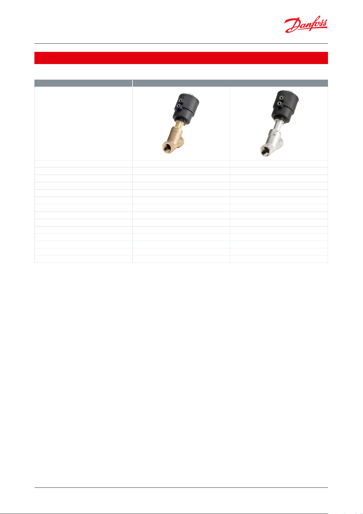
AV210
Body material
Brass
Stainless steel
DN [mm]
15-50
15-50
Connection ISO
G ⅜– G 2
G½-G2
Connection NPT (Only NC)
½-2
½-2
Sealing material
PTFE
PTFE
Function
NC, NO
NC, NO
Kv [m3/h]
4.5-67
4.9-67
Control head diameter [mm]
40, 50, 63, 90, 110
50, 63, 90, 110
Dierential pressure range [bar]
0-16
0-16
Control pressure NC [bar]
4-10
4-10
Control pressure NO [bar]
1.8-10
1.8-10
Function NC
Closing against and with the ow
Closing against and with the ow
Function NO
Only closing against the ow
Only closing against the ow
Temperature range [°C]
-30-180
-30-180
Angle-seat externally operated valve, type AV210A - AV210H
1 Portfolio overview
Table 1: Portfolio overview
© Danfoss | Climate Solutions | 2021.06 AI222386434711en-000901 | 2
Page 3
Danfoss
42N278.10
4
5
1
6
2
3
2
1
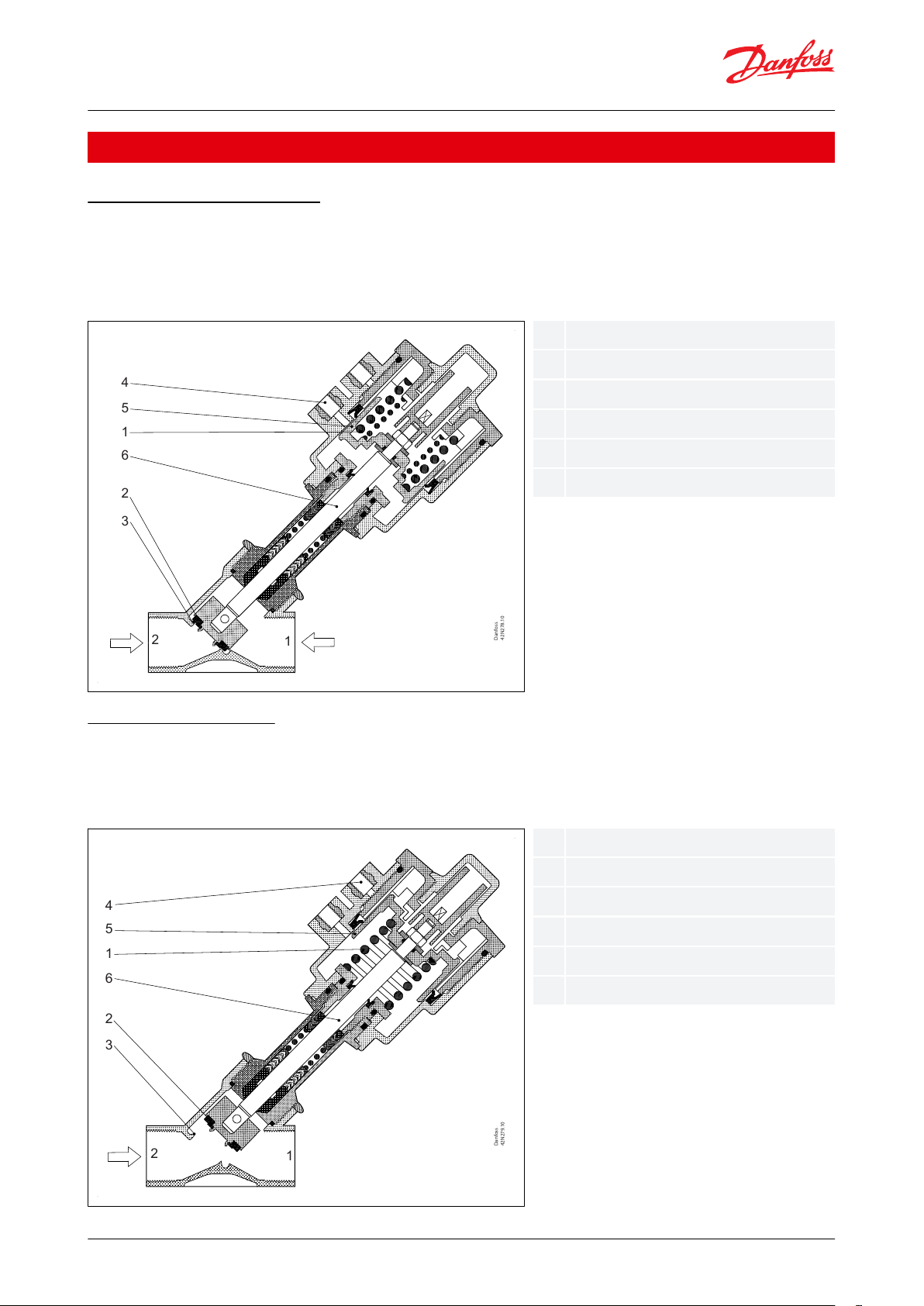
123456Spring
Seat gasket
Valve seat
Control connection
Control piston
Spindle
Danfoss
42N279.10
4
5
1
6
2
3
2
1
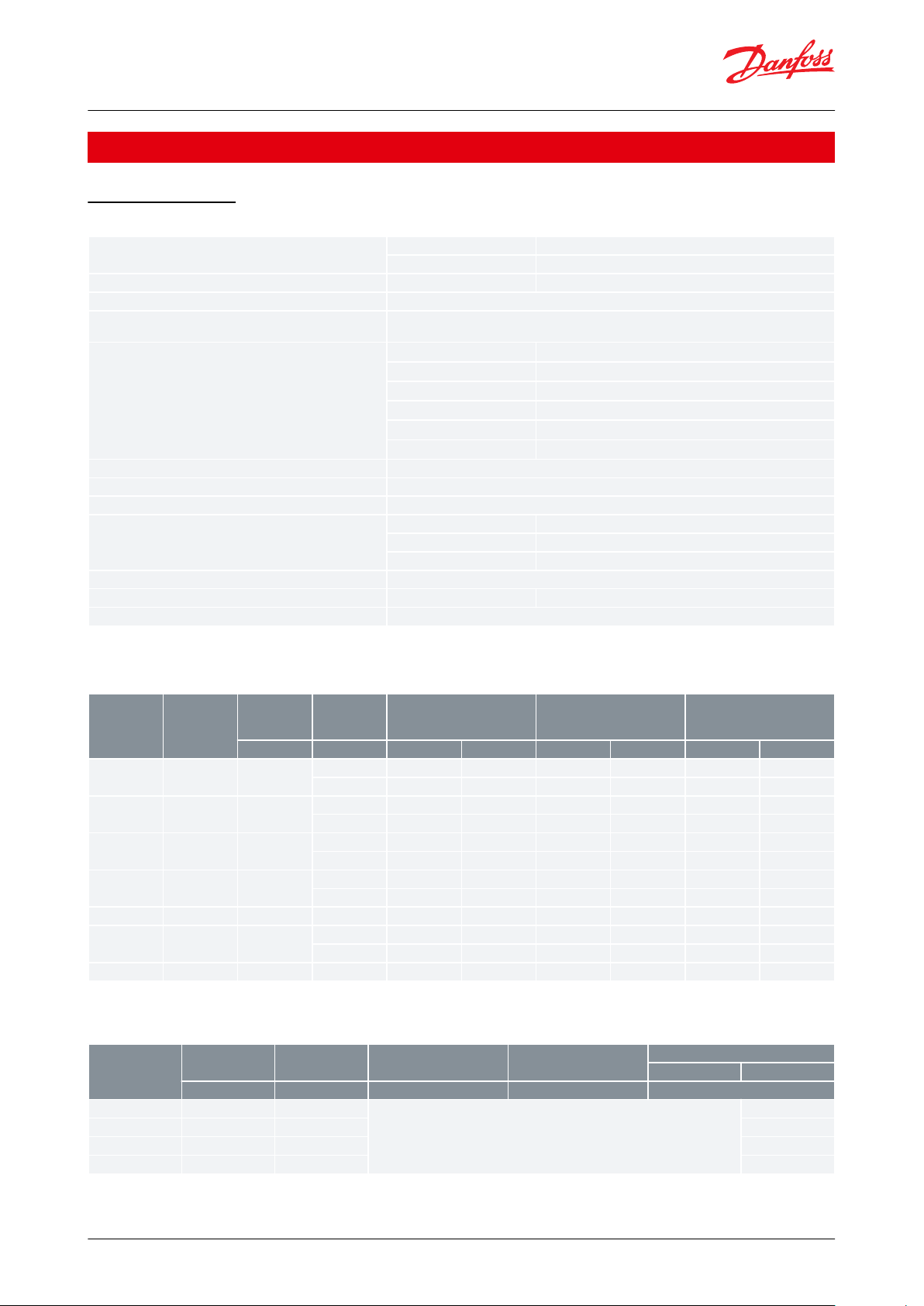
123456Spring
Seat gasket
Valve seat
Control connection
Control piston
Spindle
Angle-seat externally operated valve, type AV210A - AV210H
2 Functions
2.1 NC ISO / NPT Connection
AV210 unpressurized closed version (NC) bidirectional.
The valve is kept closed by the spring (1), which presses the seat gasket (2) against the valve seat (3). When the
pressure is applied to the control connection (4), the control piston (5), the spindle (6) and thus the seat gasket (2)
are raised, and the valve opens with or against the pressure of the medium.
2.2 NO ISO Connection
AV210 unpressurized open version (NO):
The valve is kept open by the spring (1), which keeps the seat gasket (2) away from the valve seat (3). When pressure
is applied to the control connection (4), the control piston (5), the spindle (6) and thus the seat gasket (2) are
lowered, and the valve closes against the pressure of the medium.
© Danfoss | Climate Solutions | 2021.06 AI222386434711en-000901 | 3
Page 4
Media
Bronze
For water, oil and compressed air
Stainless
For neutral, aggressive liquid and gaseous media
Media temperature [°C] / [°F]
PTFE
-30-180 °C /-22-356 °F
Ambient temperature [°C] / [°F]
-30-60 °C / -22-140 °F
Pressure
Pressure range can be extended for use in rough vacuum, typically up to 99% vacuum (10 mbar),
depending on the application
Kv value [m3/h]
DN15
4.5-5.7 m3/h
DN20
10 m3/h
DN25
20 m3/h
DN32
29 m3/h
DN40
46 m3/h
DN50
67 m3/h
Min. Opening dierential pressure [bar]
0 bar
Max. Opening dierential pressure [bar]
Up to 30 bar
Max. working pressure [bar]
Up to 30 bar
Max. test pressure [bar]
DN1.5-4.5
52.5 bar
DN6-10
37.5 bar
DN15-25
24 bar
Control medium
Air
Tightness
Internally / Externally:
Better than 0.4 mbar l/sec (25 ccm air per min.)
Viscosity [cSt]
Max. 600 cSt / 3000 SSU
Connection
ISO228/1
Connection
NPT
Orice
Control head
diameter
Max working pressure
Dierential pressure,
min. to max.
Control pressure
(1)
(Values for closing against
the ow)
[mm]
[mm]
[bar]
[psi]
[bar]
[psi]
[bar]
[psi]
G 3/8
15
4016232
0-16
0-232
4.2-10
61-1455016
232
0-16
0-232
4-10
58-145
G 1/2
1/2
15
4016232
0-16
0-232
4.2-10
61-1455016
232
0-16
0-232
4-10
58-145
G 3/4
3/4
20
5010140
0-10
0-140
4-10
58-1456316
232
0-16
0-232
4-10
58-145
G 1125
6311160
0-11
0-160
4-10
58-1459016
232
0-16
0-232
4-8
58-116
G 11/4
11/4329014203
0-14
0-203
4-8
58-116
G 11/2
11/2
40
9011160
0-11
0-160
4-8
58-116
11016232
0-16
0-232
4-8
58-116
G 2250
11010140
0-10
0-140
4-8
58-116
Connection
ISO228/1
Orice
Control head
diameter
Max working pressure
Dierential
pressure,
min. to max.
Control pressure
Min.
Max.
[mm]
[mm]
[bar]
[bar]
[bar]
G½1550
See gure 7 - 10 / Diagrams, NO for closing against the ow direction (Port 2 to 1)
10G¾205010G1256310
G1½4090
8
Angle-seat externally operated valve, type AV210A - AV210H
3 Product specication
3.1 Technical data
Table 2: Technical data
Dierential pressure range for NC/NO
Table 3: Dierential pressure NC, closing against the ow
(1)
(1)
For NC, closing with the
For NC, closing with the
Table 4: Dierential pressure NO, closing against the ow
ow: See gure 2 - 5 / Diagrams, NC for closing with the ow direction (Port 1 to 2)
ow: See gure 2 - 5 / Diagrams, NC for closing with the ow direction (Port 1 to 2)
© Danfoss | Climate Solutions | 2021.06 AI222386434711en-000901 | 4
Page 5
0
2
4
6
8
10
12
14
16
3/8”-1/2”
3/4”
3/8”-1/2”
0 1 2 3 4 5
Control pressure
Pressure
6 7 8 9 10
[bar]
[psi]
[bar]
[psi]
0
29
58
87
116
145
174
203
232
0
14.5 29 43.5 58
101.5
87
72.5 116
130.5
145
2 3 4 5 6 7 8 9 10
0
2
4
6
8
10
12
14
16
0 1
3/4”
1”
Control pressure
Pressure
[bar]
[psi]
[bar]
[psi]
0
29
58
87
116
145
174
203
232
0
14.5 29 43.5 58
101.5
87
72.5 116
130.5
145
2 3 4 5 6 7 8 9 10
0
2
4
6
8
10
12
14
16
0 1
1”
1 1/4”
1 1/2”
[bar]
[psi]
[bar]
[psi]
0
29
58
87
116
145
174
203
232
0
14.5 29 43.5 58
101.5
87
72.5 116
130.5
145
Control pressure
Pressure
2 3 4 5 6 7 8 9 10
0
2
4
6
8
10
12
14
16
0 1
1 1/2”
2”
Control pressure
Pressure
[bar]
[psi]
[bar]
[psi]
0
29
58
87
116
145
174
203
232
0
14.5 29 43.5 58
101.5
87
72.5 116
130.5
145
Danfoss
42N280.10
1
2
Angle-seat externally operated valve, type AV210A - AV210H
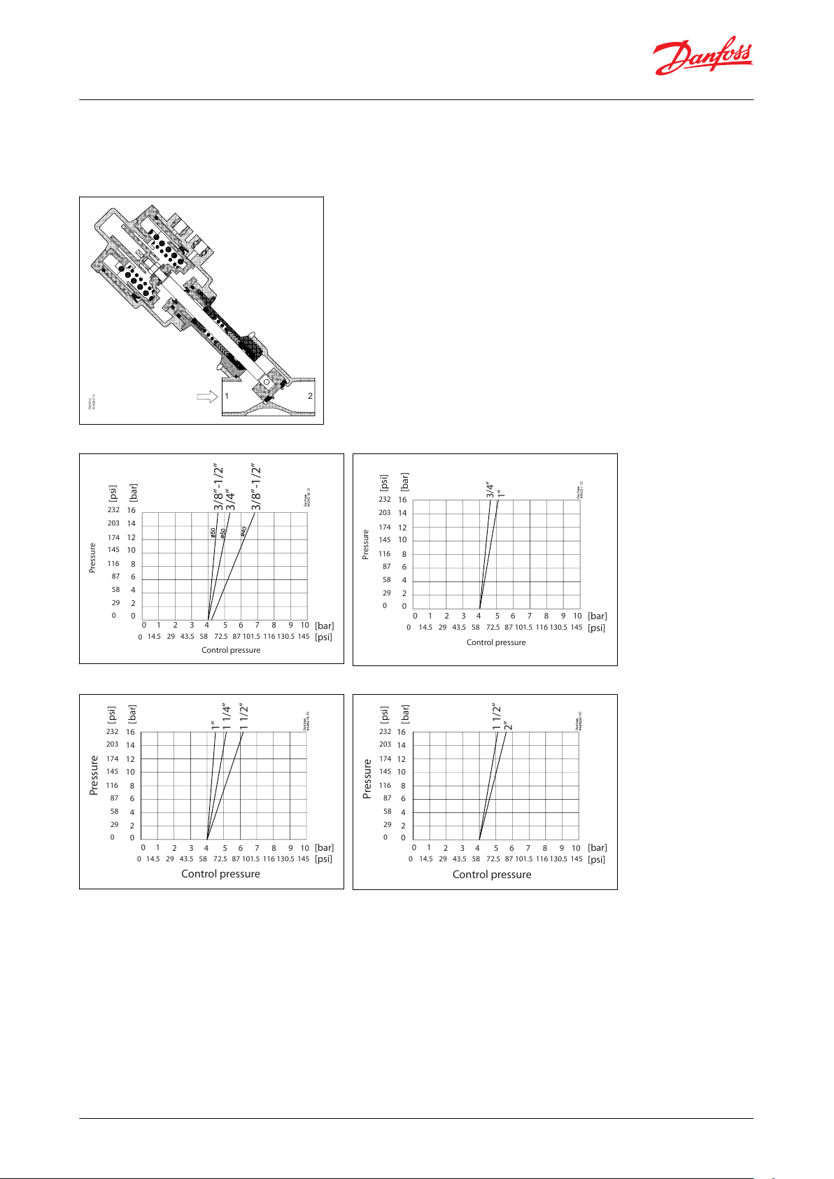
Diagrams, NC for closing with the ow direction (Port 1 to 2)
Recommended only for compressible media for extended pressure range
Figure 1: Valve connection
Figure 2: Control head ø40 - ø50 mm / 2 in
Figure 4: Control head ø90 mm / 3 ½ in
Figure 3: Control head ø63 mm / 2 ½ in
Figure 5: Control head ø110 mm / 4 ⅓ in
© Danfoss | Climate Solutions | 2021.06 AI222386434711en-000901 | 5
Page 6

Control pressure
Pressure
[bar]
[bar]
Control pressure
Pressure
[bar]
[bar]
Control pressure
Pressure
0
1 2 3 4 5 6 7 8 9 10 [bar]
0
2
4
6
8
10
12
14
16
[bar]
1 1/2”
Control pressure
Pressure
[bar]
[bar]
Danfoss
42N281.10
2
1
Angle-seat externally operated valve, type AV210A - AV210H
Diagrams, NO for closing against the ow direction (Port 2 to 1)
Figure 6: Valve connection
Figure 7: Control head ø50 mm
Figure 9: Control head ø90 mm
Figure 8: Control head ø63 mm
Figure 10: Control head ø110 mm
© Danfoss | Climate Solutions | 2021.06 AI222386434711en-000901 | 6
Page 7

AV 210 15 G/SS G1/2
AV210 15 G/SS G3/8
Main type
ø50 – 63 mm /
2 – 2 ½ in
control head
Closing with the
ow direction
ø50 – 63 mm /
2 – 2 ½ in
control head
Closing against the
ow direction
ø90 – 110 mm /
3 ½ – 4 ⅓ in
control head
Closing with the
ow direction
ø90 – 110 mm /
3 ½ – 4 ⅓ in
control head
Closing against
the ow direction
Time to open [ms]
(1)
40 – 180
50 – 350
80 – 780
100 – 460
Time to close [ms]
(1)
160 – 500
120 – 350
580 – 1270
360 – 790
Angle-seat externally operated valve, type AV210A - AV210H
Capacity diagram
Figure 11: Capacity diagram, Water
Time to open/close
Table 5: Time to open/close
(1)
(1)
The times are indicative.
The times are indicative.
© Danfoss | Climate Solutions | 2021.06 AI222386434711en-000901 | 7
Page 8

Components
Materials
Specications
Valve body
Bronze
RG 5
Stainless steel
AISI 316
Intermediate piece
Bronze
Brass
W.no.2.0402
Stainless steel
Stainless steel
AISI 316
Seat control and nut:
Stainless steel
AISI 316
Spindle
Stainless steel
AISI 316
Spindle gasket
PTFE
Gasket
Graphite
Valve plate unit
PTFE
Control head
PA66
Connec‐
tion ISO
228/1
Orice
size
Control
head di‐
ameter
ABC
D
D
1
øEFH
ch.L
Weight
[in]
[mm]
[mm]
[mm]
[mm]
[mm]
[mm]
[mm]
[mm]
[mm]
[mm]
[mm]
[kg]
G ⅜1540
144
121
13435-61651227
1.1
G ⅜1550
163
140
1534450.570651227
1.1
G ½1540
144
121
13435-61651327
1.0
G ½1550
163
140
1534450.570651327
1.0
G ¾2050
173
147
1634450.57075
14.3
27.5
1.2
G ¾2063
191
165
181
50.55784.47514.3
27.5
1.2
G 12563
206
176
196
50.55784.49017.5411.6
G 12590
246
216
236
66.2
72.7
116.49017.5411.7
G 1 ¼3290
255
220
245
66.2
72.7
116.4
1101950
3.0
G 1 ½4090
270
235
264
66.2
72.7
116.4
1201858
3.4
G 1 ½40110
306
271
300
77.4
83.9
140.6
1201858
4.0
G 250110
316
276
311
77.4
83.9
140.6
1502070
5.3
Conn.
NPT
Orice size
Control
head di‐
ameter
ABC
D
D
1
øEFH
ch.L
Weight
[in]
[mm]
[in]
[mm]
[in]
[mm]
[in]
[mm]
[in]
[mm]
[in]
[mm]
[in]
[mm]
[in]
[mm]
[in]
[mm]
[in]
[mm]
[in]
[mm]
[in]
[kg]
[lbs]
½15½502
163
6.4
140
5.5
153
6.0441.7
50.5
1.99702.8652.6130.5271.1
1.0
2.2¾15¾502173
6.8
147
5.8
163
6.4441.7
50.5
1.99702.8753.0
14.3
0.6
27.5
1.1
1.2
2.6125163
2 ½
206
8.1
176
6.9
196
7.7
50.5
2.0572.24
84.4
3.3903.5
17.5
0.7411.6
1.6
3.5
1 ¼321 ¼903 ½
255
10.0
220
8.7
245
9.6
66.2
2.6
72.7
2.86
116.4
4.6
110
4.3190.7502.0
3.0
6.6
1 ½401 ½903 ½
270
10.6
235
9.3
264
10.4
66.2
2.6
72.7
2.86
116.4
4.6
120
4.7180.7582.3
3.4
7.52502110
4 ⅓
316
12.4
276
10.9
311
12.2
77.4
3.0
83.9
3.30
140.6
5.5
150
5.9200.8702.8
5.3
11.7
Angle-seat externally operated valve, type AV210A - AV210H
Materials
Table 6: Materials
3.2 Dimension and weight
Dimension and weight, bronze valve body
Table 7: ISO Connection
Table 8: NPT Connection
© Danfoss | Climate Solutions | 2021.06 AI222386434711en-000901 | 8
Page 9

øE
Ch L
D
A
F
H
C
B
1/8” ISO 228/1
ISO 228/1
D
1
Namur
Key width 3 mm
Optional Namur flange for actuator ø50-110
16
16
12
14
12
6
44
52
4 x M5
Connec‐
tion ISO
228/1
Orice
size
Control
head di‐
ameter
ABC
D
D
1
øEFH
ch.L
Weight
[in]
[mm]
[mm]
[mm]
[mm]
[mm]
[mm]
[mm]
[mm]
[mm]
[mm]
[mm]
[kg]
G ⅜1540190
156
16944-70851225
1.1
G ½1550
190
156
1694450.570851525
1.0
G ¾2050
195
160
1764450.57095
16.3311.2
G ¾2063
213
178
194.4
50.57084.49516.3311.2
G 12563
219
182
202
50.57084.4
105
19.5381.6
G 12590
259
222
242
66.2
72.7
116.4
105
19.5381.7
G 1 ¼3290
266
226
249
66.2
72.7
116.4
1201947
3.0
G 1 ½4090
271
230
258
66.2
72.7
116.4
1301854
3.4
G 1 ½40110
307
266
294
77.4
83.9
140.6
1301854
4.0
G 250110
321
276
310
77.4
83.9
140.6
1502066
5.3
Conn.
NPT
Orice size
Control
head di‐
ameter
ABC
D
D
1
øEFH
ch.L
Weight
[in]
[mm]
[in]
[mm]
[in]
[mm]
[in]
[mm]
[in]
[mm]
[in]
[mm]
[in]
[mm]
[in]
[mm]
[in]
[mm]
[in]
[mm]
[in]
[mm]
[in]
[kg]
[lbs]
½15½502
190
7.5
156
6.1
169
6.7441.7
50.5
1.99702.8853.3150.6251.0
1.0
2.2¾15¾502195
7.7
160
6.3
176
6.9441.7
50.5
1.99702.8953.7
16.3
0.6311.2
1.2
2.6¾15¾63
2 ½
213
8.4
178
7.0
194.4
7.7
50.5
2.0572.24
84.4
3.3953.7
16.3
0.6311.2
1.2
2.6125163
2 ½
219
8.6
182
7.2
202
8.0
50.5
2.0572.24
84.4
3.3
105
4.1
19.5
0.8381.5
1.6
3.5
1 ¼321 ¼903 ½
266
10.5
226
8.9
249
9.8
66.2
2.6
72.7
2.86
116.4
4.6
120
4.7190.7471.9
3.0
6.6
1 ½401 ½903 ½
271
10.7
230
9.1
258
10.2
66.2
2.6
72.7
2.86
116.4
4.6
130
5.1180.7542.1
3.4
7.52502110
4 ⅓321
12.6
276
10.9
310
12.2
77.4
3.0
83.9
3.30
140.6
5.5
150
5.9200.8662.6
5.3
11.7
Angle-seat externally operated valve, type AV210A - AV210H
Figure 12: Dimension
Dimension and weight, stainless steel valve body
Table 9: ISO Connection
Table 10: NPT Connection
© Danfoss | Climate Solutions | 2021.06 AI222386434711en-000901 | 9
Page 10

øE
Ch L
D
A
F
H
C
B
1/8” ISO 228/1
ISO 228/1
D
1
Namur
Key width 3 mm
Optional Namur flange for actuator ø50-110
16
16
12
14
12
6
44
52
4 x M5
Danfoss
42N286.10
Angle-seat externally operated valve, type AV210A - AV210H
Figure 13: Dimension
3.3 Mounting
NC
Mounting: Bi-directional
Closing against the ow (Port 2 to 1), recommended to avoid water hammer.
Closing with the ow direction (Port 1 to 2), recommended only for compressible uids for extended pressure range.
NO
Mounting
Closing against the ow (Port 2 to 1), recommended to avoid water hammer.
© Danfoss | Climate Solutions | 2021.06 AI222386434711en-000901 | 10
Page 11

Danfoss
42N288.10
Angle-seat externally operated valve, type AV210A - AV210H
© Danfoss | Climate Solutions | 2021.06 AI222386434711en-000901 | 11
Page 12
Connection
ISO228/1
Orice
Kv value
Control head
diameter
Sealing
Function
Bronze
SS
[mm]
[m3/h]
[mm]NCNONCNO
G ⅜
15
4.5
40
PTFE
042N4400
4.950042N4401
042N4450
G ½
15
5.340042N4402
5.750042N4403
042N4431
042N4451
042N4481
G ¾2010
50
042N4404
042N4432
042N4452
042N4482
63
042N4405
042N4453
G 12520
63
042N4406
042N4433
042N4454
042N4483
90
042N4407
042N4455
G 1¼322990042N4408
042N4456
G 1½4046
90
042N4409
042N4435
042N4457
042N4485
110
042N4410
042N4458
G 25067
110
042N4411
042N4436
042N4459
042N4486
Connection NPT
Orice
Flow value
Control head di‐
ameter
Sealing
Function
Bronze
SS
[mm]
Kv [m3/h]
Cv [USgal/ min]
[mm]NCNC
½155.7
6.5
50
PTFE
042N4503
042N4551¾201011.5
50
042N4504
042N4552125202363042N4506
042N45541¼32293390042N45081½40465390042N4509
042N45572506777
110
042N4511
042N4559
Angle-seat externally operated valve, type AV210A - AV210H
4 Ordering
4.1 Parts program
Table 11: Bronze/SS, AV210 with ISO thread connection NC/NO
Table 12: Bronze/SS, AV210 with NPT thread connection NC/NO
4.2 Accessories
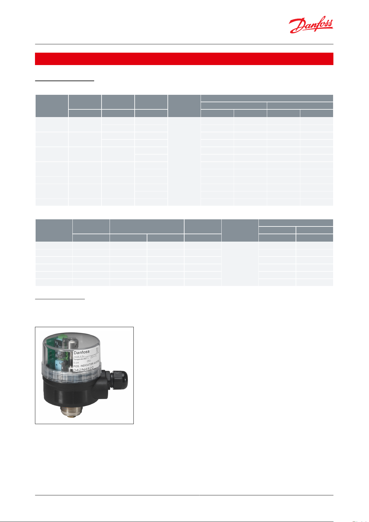
Position indicator
Figure 14: Position indicator
Features
The control box to check the open/closed positions with two mechanical limit switches is suitable for assembling on
the whole range of valves.
Level of protection : IP65
Ambient temperature: from -20 – 70 °C (-4 – 158 °F)
© Danfoss | Climate Solutions | 2021.06 AI222386434711en-000901 | 12
Page 13

Danfoss
42N283.10
95
ø70
A
A
Actuator size
A
Code number
[mm]
[in]
[mm]
[in]
ø50252.1
2.1
042N4820
ø632½47.5
1.9
042N4821
ø903½37.7
1.5
042N4822
ø1104⅓29.5
1.2
042N4823
Limit Switch
at the top:
open valve
Limit Switch
at the bottom:
closed valve
5
4
3
2
1 L
supply
Max. capacity 5 A 250 V AC
1 A 250 V DC
Angle-seat externally operated valve, type AV210A - AV210H
Access lead nr.2 PG11
Body material: Polyamide (cap in Lexan/polycarbonate)
Figure 15: Valve
Table 13: Position indicator ordering
* Limit Switch Box incl. 2 switches
Figure 16: Wiring diagram for position indicator
Namur ange
Namur ange for actuator ø50-110:
• for assembly of 3/2 solenoid valves
• according to EN 15714-3
Figure 17: Namur ange
© Danfoss | Climate Solutions | 2021.06 AI222386434711en-000901 | 13
Page 14

Danfoss
42N277.10
1
2
2
1
Actuator size
Code number
ø50-110
042N4811
Connection
Control head diameter
Material
Code number
ISO 228/1 [in]
NPT [in]
[mm]
Valve plate unit
Gasket
G ⅜40PTFE
Graphite
042N4800
G ⅜50PTFE
Graphite
042N4801
G ½40PTFE
Graphite
042N4802
G ½½50
PTFE
Graphite
042N4803
G ¾¾50 – 63
PTFE
Graphite
042N4804
G 1163
PTFE
Graphite
042N4805
G 190PTFE
Graphite
042N4806
G 1¼1¼90
PTFE
Graphite
042N4807
G 1½
1½
90 – 110
PTFE
Graphite
042N4808
G 22110
PTFE
Graphite
042N4809
Angle-seat externally operated valve, type AV210A - AV210H
Table 14: Namur ange ordering
Repair kit
The repair kit contains :
1.
Two gaskets (1) (On actuator size 40 (diameter control head) only one gasket included).
2.
One complete valve plate unit (plug and pin) (2).
NOTE:
One gasket is for bronze, and one is for stainless steel.
Figure 18: Kit Figure 19: Valve
Table 15: Repair kit ordering, bronze/stainless steel
Control valves, types EV310A and EV310B
Figure 20: Type EV310A Figure 21: Type EV310B
© Danfoss | Climate Solutions | 2021.06 AI222386434711en-000901 | 14
Page 15

Angle-seat externally operated valve, type AV210A - AV210H
• Valves for industrial applications
• Available in de-energized closed and de-energized open versions
• Available with or without manual operation
See separate data sheets regarding code numbers, technical data and coil options for Danfoss EV310A and EV310B
valves.
© Danfoss | Climate Solutions | 2021.06 AI222386434711en-000901 | 15
Page 16

5 Online support
Danfoss oers a wide range of support along with our products, including digital product information, software,
mobile apps, and expert guidance. See the possibilities below.
The Danfoss Product Store
The Danfoss Product Store is your one-stop shop for everything product related—no matter where
you are in the world or what area of the cooling industry you work in. Get quick access to essential
information like product specs, code numbers, technical documentation, certications, accessories,
and more.
Start browsing at store.danfoss.com.
Find technical documentation
Find the technical documentation you need to get your project up and running. Get direct access to
our ocial collection of data sheets, certicates and declarations, manuals and guides, 3D models
and drawings, case stories, brochures, and much more.
Start searching now at www.danfoss.com/en/service-and-support/documentation.
Danfoss Learning
Danfoss Learning is a free online learning platform. It features courses and materials specically
designed to help engineers, installers, service technicians, and wholesalers better understand the
products, applications, industry topics, and trends that will help you do your job better.
Create your Danfoss Learning account for free at www.danfoss.com/en/service-and-support/learning.
Get local information and support
Local Danfoss websites are the main sources for help and information about our company and
products. Find product availability, get the latest regional news, or connect with a nearby expert—all
in your own language.
Find your local Danfoss website here: www.danfoss.com/en/choose-region.
Spare Parts
Get access to the Danfoss spare parts and service kit catalog right from your smartphone. The app
contains a wide range of components for air conditioning and refrigeration applications, such as
valves, strainers, pressure switches, and sensors.
Download the Spare Parts app for free at www.danfoss.com/en/service-and-support/downloads.
Any information, including, but not limited to information on selection of product, its application or use, product design, weight, dimensions, capacity or any other
technical data in product manuals, catalogues descriptions, advertisements, etc. and whether made available in writing, orally, electronically, online or via download,
shall be considered informative, and is only binding if and to the extent, explicit reference is made in a quotation or order conrmation. Danfoss cannot accept any
responsibility for possible errors in catalogues, brochures, videos and other material. Danfoss reserves the right to alter its products without notice. This also applies to
products ordered but not delivered provided that such alterations can be made without changes to form, t or function of the product. All trademarks in this material
are property of Danfoss A/S or Danfoss group companies. Danfoss and the Danfoss logo are trademarks of Danfoss A/S. All rights reserved.
© Danfoss | Climate Solutions | 2021.06 AI222386434711en-000901 | 16
 Loading...