

Page 1
Technical Information
Automotive on PLUS+1®
for MC-024
powersolutions.danfoss.com
Page 2

Technical Information
Automotive on PLUS+1® for MC-024
Revision history Table of revisions
Date Changed Rev
Aug 2016 Updated order numbers 0202
Dec 2015 Converted to DITA CMS and Danfoss layout 0201
Mar 2012 Typos 0102
Dec 2011 First edition 0101
2 | © Danfoss | Aug 2016 L1120636 | 0202
Page 3

Technical Information
Automotive on PLUS+1® for MC-024
Contents
General Information
General Description, Electric and Electronics.........................................................................................................................4
Automotive-on PLUS+1 (AoP+1), system description...................................................................................................4
Automotive on PLUS+1 advanced functions....................................................................................................................4
Required Controller....................................................................................................................................................................4
Mode Types........................................................................................................................................................................................ 5
Hydrostatic propel methods...................................................................................................................................................5
Automotive Mode.......................................................................................................................................................................6
Non-Automotive Mode.............................................................................................................................................................7
Creep-Automotive Mode......................................................................................................................................................... 8
System modes and selection........................................................................................................................................................9
Application Function....................................................................................................................................................................10
General customer / sensor requirements..............................................................................................................................13
Drive / Creep / Joystick / Rocker and inch pedal...........................................................................................................13
Pressure inch sensor................................................................................................................................................................13
Mode switch A........................................................................................................................................................................... 14
Mode switch B............................................................................................................................................................................14
HST / Motor / PPU.....................................................................................................................................................................14
Pump displacement.................................................................................................................................................................14
Motor displacement and Brake Pressure defeat (BPD) ..............................................................................................14
Digital outputs 1, 2, 3, 4..........................................................................................................................................................14
Automotive Control connection diagram.............................................................................................................................15
Technical Specifications
Input signals: Power supply – Battery.................................................................................................................................... 16
Input signals: Forward-Neutral-Reverse (FNR) switch...................................................................................................... 17
Input signals: Mode switch.........................................................................................................................................................18
Input signals: Inch pedal..............................................................................................................................................................19
Input signals: Drive/Creep pedal, Joystick and Rocker pedal ....................................................................................... 20
Input signals: Motor speed sensor ..........................................................................................................................................21
Output signals: Pump displacement control.......................................................................................................................22
Output signals: Motor displacement and Brake Pressure Defeat (BPD) control.....................................................23
Output signals: Digital outputs 1, 2, 3, 4................................................................................................................................24
CAN Communication: Input and Output signals................................................................................................................25
Mating Connectors........................................................................................................................................................................26
Customer connector: 1, 2 (C1, C2)...................................................................................................................................... 26
CAN Bus adapter cable.................................................................................................................................................................27
AC Electrical Data & Characteristics.........................................................................................................................................27
Supply characteristics............................................................................................................................................................. 27
I/O characteristics.....................................................................................................................................................................28
Operating characteristics.......................................................................................................................................................29
Environmental and Protection characteristics...............................................................................................................29
©
Danfoss | Aug 2016 L1120636 | 0202 | 3
Page 4

Technical Information
Automotive on PLUS+1® for MC-024
General Information
General Description, Electric and Electronics
Automotive-on PLUS+1 (AoP+1), system description
The Automotive-on PLUS+1 is designed to control a single-path hydrostatic transmission system
consisting of one pump and one hydrostatic motor. The flexible system configuration allows use of a
wide range of hydrostatic pumps and motor configurations.
The AoP+1 is optimized for use with a hydrostatic motor equipped with Pressure Control Override (PCOR)
or Proportional (PROP) valve to control pressure or motor displacement. Additionally a Brake Pressure
Defeat (BPD) digital control valve can override the hydraulic pressure control during vehicle decelerating.
Parking Brake, Reverse Motion buzzer, Forward/Reverse-Lamp-Indicator, Retarder output and a Vehicle
speed controlled output can be controlled with additional four digital output. All functions may not be
available simultaneously.
The AoP+1 can read several analog, digital, and frequency signals representing operator input, system
demands, and machine status inputs.
The CAN Comunication Interface (SAE J1939) is used for diagnosis purposes and for information
exchanging with other controllers such as engine, or customer-controllers.
Automotive on PLUS+1 advanced functions
The Automotive-on PLUS+1 commands the basic vehicle driving behavior and performance (i.e.
acceleration, deceleration, and vehicle speed). The operator selects the driving mode, driving direction,
and basic transmission set point command via throttle or Creep/Drive pedal. An additional input, the inch
pedal command, can be used to override the basic transmission command.
A number of advanced features can be independantly activated and configured depending upon the
application.
Below is a list of the primary advanced functions:
Engine and Motor Over-Speed Protection
•
Engine Anti stall
•
Constant Speed Control
•
Vehicle Speed Limitation
•
Intelligent Operator Presence Detection
•
Maximum Motor Torque at Vehicle Start
•
Retarder control
•
Required Controller
The Automotive-on PLUS+1® application is designed for a specific MC024-121 “Automotive on PLUS+1® ”
with the order number 11177284.
4 | © Danfoss | Aug 2016 L1120636 | 0202
Page 5

Technical Information
Automotive on PLUS+1® for MC-024
General Information
Mode Types
Hydrostatic propel methods
The application software provides 3 different hydrostatic propel methods, defined as mode types, which
can be calibrated individually.
Automotive
•
Proportional pump (displacement) and motor (displacement or PCOR) control valve current is defined
by the Automotive Curve,
Non-Automotive
•
Drive-Pedal controlled proportional pump (Displacement) and motor (Displacement or PCOR) control
valve current, but Engine RPM independent,
Creep-Automotive
•
like “Automotive”, but Creep-Potentiometer limitation of the Automotive Curve of the pump.
Automotive and Creep-Automotive mode types are primarily intended for Wheel Loader and Telescopic
Handler applications.
The Non-Automotive mode type is primarily intended for Sweeper, Forestry, and Forklift applications.
Each selectable system mode can be configured as one of the 3 mode types (hydrostatic propel methods)
below:
Automotive Mode
•
Non-Automotive Mode
•
Creep-Automotive Mode; (combination of Automotive and Non-Automotive)
•
©
Danfoss | Aug 2016 L1120636 | 0202 | 5
Page 6
0
1
2
3
Current (mA)
Low idle
max.
4
5
6
7
Engine min-1(rpm)
The actual current is defined by the automotive curve
and therefore engine speed dependent
P003 532E
Engine min-1(rpm)
0
1
2
3
Low idle
The actual current is defined by the automotive curve
and therefore engine speed dependent
Motor at max. displacement
Motor at min. displacement
4
5
6
7
P003 561E
Current (mA)
32˚
6˚ (0˚)
constant
current
"STOP"
De-energized (no current) = Motor at min. displacement
H1B Motor controls M1, M2, K1, K2, T1,T2, P1, P2
Engine min-1(rpm)
Low idle
The actual current is defined by the automotive curve
and therefore engine speed dependent
Motor at min. displacement
Motor at max. displacement
P301 338E
Current (mA)
32˚
6˚ (0˚)
constant
current
"STOP"
De-energized (no current) = Motor at max. displacement
H1B Motor controls L1, L2, D1, D2, E1, E2
0
1
2
3
4
5
6
7
Technical Information
Automotive on PLUS+1® for MC-024
General Information
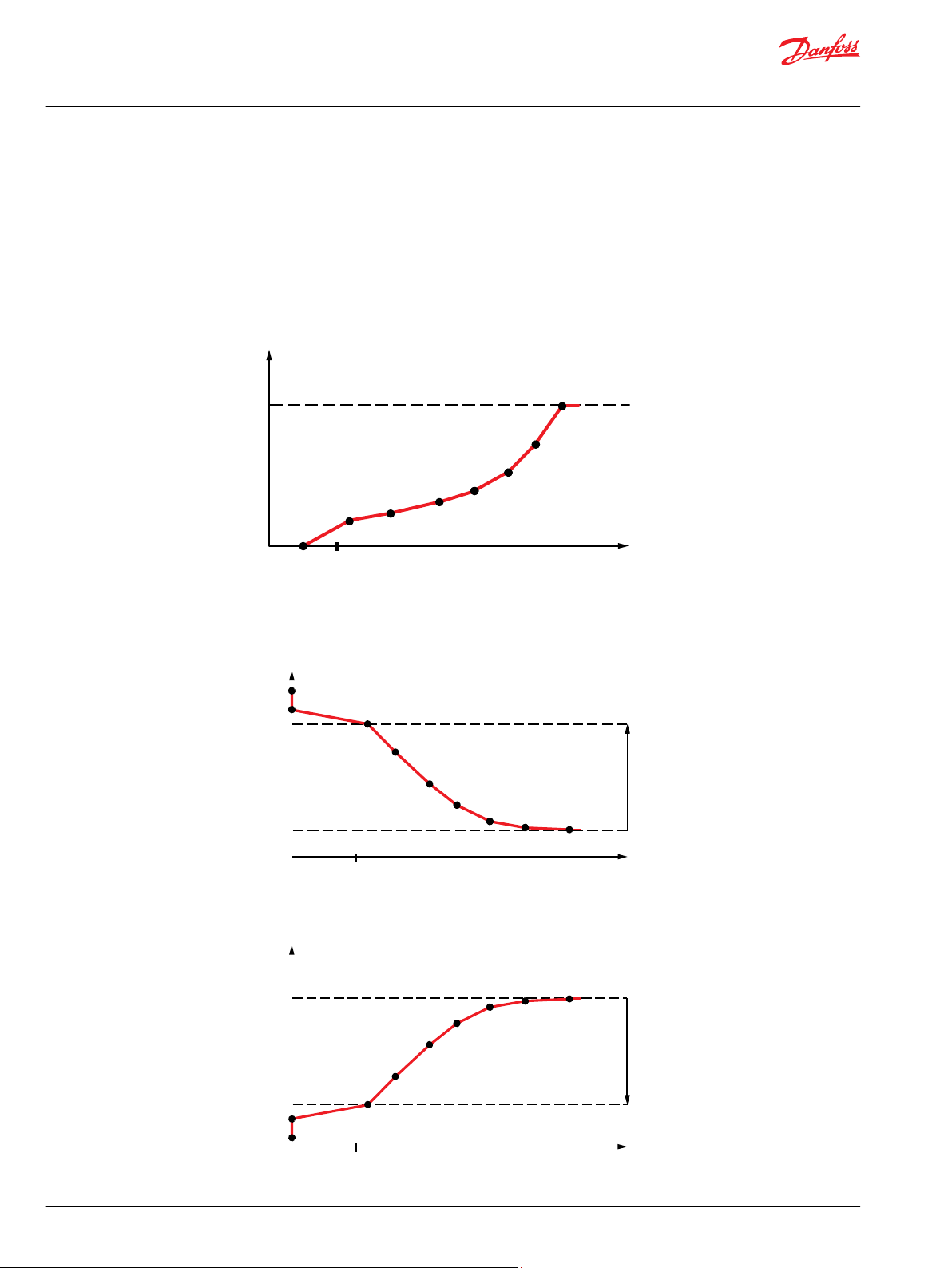
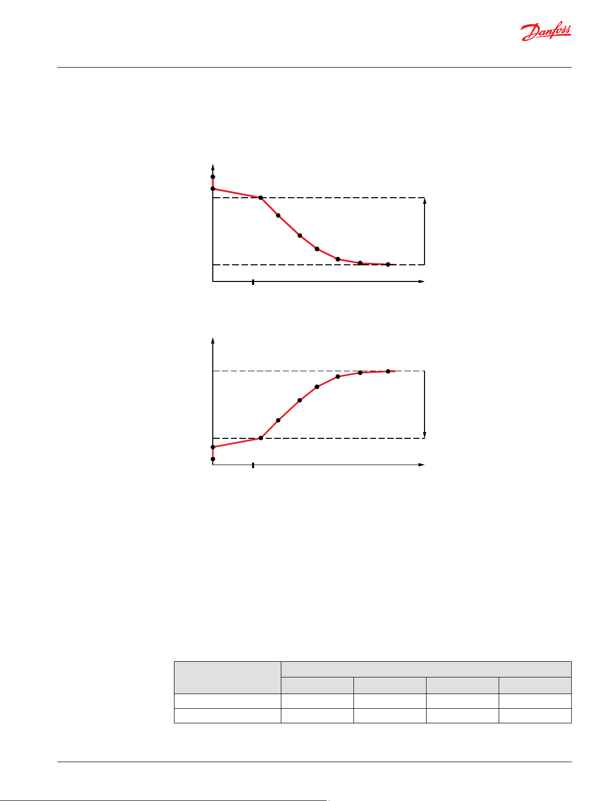
Automotive Mode
In Automotive Mode the current to the proportional valves is directly controlled by the measured engine
RPM. The current is independently parameter configurable for pump and motor in each mode. The
Automotive Mode provides good anti-stall behavior due to the load dependent control.
The profile curve (points 0-7) of the Automotive Mode drive curve are set according to the available
torque characteristics of the engine, accounting for additional auxiliary power.
Pump drive curve
Motor drive curve
6 | © Danfoss | Aug 2016 L1120636 | 0202
Page 7
Drive pedal position (%)
max.
P003 533E
0
2
3
100
4
5
6
7
1
Current (mA)
Drive pedal position (%)
P003 562E
0
1
2
3
100
4
5
6
7
Current (mA)
Motor at max. displacement
Motor at min. displacement
constant
current
"STOP"
32˚
6˚ (0˚)
De-energized (no current) = Motor at min. displacement
H1B Motor controls M1, M2, K1, K2, T1,T2, P1, P2
Drive pedal position (%)
P301 337E
0
1
2
3
100
4
5
6
7
Current (mA)
Motor at min. displacement
Motor at max. displacement
constant
current
"STOP"
32˚
6˚ (0˚)
De-energized (no current) = Motor at max. displacement
H1B Motor controls L1, L2, D1, D2, E1, E2
Technical Information
Automotive on PLUS+1® for MC-024
General Information
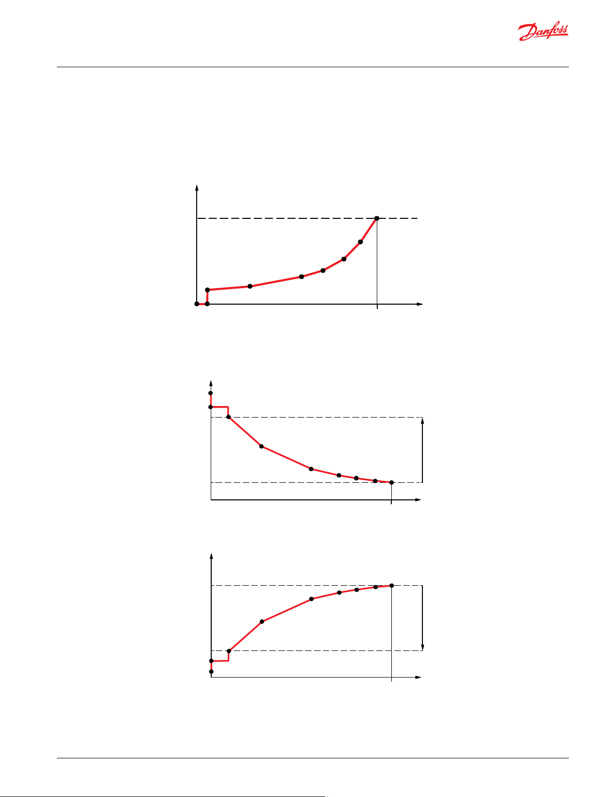
Non-Automotive Mode
The Non-Automotive Mode uses an analog input signal from the drive pedal to command vehicle speed.
The pump and motor valve currents are controlled by the system mode profile and are independent of
pump speed.
Pump drive curve
Motor drive curve
©
Danfoss | Aug 2016 L1120636 | 0202 | 7
Page 8
FNR in neutral = no current
FNR in FW or RV = current at
Creep Start RPM 1050 rpm
max.
Low
idle
825
1095
Engine rpm
Dotted line
represents x %
of Drive Pedal stroke,
the example about 40 %
“Creep“ pedal controls
current at any engine speed
thus controlling vehicle speed
point 5: 1500 - 825 = 675 mA
1050 min
-1
P003 534E
0
1
2
3
4
5
6
7
The actual current is defined by the automotive curve
and therefore engine speed dependent
Current (mA)
Technical Information
Automotive on PLUS+1® for MC-024
General Information
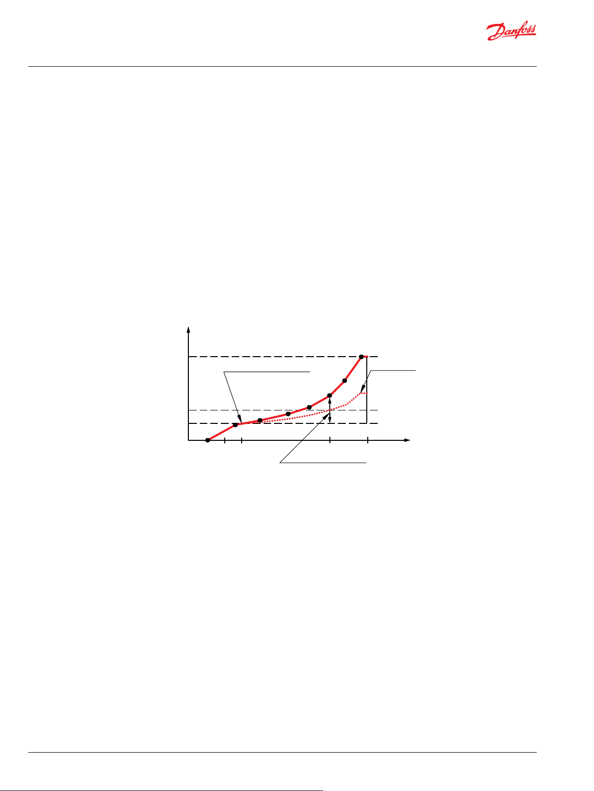
Creep-Automotive Mode
Creep-Automotive Mode is a combination of both Automotive and Non-Automotive Mode. Creep
Automotive Mode uses an analog input signal (Drive/Creep Potentiometer) to control the pump valve
current. The available pump valve current is limited by the automotive curve dedicated to this mode
type.
The actual current to the pump valve is the product of the actual engine RPM, the defined automotive
curve, and the actual percentage of Drive/Creep Potentiometer input. Creep-Automotive is active above
a user defined “Creep Start RPM”, below this RPM the propel system behaves like Automotive-Mode.
The motor valve current follows the automotive curve like in Automotive Mode.
Actual engine RPM = 1800 min-1 => I
Actual Pedal value = 40%;
Creep Start RPM = 1050 min-1 => I
I
= [(1500-I
Valve
Pump drive curve
CreepStart
CreepStart
) * 40 / 100] + I
Automotive-Curve
= 825 mA;
= 1095 mA
CreepStart
= 1500 mA;
8 | © Danfoss | Aug 2016 L1120636 | 0202
Page 9
Engine min-1(rpm)
0
1
2
3
Low idle
The actual current is defined by the automotive curve
and therefore engine speed dependent
Motor at max. displacement
Motor at min. displacement
4
5
6
7
P003 561E
Current (mA)
32˚
6˚ (0˚)
constant
current
"STOP"
De-energized (no current) = Motor at min. displacement
H1B Motor controls M1, M2, K1, K2, T1,T2, P1, P2
Engine min-1(rpm)
Low idle
The actual current is defined by the automotive curve
and therefore engine speed dependent
Motor at min. displacement
Motor at max. displacement
P301 338E
Current (mA)
32˚
6˚ (0˚)
constant
current
"STOP"
De-energized (no current) = Motor at max. displacement
H1B Motor controls L1, L2, D1, D2, E1, E2
0
1
2
3
4
5
6
7
Technical Information
Automotive on PLUS+1® for MC-024
General Information
Motor drive curve
System modes and selection
The application simultaneously supports up to 4 system modes. The system modes define the basic
characteristic of the transmission and are operator selectable via 2 digital inputs: Mode Switch A and
Mode Switch B.
Each of the four system modes can be:
optimized for driving behavior through independent drive curves with individual pump and
•
hydrostatic motor ramping.
configured as any one of the mode types (propel methods).
•
The following table describes the relationship between the digital input mode switches and the resulting
system modes:
Modes and selection
©
Danfoss | Aug 2016 L1120636 | 0202 | 9
Mode switch A Low Low High High
Mode switch B Low High Low High
System mode
Mode 1 Mode 2 Mode 3 Mode 4
Page 10

Technical Information
Automotive on PLUS+1® for MC-024
General Information
Application Function
Application function description
Description
1. Independent Pump/Motor-Profiling & Ramping
Both the pump and motor can be independently configured for the forward and reverse driving direction. The application software facilitates
individual command profiles (8 points) based on pump RPM or drive pedal inputs. Additionally vehicle acceleration timing (1 ramp) and
deceleration timing (3 ramps plus 1 error ramp) are independently configurable.
2. 4 Selectable System-Modes
The application supports 4 configurable System Modes which are selectable with digital inputs Mode Switch A and Mode Switch B. Each
System Mode can be individually configured through Mode Type (Automotive, Creep-Automotive, Non-Automotive) and all advanced
functions (e.g. CSD, Antistall, Overspeed Protection, etc).
3. Configurable System-Mode- & Direction-Change
This function allows configuration of an application specific System Mode transition. The System Mode change condition can be dependent
on multiple factors including actual FNR Direction, Drive Pedal Input, and Ground Speed.
The vehicle driving direction change can be configured on vehicle speed.
When a momentary FNR switch logic is configured, the driving direction change request is rejected if the vehicle speed is above a predefined
speed.
4. Configurable Operator-Presence-Detection (only via CAN-BUS)
In primary configuration, an open seat switch (operator not in the seat), programmable with or without time delay, will trigger vehicle shut
down. In secondary configuration, the open seat switch requires an secondary operator presence indicator, such as the release of throttle,
drive pedal, or inch pedal, to trigger vehicle shut down
5. Pump Displacement Control:
The software provides a displacement control for NFPE (Non-Feedback Proportional Electric) or EDC (Electrical Displacement Control) pumps.
The pump command can be definded by a profile curve which can be dependent on engine speed (Automotive Mode, Creep-Automotive
Mode) or the drive pedal (Non-Automotive Mode) The current change (stroke time) is configurable by ramps during initial vehicle set up.
6. Motor Displacement Control: Proportional, Variable-PCOR or Two-Position
The software facilitates Motor Displacement Control for Proportional, Variable PCOR, and Two Position control types. The motor command can
be defined by a constant value or a profile curve which can be dependent on engine speed (Automotive Mode, Creep-Automotive Mode) or
the drive pedal (Non-Automotive Mode). The motor valve current change (stroke timing) is configured by ramps defined during initial vehicle
set up.
7. Motor BPD-Control
The Motor Brake Pressure Defeat Control prevents the activation of the internal motor control pressure compensator (PCOR) during
deceleration events. The Motor BPD Control activation can be configured individually for driving direction. For change of driving direction the
control timing can be configured as state change or actual motor direction dependent.
8. Brake Test Mode
The Brake Test Mode allows the hydrostatic transmission system to drive against the applied park brake and can be individually configured for
each System Mode.
The Brake Test Mode cannot be used during normal operation.
9. Parking-Brake-Control
The Parking Brake Control digitally activates (apply/release) a park brake. Park brake activation can be vehicle speed dependent with
additional dependency on:
•
Software machine state in STOP mode
•
Actual pump valve current below user defined value
•
Actual inch pedal command exceeds user defined value.
Delay times for park brake application and release are individually configurable.
10. Reverse-Driving-Direction-Buzzer-Output
The Reverse Driving Direction Buzzer Output controls a buzzer that indicates reverse driving direction. The output logic can be directly
controlled by FNR status or by actual propel movement.
11. Forward- and Reverse-Direction-LED Output
The Forward and Reverse Direction LED Output function digitally drives LEDs as driving direction indicators for use in dashboard/display and is
directly linked to the FNR status.
12. Fault-Status-Output (Red-LED)
The Fault Status Output provides an output signal of the internal fault status/error code capable of digitally driving an LED.
10 | © Danfoss | Aug 2016 L1120636 | 0202
Page 11

Technical Information
Automotive on PLUS+1® for MC-024
General Information
Application function description (continued)
Description
13. Brake-Light-Output
The Brake Light Output digitally drives an indicator lamp (within the specified hardware output limits) when the inch pedal command exceeds
a user defined value.
14. Vehicle-Speed-Dependent Output-Signal
The Vehicle Speed Dependent Output Signal toggles a digital output when the actual vehicle speed exceeds an user defined speed.
15. Retarder Control (Engine Speed Dependent Output-Signal)
The Engine Speed Dependent Output-Signal toggles a digital output when the actual engine speed exceeds an user defined speed. It can be
used to control a retarder function to support the braking capability of the engine.
16. Safety controlled Vehicle Start-Protection
To release the start-protection the following signals will be checked:
•
Engine RPM
•
Battery voltage
•
Error status
•
Inch calibration
•
FNR in neutral
17. Engine Anti-Stall especially for Non-Automotive (All- & Fixed-Pump Speed Range)
The Engine Anti-Stall prevents the engine from being stalled due to overload through the transmission system. There are two independent
Engine Anti-Stall Modes: Fixed-Engine-RPM and All-Range Engine RPM.
Fixed-Engine-RPM: Fixed-Engine-RPM anti-stall is used in applications operating at fixed engine speeds. If the actual pump speed droops
below the target fixed engine speed the software PI-Controller will reduce the pump valve current to achieve/maintain the target fixed engine
speed.
All-Range-Engine-RPM: The engine speed command and the actual pump speed will be compared to calculate the engine speed droop. If
the actual pump speed is below the user defined engine speed droop the software PI-controller will reduce the pump valve current to reduce
engine load and prevent further engine speed droop.
The Engine Anti-Stall can be individually enabled for each System Mode.
18. Engine Over Speed Protection (EOP) during inching
This protection function is only activated while inching and if the actual pump (engine) speed is above the configured “Start RPM”. If this
configured speed is exceeded, the inching command is reduced towards 0 proportional to engine speed increase. Once inching command is
reduced to 0 further engine speed increases cannot be controlled.
In case of engine over-speed due to downhill driving (exceeding the braking performance of the engine) mechanical brakes are needed to
protect the engine.
19. Vehicle Constant-Speed-Drive (CSD) via drive pedal command and motor speed sensor (Non-Automotive only)
The CSD function (“CSD by pedal command”) compares the drive pedal command for vehicle speed with the actual vehicle speed. Actual
vehicle speed is calculated using measured motor speed, gear ratio, and wheel diameter where 100 % Pedal Position is the maximum vehicle
speed in either the forward or reverse direction. If the actual vehicle speed differs from the commanded speed, the software PI-Controller will
adjust the pump valve current to compensate for the speed difference.
This function can be individually System Mode enabled and configured.
This function requires motor or vehicle speed sensor.
20. Vehicle CSD (Constant-Speed-Drive) via measured pump rpm command (calculated flow) and motor speed sensor (Automotive &
Creep-Automotive only)
This CSD function (“CSD by pump flow”) calculates pump flow via pump speed and predicted pump swash plate angle. Swash plate angle is
predicted based on factory calibrated pump valve current relationship (e.g. 800 mA = 0°, 1200 mA = 18°). The software will calculate the
desired motor speed based on the predicted swash plate angle, actual pump rpm, and the max. motor displacement.
If the actual vehicle speed differs from the commanded speed, the software PI-Controller will adjust the pump valve current to compensate for
the speed difference.
This function requires motor or vehicle speed sensor but can be used without a drive pedal input.
21. Vehicle-Speed-Limit via motor speed sensor
The Vehicle Speed Limit is a general vehicle speed limitation that compensates for volumetric pump and motor losses. This function can be
independently activated in each System Mode and driving direction. If the actual vehicle speed exceeds the defined vehicle speed limit the
software PI-Controller function will reduce pump valve current until the speed limit is met.
This function requires a motor or vehicle speed sensor.
©
Danfoss | Aug 2016 L1120636 | 0202 | 11
Page 12

Technical Information
Automotive on PLUS+1® for MC-024
General Information
Application function description (continued)
Description
22. Motor Over Speed Protection (MOP)
The Motor Over Speed Protection (MOP) prevents the hydrostatic motor from over speeding by either decreasing pump displacement or
increasing motor displacement (only applies to electrical proportional motor control). The motor RPM speed limit, based on a software PI
Algorithm, is user defined but is universally constant for all four System Modes when activated.
The Engine Overspeed Protection (EOP) during inching has priority and will override the Motor Over Speed Protection (MOP).
23. Maximum motor displacement (torque) at vehicle start and low vehicle speed
The Maximum Motor Displacement function provides maximum system torque at initial vehicle acceleration and at near zero speeds during
deceleration by shifting to or maintaining motor maximum displacement.
24. J1939-CAN Engine Interface
The application software can send/receive SAE J1939 protocol compliant CAN messages from/to an engine controller. The following standard
messages are supported: TSC1 (Torque/speed control), EEC1 (pump/engine rpm) and EEC2 (drive pedal)
All messages can be individually activated and designated for usage.
25. J1939-CAN Subsystem-Data Interface
The application software can send/receive CAN information to/from the vehicle system. The following standard messages are supported: TSC1
(Torque/speed control), EEC1 (pump/engine rpm), EEC2 (drive pedal), EBC1 (Inch pedal), ETC5 (FNR), VH (vehicle hours), RC I (brake remote
control), OPS (operator presence), CCVS (vehicle speed), VEP1 (battery voltage).
Additional Danfoss specific (properitary) messages are available to share information about Mode switches, Hydro motor rpm, Transmission
state and error messages. All messages can be individually activated and designated for usage.
26. J1939-CAN Shared Engine Speed Control with Safety Monitoring
The application software generates based on the drive pedal signal a desired engine speed.
The AoP+1 Controller sends the desired engine speed message (TSC1) with a destination address modified PGN to an external controller. This
external controller is either transmitting this Automotive Control desired engine speed or a modified engine speed to the engine controller.
This function provides the possibility, to allow an External-Controller to modify the desired engine speed if the vehicle is in STOP.
The AoP+1 controller monitors the external controller engine speed signal for verification. If this engine speed signal is out of a configured
tolerance and the Vehicle not in STOP, the AoP+1 will ramp down into SAFE State to stop the vehicle.
12 | © Danfoss | Aug 2016 L1120636 | 0202
Page 13

P301 348
FNR
Rv
Rv
Nominal
Sensor supply
Ground
P301 349
C1p10
Alternative Brake
Pressure Inch Sensor
C1p08
C1p09
P301 350
Technical Information
Automotive on PLUS+1® for MC-024
General Information
General customer / sensor requirements
2-Layer switch with continuous signal
•
Separate output signals for FORWARD and REVERSE indication as input signals of the MC-24
•
connector pins for C1p06 and C1p07.
Switch to be supplied by battery voltage
•
Switch to be compliant to the input resistance of the digital input
•
No loads (e.g. valve) in parallel
•
Gold-plated contacts are recommended
•
Drive / Creep / Joystick / Rocker and inch pedal
Sensor must be supplied with MC24 sensor supply voltage and must not exceed the max output
•
current (overload)
The signal is used as the source of pedal position signal information
•
The voltage range of the output signals must not be lower than 5% and not higher than 95% of
‒
sensor voltage.
Upper and lower voltage limits to sensor supply required for wire-fault detection.
‒
The resistor value has to be approximately 7% of the poti resistance value. The voltage of the
‒
input must increase when the pedal is pushed.
Potentiometer resistance Rv
1 kΩ 68 Ω
5 kΩ 330 Ω
10 kΩ 680 Ω
Pressure inch sensor
The input signal is direct measurement of the hydraulic braking pressure. The inch function only
•
supports the vehicle brake system to prevent driving against the brakes.
The voltage range of the output signals must not be lower than 5% and not higher than 95% of
•
sensor voltage.
Upper and lower voltage limits to sensor supply required for wire-fault detection
©
Danfoss | Aug 2016 L1120636 | 0202 | 13
•
Page 14

Mode Switch A
P301 229
Mode Switch B
P301 351
Technical Information
Automotive on PLUS+1® for MC-024
General Information
In case of an internal detected error, the sensor output signal has to be clamped by the sensor to
•
sensor supply voltage. This feature enables the application software to recognize this failure.
Sensor must be supplied with MC24 sensor supply voltage and must not exceed the max output
•
current (overload).
Recommended pressure sensor MBS1250 (see data sheet 11044562).
•
Mode switch A
Switch to be supplied by battery voltage
•
Switch to comply with input resistance of the digital input
•
No loads (e.g. valve) in parallel
•
Gold-plated contacts are recommended
•
Mode switch B
Switch to be supplied by battery voltage
•
Switch to comply with input resistance of the digital input
•
No loads (e.g. valve) in parallel
•
Gold-plated contacts are recommended
•
HST / Motor / PPU
Sensor should be supplied by the sensor supply voltage of the MC-24 and should not overload the
•
output
Sensors supplied by battery voltage are possible, if the output signal fits into the specific signal range.
•
Upper and lower voltage limits for the output signals below sensor supply are required for wire-fault
•
detection
The voltage range of the output signals must not be lower than 6% and not higher than 94% of
•
sensor voltage.
PPU must comply with input resistance of the RPM input
•
Recommended speed and direction sensor No. 11046759
•
Pump displacement
The two PWM outputs are supplied with battery voltage and must not exceed the max output current
(overload)
Motor displacement and Brake Pressure defeat (BPD)
The digital and PWM Outputs are supplied with battery voltage and must not exceed the max output
current (overload)
Digital outputs 1, 2, 3, 4
The digital Outputs are supplied with battery voltage and must not exceed the max output current
(overload)
14 | © Danfoss | Aug 2016 L1120636 | 0202
Page 15

Technical Information
Automotive on PLUS+1® for MC-024
General Information
Automotive Control connection diagram
©
Danfoss | Aug 2016 L1120636 | 0202 | 15
Page 16

Technical Information
Automotive on PLUS+1® for MC-024
Technical Specifications
Input signals: Power supply – Battery
The Automotive on PLUS+1 can be supplied with 12 V or 24 V system.
Power supply input from the battery:
C1: 01 - Battery (-)
•
C1: 02 - Battery (+)
•
The 5 VDC sensor supply is internally generated. The sensor supply is protected against overload and
reverse polarity connection. The maximum supply current is 200 mA.
Parameter Min Max
Battery supply current
Recommended fuse size
Permanent supply voltage range
Rated 12 V range
Rated 24 V range
Permanent reverse voltage protection
Sensor supply voltage range (internal)
Sensor supply current
*
max 200 mA for all sensors together.
*
*
- 18 A
- 20 A
9 V
DC
9 V
DC
18 V
DC
- -36 V
4.88 V
DC
- 200 mA
36 V
16 V
32 V
5.12 V
DC
DC
DC
DC
DC
It is strongly recommended to switch the power supply for the AoP+1 controller together with the power
supply to the engine to avoid misleading errors. This even includes the use of emergency stops, safety
switched etc.
Mating connectors are available from Danfoss. For details see Mating Connectors on page 26.
For electrical details, please refer to the Technical Information PLUS+1 Controller Family, 520L0719.
16 | © Danfoss | Aug 2016 L1120636 | 0202
Page 17

Technical Information
Automotive on PLUS+1® for MC-024
Technical Specifications
Input signals: Forward-Neutral-Reverse (FNR) switch
The FNR-switch selects the driving direction.
Digital input for driving direction Forward/Reverse, switched to the battery supply (12/24 V):
C1:06-Forward Input
•
C1:07-Reverse Input
•
Parameter Min Max
Rising voltage threshold
Falling voltage threshold
Input Impedance 13.9 kΩ 15.5 kΩ
1)
A digital input is guaranteed to be read as high if the voltage is greater than 4.15 VDC.
2)
A digital input is guaranteed to be read as low if the voltage is less than 1.01 VDC.
1)
2)
2.80 V
1.01 V
DC
DC
4.15 V
2.77 V
DC
DC
Mating connectors are available from Danfoss. For details see Mating Connectors on page 26.
For electrical details, please refer to the Technical Information PLUS+1 Controller Family, 520L0719.
©
Danfoss | Aug 2016 L1120636 | 0202 | 17
Page 18

Technical Information
Automotive on PLUS+1® for MC-024
Technical Specifications
Input signals: Mode switch
Digital input for mode switch A/B switched to battery supply (12/24 V):
C2:1-Mode switch A Input
•
C2:2-Mode switch B Input
•
The Mode switches select the 4 possible system modes according to the table below:
Modes and selection
Mode switch A Low Low High High
Mode switch B Low High Low High
System mode
Mode 1 Mode 2 Mode 3 Mode 4
Parameter Min Max
Rising voltage threshold
Falling voltage threshold
Input Impedance 13.9 kΩ 15.5 kΩ
1)
A digital input is guaranteed to be read as high if the voltage is greater than 4.15V.
2)
A digital input is guaranteed to be read as low if the voltage is less than 1.01V.
1)
2)
2.8 V
1.01 V
DC
DC
4.15 V
2.77 V
DC
DC
Mating connectors are available from Danfoss. For details see Mating Connectors on page 26.
For electrical details, please refer to the Technical Information PLUS+1 Controller Family, 520L0719.
18 | © Danfoss | Aug 2016 L1120636 | 0202
Page 19

Technical Information
Automotive on PLUS+1® for MC-024
Technical Specifications
Input signals: Inch pedal
The inch pedal allows the operator to reduce the vehicle speed, stop the machine or keep the vehicle
speed low while raising the engine speed to meet auxiliary flow demands.
An increasing inch pedal signal will reduce the pump displacement, thus reducing vehicle speed.
Additionally, the motor can be increased to maximum displacment at the same time. The vehicle will
come to a complete stop at 100 % inch signal. The inch pedal signal can be used to control a brake light
output.
C1:08-Sensor (+) – Sensor supply (+)
•
Supply for sensors within 4.88 to 5.12 V
‒
Max. output current is 200 mA.
‒
C1:09-Sensor (-) – Sensor supply (-) direct GROUND
•
C1:10-Inch Input – Analog Input for the inch signal
•
Parameter Min Max
Input voltage range 0.08 V
Precision 1.28 mV
Input Impedance 206 kΩ 236 kΩ
DC
DC
5.26 V
DC
DC
Mating connectors are available from Danfoss. For details see Mating Connectors on page 26.
For electrical details, please refer to the Technical Information PLUS+1 Controller Family, 520L0719.
©
Danfoss | Aug 2016 L1120636 | 0202 | 19
Page 20
Technical Information
Automotive on PLUS+1® for MC-024
Technical Specifications
Input signals: Drive/Creep pedal, Joystick and Rocker pedal
The Drive/Creep pedal and the Rocker pedal allow the operator to command the vehicle speed through
pump and motor displacement setpoint. The displacement setpoint is defined by the configured profile
and ramp for the 2 mode types:
1. Non-Automotive:
Pump displacement
•
Motor displacement:
•
2. Creep-Automotive:
Pump displacement only
•
Motor displacement will follow the engine speed
•
All advanced functions, e.g. Anti stall, CSD, Over speed protection can override this command.
The Drive/Creep pedal, only provides a driving command. The driving direction is selected by the FNR
input.
The Rocker pedal and Joystick provides a driving command and the driving direction signal.
Whether a Drive/Creep pedal, Joystick or a Rocker pedal is used will be configured by parameters.
The pedal output signal can be configured and sent by the MC-024 as engine rpm command for the
J1939-CAN message TSC1.
C1:08-Sensor (+) – Sensor supply (+)
•
Supply for sensors within 4.88 to 5.12 V
‒
Max. output current is 200 mA.
‒
C1:09-Sensor (-) – Sensor supply (-) direct GROUND
•
C1:05-Drive Pedal Input – Analog Input for Drive/Rocker Pedal, Joystick or Creep Potentiometer
•
Parameter Min Max
Input voltage range 0.08 V
Precision 1.28 mV
Input Impedance 206 kΩ 236 kΩ
Mating connectors are available from Danfoss. For details see Mating Connectors on page 26.
For electrical details, please refer to the Technical Information PLUS+1 Controller Family, 520L0719.
DC
DC
5.26 V
DC
DC
20 | © Danfoss | Aug 2016 L1120636 | 0202
Page 21
Technical Information
Automotive on PLUS+1® for MC-024
Technical Specifications
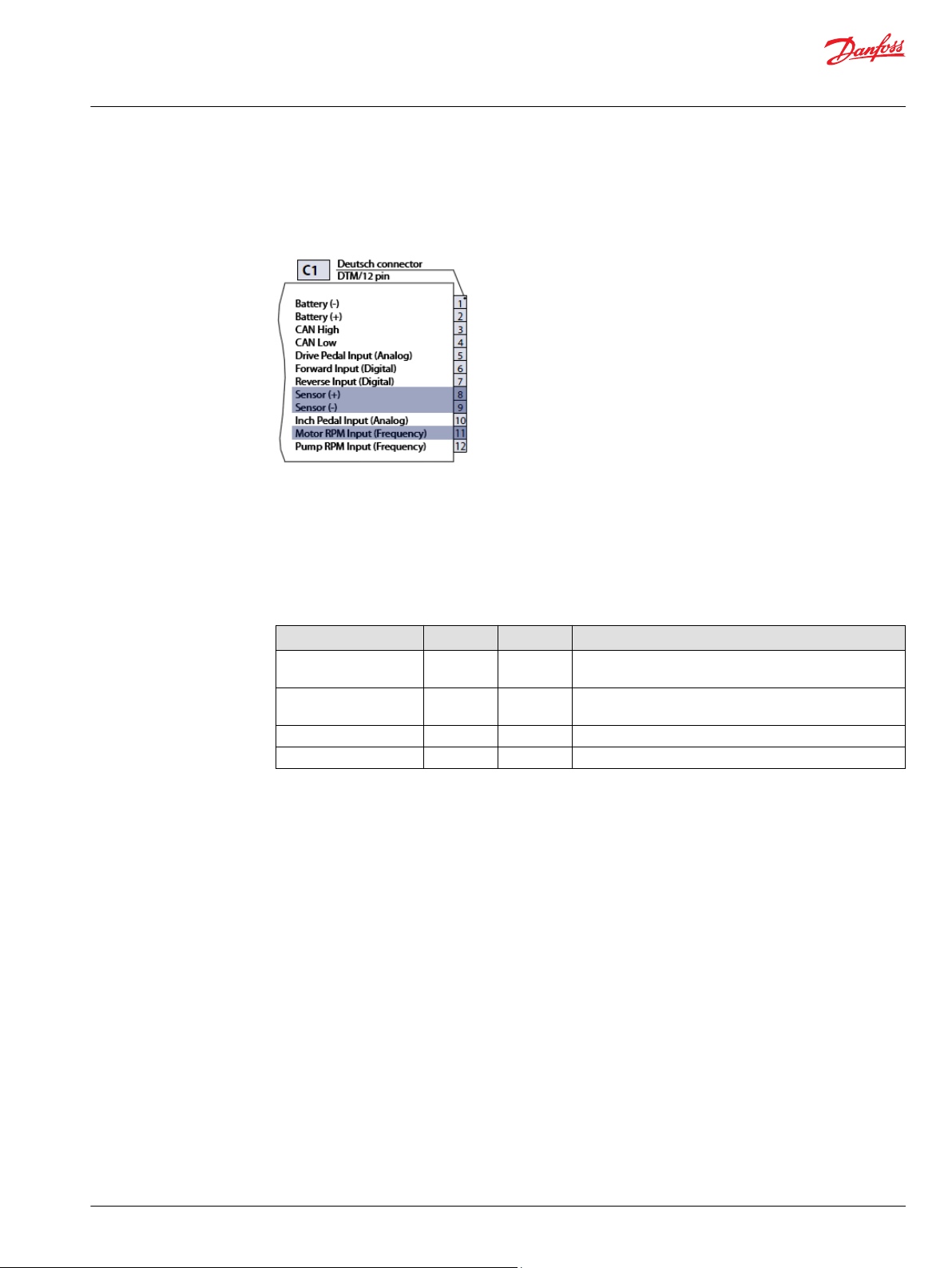
Input signals: Motor speed sensor
A motor speed sensor signal can be read by the MC-024 and used to calculate vehicle speed utilizing the
configured final drive ratio. The calculated vehicle speed enables advanced functions such as constant
speed operation and maximum vehicle speed limitation.
C1:08-Sensor (+) – Sensor supply (+)
•
Supply for sensors within 4.88 to 5.12 V
‒
Max. output current is 200 mA.
‒
C1:09-Sensor (-) – Sensor supply (-) direct GROUND
•
C1:11-Motor RPM Input (Frequency) – Frequency input for hydrostatic motor (PPU sensor)
•
DC
Frequency Input (Motor RPM)
Parameter Min Max Note
Rising voltage threshold
(middle range)
Falling voltage threshold
(middle range)
Input Impedance 7.17 kΩ 7.37 kΩ 15 kΩ to sensor supply / 13.5 kΩ to GND
Frequency range 0 Hz 10 000 Hz In steps of 1 Hz
2.92 V
1.02 V
4.12 V
DC
2.75 V
DC
The frequency input is guaranteed to be read as high if the
DC
voltage is greater than 4.12 V
The frequency input is guaranteed to be read as low if the
DC
voltage is less than 1.02 V
DC
DC
Mating connectors are available from Danfoss. For details see Mating Connectors on page 26.
For electrical details, please refer to the Technical Information PLUS+1 Controller Family, 520L0719.
©
Danfoss | Aug 2016 L1120636 | 0202 | 21
Page 22

Technical Information
Automotive on PLUS+1® for MC-024
Technical Specifications
Output signals: Pump displacement control
Displacement control for pumps with a Non-Feedback Proportional Electric (NFPE) or Electrical
Displacement Control (EDC). The pump command can be defined by the profile curve which can be
dependent on the engine speed (Automotive Mode, Creep-Automotive Mode) or the drive pedal (NonAutomotive mode).
C2:03-Pump displacement control forward – Proportional output (+) for the pump displacement
•
control
PWM Signal from battery Supply (12/24V)
‒
C2:04-Pump displacement control reverse – Proportional output (+) for the pump displacement
•
control
PWM Signal from battery Supply (12/24V)
‒
PWM Output
Parameter Min Max
Proportional current 10 mA 3000 mA
PWM frequency 33 Hz 200 Hz
Output voltage – Supply
Mating connectors are available from Danfoss. For details see Mating Connectors on page 26.
For electrical details, please refer to the Technical Information PLUS+1 Controller Family, 520L0719.
22 | © Danfoss | Aug 2016 L1120636 | 0202
Page 23

Technical Information
Automotive on PLUS+1® for MC-024
Technical Specifications
Output signals: Motor displacement and Brake Pressure Defeat (BPD) control
Variable displacement and 2-Position motors can be controlled directly. The output signal may be
controlled by pump (engine) speed or drive pedal position.
For vehicle braking conditions a Brake Pressure Defeat (BPD) valve can be controlled dependent on the
driving direction.
C2:07-Motor PROP/PCOR Driver – Proportional output (+) for the Pressure Control OverRide or
•
Proportional motor valve
PWM Signal from battery Supply (12/24V)
‒
C2:08-Motor BPD Driver – Digital output for the Brake Pressure Defeat valve
•
Switched to battery Supply (12/24V)
‒
Digital Output
Parameter Min Max
Output current 0 mA 3000 mA
Output voltage – Supply
Mating connectors are available from Danfoss. For details see Mating Connectors on page 26.
For electrical details, please refer to the Technical Information PLUS+1 Controller Family, 520L0719.
©
Danfoss | Aug 2016 L1120636 | 0202 | 23
Page 24

Technical Information
Automotive on PLUS+1® for MC-024
Technical Specifications
Output signals: Digital outputs 1, 2, 3, 4
C2:05-Output 1 Switched to battery (+) supply
•
C2:06-Output 2 Switched to battery (+) supply
•
C2:09-Output 3 Switched to battery (+) supply
•
C2:10-Output 4 Switched to battery (+) supply
•
The digital outputs 1, 2, 3, 4 can be used as single outputs (open loop - switch to battery supply).
The outputs can be configured individually to operate as:
Brake light,
•
Vehicle speed dependent signal
•
Retarder control (engine speed dependent output)
•
Status (Fault) LED
•
Park brake
•
FNR in forward
•
FNR in reverse
•
Reverse motion
•
Reverse LED
•
Digital Output
Parameter Min Max
Output current 0 mA 3000 mA
Output voltage – Supply
Mating connectors are available from Danfoss. For details see Mating Connectors on page 26.
For electrical details, please refer to the Technical Information PLUS+1 Controller Family, 520L0719.
24 | © Danfoss | Aug 2016 L1120636 | 0202
Page 25

Technical Information
Automotive on PLUS+1® for MC-024
Technical Specifications
CAN Communication: Input and Output signals
CAN communication is possible via the CAN connector. The physical (hardware) layer operates using the
CAN 2.0B specification for communication with either the PLUS+1 Service Tool or other external devices.
The J1939 protocol is enabled for communicating with other external devices.
C1:03-CAN High – Communication connection for CAN high line
•
C1:04-CAN Low – Communication connection for CAN low line
•
CAN Communication
Parameter Max
CAN Baudrate, physical layer per ISO11898-2; high speed 250 kBaud
Mating connectors are available from Danfoss. For details see Mating Connectors on page 26.
For electrical details, please refer to the Technical Information PLUS+1 Controller Family - 520L0719.
©
Danfoss | Aug 2016 L1120636 | 0202 | 25
Page 26

P301 353
Deutsch connector
DTM/12 pin
Battery (-) 1
Battery (+)
2
CAN High 3
CAN Low 4
Drive Pedal Input (Analog) 5
Forward Input (Digital) 6
Reverse Input (Digital) 7
Sensor (+) 8
Sensor (-) 9
Inch Pedal Input (Analog) 10
Motor RPM Input (Frequency)
11
Pump RPM Input (Frequency)
12
C1
P301 354
C2
Deutsch connector
DTM/12 pin
Mode Swich A Input (Digital)
1
Mode Swich B Input (Digital) 2
PWM Pump C1 (+) 3
PWM Pump C2 (+) 4
Digital Output 1 (+) 5
Digital Output 2 (+) 6
PWM Motor Control 7
Motor BPD Driver 8
Digital Output 3 (+) 9
Digital Output 4 (+) 10
Battery (+) 11
Battery (+) 12
Technical Information
Automotive on PLUS+1® for MC-024
Technical Specifications
Mating Connectors
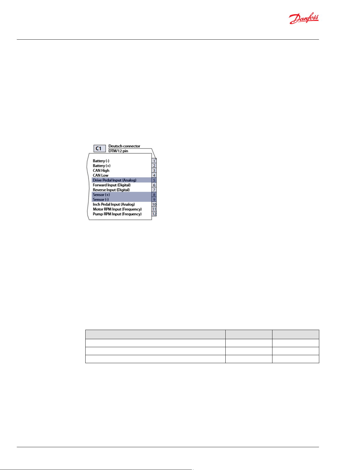
Customer connector: 1, 2 (C1, C2)
There are two available kits, differentiated by customer wire diameter, containing both C1 and C2 mating
connectors.
Customer connector 1 (C1) and 2 (C2)
Name Lead wire diameter Material No.
Assembly Bag with 2 DEUTSCH Connectors DTM06 12-SOCKET
Black/Grey and gold plated pins
Assembly Bag with 2 DEUTSCH Connectors DTM06 12-SOCKET
Black/Grey and gold plated pins (recommended)
0.5-1.0 mm2 / (16-20 AWG) 10102023
0.2-0.5 mm2 / (20-24 AWG) 10100945
26 | © Danfoss | Aug 2016 L1120636 | 0202
Page 27

1
2
3
4
5
6
7
8
9
10
11
12
DEUTSCH connector
DTM
/12 pin
Battery (-)
Battery (+)
CAN High
CAN Low
Analog Input 2
Digital Input 1
Digital Input 2
Sensor (+)
Sensor (-)
Analog Input 1
PPU Input 1
PPU Input 2
C1
120Ω
CAN Low
Female D-SUB connector
9 pin
CAN bus
4
1
6
8
2
3
5
7
9
CAN High
Ground
Shield
Power Supply (+)
nc
nc
nc
nc
Batt.
12
/24V
DC
+
-
F
1
A
P301 371
Technical Information
Automotive on PLUS+1® for MC-024
Technical Specifications
CAN Bus adapter cable
The additional Adapter Cable H1P AC CAN Guide, Material number: 11153051 is required to connect
the CG150 CAN USB Gateway with the Automotive Control (MC24).
The pigtail cable transitions from Deutsch to DSUB connector and contains terminating resistors to
enable CAN communication.
Bill of material:
CAN Deutsch Connector DTM06 3-12S; Material No. 10102023
•
9 pin female D-SUB Connector with housing
•
120 Ω resistor ¼W ± 5% or better
•
1 m cable 3 wire, diameter 0.2 to 1.0 mm² (0.5 mm² recommended)
•
AC Electrical Data & Characteristics
If using a cable longer than 1 m, a shielded cable is required. For further information see the J1939
specification.
For electrical details, please refer to the Technical Information PLUS+1 Controller Family - 520L0719
Supply characteristics
Parameter Min Max
Battery supply current
Recommended fuse size
Permanent supply voltage range
Rated 12 V range
Rated 24 V range
Permanent reverse voltage protection
Sensor supply voltage range (internal)
Sensor supply current
*
max 200 mA for all sensors together.
*
*
- 18 A
- 20 A
9 V
DC
9 V
DC
18 V
DC
- -36 V
4.88 V
DC
36 V
16 V
32 V
5.12 V
DC
DC
DC
DC
- 200 mA
DC
©
Danfoss | Aug 2016 L1120636 | 0202 | 27
Page 28

Technical Information
Automotive on PLUS+1® for MC-024
Technical Specifications
I/O characteristics
Digital inputs
Parameter Min Max
Rising voltage threshold
Falling voltage threshold
Input Impedance 13.9 kΩ 15.5 kΩ
1)
A digital input is guaranteed to be read as high if the voltage is greater than 4.15 VDC.
2)
A digital input is guaranteed to be read as low if the voltage is less than 1.01 VDC.
Analog inputs
Parameter Min Max
Input voltage range 0.08 V
Precision 1.28 mV
Input Impedance 206 kΩ 236 kΩ
Frequency Input (Motor RPM)
Parameter Min Max Note
Rising voltage threshold
(middle range)
Falling voltage threshold
(middle range)
Input Impedance 7.17 kΩ 7.37 kΩ 15 kΩ to sensor supply / 13.5 kΩ to GND
Frequency range 0 Hz 10 000 Hz In steps of 1 Hz
1)
2)
2.92 V
1.02 V
2.80 V
DC
1.01 V
DC
DC
4.12 V
DC
2.75 V
DC
The frequency input is guaranteed to be read as high if the
DC
voltage is greater than 4.12 V
The frequency input is guaranteed to be read as low if the
DC
voltage is less than 1.02 V
DC
DC
4.15 V
2.77 V
5.26 V
DC
DC
DC
DC
PWM Output
Parameter Min Max
Proportional current 10 mA 3000 mA
PWM frequency 33 Hz 200 Hz
Output voltage – Supply
Digital Output
Parameter Min Max
Output current 0 mA 3000 mA
Output voltage – Supply
28 | © Danfoss | Aug 2016 L1120636 | 0202
Page 29

Technical Information
Automotive on PLUS+1® for MC-024
Technical Specifications
Operating characteristics
Temperature range
Parameter Min Max
Application software download 0 °C 70 °C
Operation temperature -40 °C 70 °C
Storage temperature -40 °C 85 °C
CAN Communication
Parameter Max
CAN Baudrate, physical layer per ISO11898-2; high speed 250 kBaud
Environmental and Protection characteristics
Parameter Note
Short circuit All inputs and outputs will withstand continuous short circuit to all other leads.
EMC-Immunity (EMI) 100 v/m
EMC-Emission (RFI) 100 v/m
IP rating IP67 with mating connectors attached
Vibration IEC 600 68-2-64
Schock IEC 600 68-2-27 test Ea
When the short circuit is removed the unit returns to normal function.
©
Danfoss | Aug 2016 L1120636 | 0202 | 29
Page 30

Technical Information
Automotive on PLUS+1® for MC-024
30 | © Danfoss | Aug 2016 L1120636 | 0202
Page 31

Technical Information
Automotive on PLUS+1® for MC-024
©
Danfoss | Aug 2016 L1120636 | 0202 | 31
Page 32

Danfoss
Power Solutions GmbH & Co. OHG
Krokamp 35
D-24539 Neumünster, Germany
Phone: +49 4321 871 0
Danfoss
Power Solutions ApS
Nordborgvej 81
DK-6430 Nordborg, Denmark
Phone: +45 7488 2222
Danfoss
Power Solutions (US) Company
2800 East 13th Street
Ames, IA 50010, USA
Phone: +1 515 239 6000
Danfoss
Power Solutions Trading
(Shanghai) Co., Ltd.
Building #22, No. 1000 Jin Hai Rd
Jin Qiao, Pudong New District
Shanghai, China 201206
Phone: +86 21 3418 5200
Products we offer:
Comatrol
www.comatrol.com
Schwarzmüller-Inverter
www.schwarzmuellerinverter.com
Turolla
www.turollaocg.com
Hydro-Gear
www.hydro-gear.com
Daikin-Sauer-Danfoss
www.daikin-sauer-danfoss.com
Bent Axis Motors
•
Closed Circuit Axial Piston
•
Pumps and Motors
Displays
•
Electrohydraulic Power
•
Steering
Electrohydraulics
•
Hydraulic Power Steering
•
Integrated Systems
•
Joysticks and Control
•
Handles
Microcontrollers and
•
Software
Open Circuit Axial Piston
•
Pumps
Orbital Motors
•
PLUS+1® GUIDE
•
Proportional Valves
•
Sensors
•
Steering
•
Transit Mixer Drives
•
Danfoss Power Solutions is a global manufacturer and supplier of high-quality hydraulic and
electronic components. We specialize in providing state-of-the-art technology and solutions
that excel in the harsh operating conditions of the mobile off-highway market. Building on
our extensive applications expertise, we work closely with our customers to ensure
exceptional performance for a broad range of off-highway vehicles.
We help OEMs around the world speed up system development, reduce costs and bring
vehicles to market faster.
Danfoss – Your Strongest Partner in Mobile Hydraulics.
Go to www.powersolutions.danfoss.com for further product information.
Wherever off-highway vehicles are at work, so is Danfoss. We offer expert worldwide support
for our customers, ensuring the best possible solutions for outstanding performance. And
with an extensive network of Global Service Partners, we also provide comprehensive global
service for all of our components.
Please contact the Danfoss Power Solution representative nearest you.
Local address:
Danfoss can accept no responsibility for possible errors in catalogues, brochures and other printed material. Danfoss reserves the right to alter its products without notice. This also applies to products
already on order provided that such alterations can be made without changes being necessary in specifications already agreed.
All trademarks in this material are property of the respective companies. Danfoss and the Danfoss logotype are trademarks of Danfoss A/S. All rights reserved.
©
Danfoss | Aug 2016 L1120636 | 0202
 Loading...