

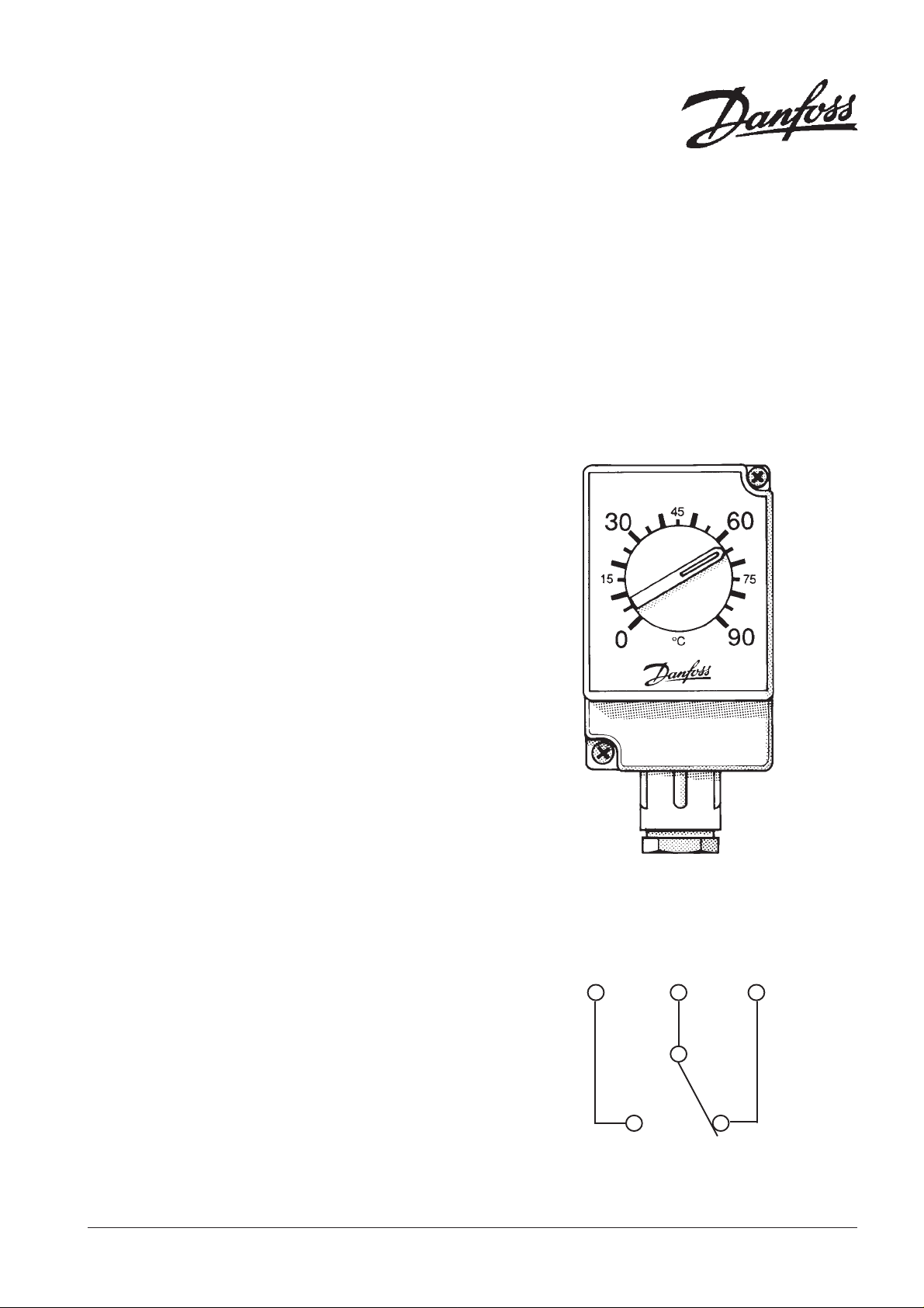
ATP
Pipe Thermostat
INSTALLATION INSTRUCTIONS
TECHNICAL SPECIFICATION
Temperature Range : 0 - 90°C
Switching Differential : 4 - 8K
Voltage Rating : 220/240 Volts AC 50Hz
Current Rating : 15 (2.5) Amp.
Switching Action : SPDT
The unit must be installed by a competent electrician and the installation should conform to the current IEE Wiring Regulations.
An Earth connection is required.
A) APPLICATION
The ATP Pipe Thermostat is suitable for all applications
requiring a surface mounted (clamp-on) thermostat for
controlling temperature in the range of 0-90°C.
The thermostat is supplied complete with a spring fixing
strap for use with pipework from ½" to 2".
The wide temperature range of the ATP allows the
thermostat to be used across a wide range of applications
including frost protection.
The thermostat setting can be locked between
5-25°C and 65-85°C.
B) FIXING THE THERMOSTAT
1. Ensure that the pipe surface to which the thermostat is
to be clamped is clean and free from paint and rust.
Apply a small quantity of the contact paste supplied with
the thermostat to the pipe wall.
2. Place the thermostat on the pipe, securing one end of
the spring fixing strap to one of the fixing lugs on the
thermostat. Stretch the spring strap around the pipe and
clip over the un-used fixing lug on the thermostat.
It is important that the spring strap holds the thermostat
tightly to the pipe.
Cut off any surplus spring strap using a pair of side
cutting pliers.
3. Remove the thermostat cover, take the flexible cord
through the gland plate and terminate the the cores of
the flexible lead on the appropriate terminals on the
thermostat, noting that,
Terminals C - 1: Break on rise of temperature,
Terminals C - 2: Break on fall of temperature.
It is important that the product be earthed.
4. If the setting of the thermostat is to be left unlocked, the
cover can now be re-fitted and the thermostat set to the
desired value.
5. If the setting is to be locked proceed to C) on the
following page.
WIRING DETAIL
2C1
C - 1 : BREAK ON RISE
C - 2 : BREAK ON FALL
1
C) LOCKING THE THERMOSTAT SETTING
The thermostat setting can be locked at any of the
following settings.
5, 10, 15, 20 and 25°C - Lower range
65, 70, 75, 80 and 85°C - Upper range
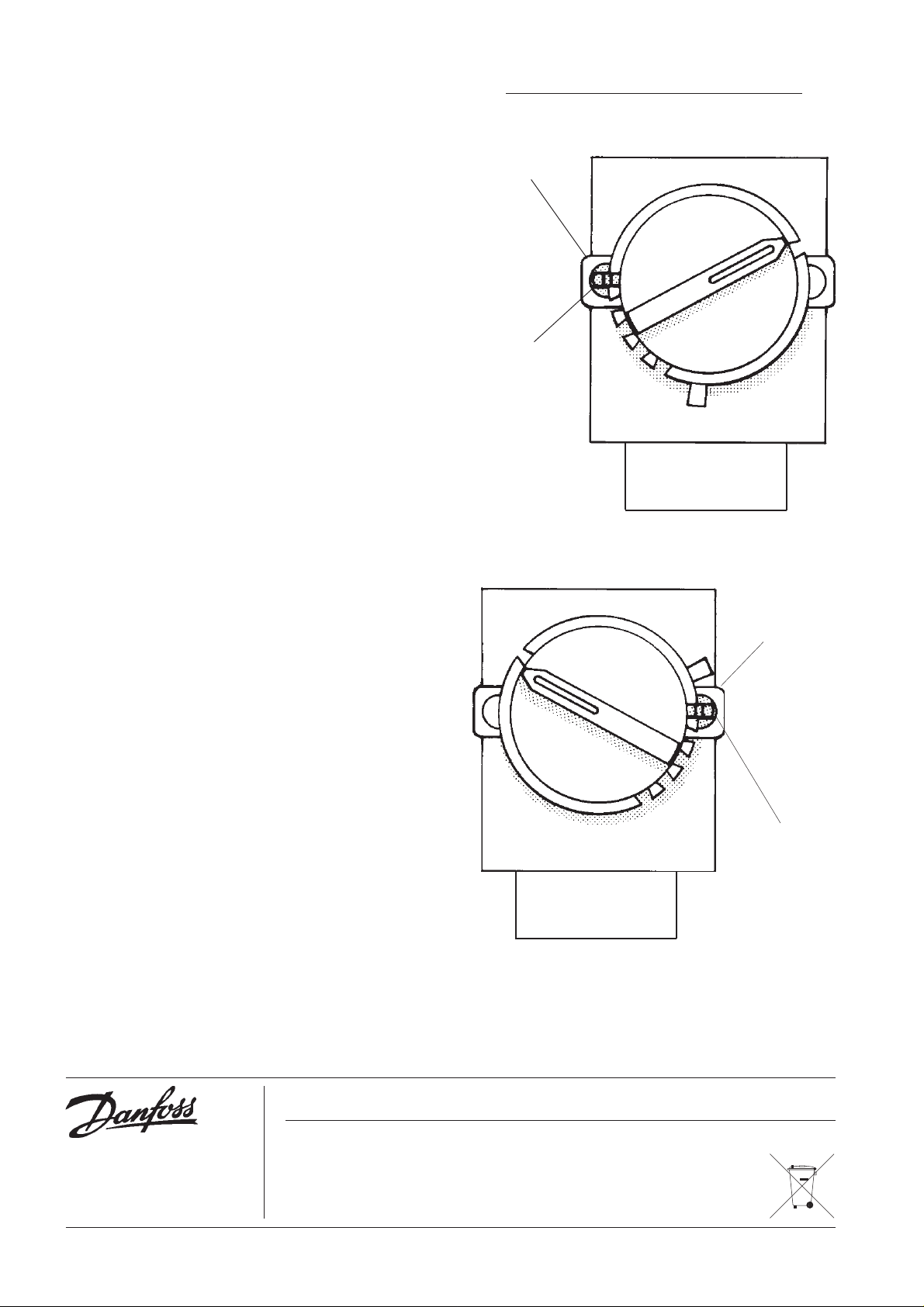
D) LOCKING THE THERMOSTAT SETTING
BETWEEN 65°C AND 85°C
1) Turn the thermostat knob to the temperature level at
which it is to be locked and remove the knob.
2) The thermostat is fitted with a knob locking screw
which on delivery may be parked in either the left or
right hand locking screw posts. The screw must be
positioned in the left hand locking screw post.
3) Turn the locking screw clockwise until the screw
bottoms on the thermostat case. Then turn the
locking screw counter-clockwise for three full turns
ensuring that the slot of the screw is vertical.
4) Replace the knob onto the thermostat shaft ensuring
that the locking screw aligns with the appropriate
cut-out in the knob base.
It is important for the locking screw and the cutout to align correctly. The slot in the locking
screw must be vertical.
5) Finally, replace the thermostat cover.
THERMOSTAT WITH COVER REMOVED
LOCKING
SCREW POST
KNOB
LOCKING
SCREW
LOCKING THE RANGE BETWEEN 65°C AND 85°C
E) LOCKING THE THERMOSTAT BETWEEN
5°C AND 25°C
1) Turn the thermostat knob to the temperature level at
which it is to be locked and remove the knob.
2) The thermostat is fitted with a knob locking screw,
which on delivery may be parked in either the left or
right hand locking screw post. For this operation it
must be located in the right hand post.
3) Turn the locking screw clockwise until the screw
bottoms on the thermostat case. Then turn the
locking screw counter-clockwise for three full turns
ensuring that the slot of the screw is vertical.
4) Replace the knob onto the thermostat shaft ensuring
that the locking screw aligns with the appropriate
cut-out in the knob base.
It is important for the locking screw and the cutout to align correctly. The slot in the locking
screw must be vertical.
5) Finally, replace the thermostat cover.
LOCKING
SCREW POST
KNOB
LOCKING
SCREW
LOCKING THE RANGE BETWEEN 5°C AND 25°C
Danfoss Randall can accept no responsibility for possible errors in catalogues, brochures and other printed material, and reserves the right to alter its products
without notice. This also applies to products already on order provided that such alterations can be made without subsequent changes being necessary in
specifications already agreed.
Danfoss Randall Ltd.,
Ampthill Road,
Bedford, MK42 9ER
Tel: 01234 364621 Fax: 01234 219705
Email: danfossrandall@danfoss.com
Website: www.danfoss-randall.co.uk
2
Part No. 2064 Issue.2 05/05
 Loading...