

Page 1
Datasheet
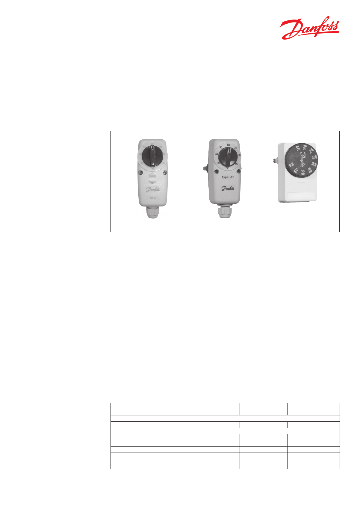
ATC, ATP and ATF
Clamp-On Thermostats
Features
ATC ATP ATF
ATC CLAMP-ON CYLINDER THERMOSTAT
The ATC clamp-on cylinder thermostat, which comes
complete with cylinder fi xing strap, is confi gured
specifi cally for the control of domestic hot water
cylinders.
The thermostat, which utilizes a bi-metallic strip
provides reliable and repeatable control, over a
wide range of temperatures (30-90°C).
The electrical contacts provide single pole double
throw operation making the thermostat suitable
for all types of motorised valves, including 3 port
mid-position types.
The thermostat, which is not pre-wired, incorporates
a sturdy mechanical cable gland which enhances
installation standards.
ATP CLAMP-ON PIPE THERMOSTAT
The ATP clamp-on pipe thermostat, which comes
with a pipe fi xing strap, is confi gured specifi cally
for use as a pipe thermostat, and is suitable for use
on pipes of up to 2” diameter (50mm).
The thermostat utilizes a bi-metallic strip. The metal
base of the thermostat makes direct contact with
the pipe. This type of construction provides accurate
and repeatable control.
Typical applications include:
• Pump run on thermostat.
• Safety thermostat for use in solid fuel heating
systems.
• Shunt pump control in oil fi red installation.
ATF CLAMP-ON FROST PROTECTION
THERMOSTAT
The ATF clamp-on pipe thermostat has a set range
of 10-90°C. The lower set point of 0°C makes the
thermostat particularly suited for frost protection
applications.
The ATF which utilises a vapour fi lled bellows, comes
with pipe fi xing strap. The ATF can be used in most
frost protection applications which require a pipe
thermostat including:
• 2nd stage operation in 2 stage frost protection
schemes.
• Frost protection termination function in systems
which utilise a room thermostat to initiate boiler
operation during periods of low internal room
temperature.
Specifi cations
ATC Cylinder Thermostat ATP Pipe Thermostat ATF Pipe Frost Thermostat
Temperature Rating (°C) 30-90 30-90 10-90
Voltage Rating of Switch 220/240 Vac, 50 Hz
Contact Rating of Switch 6(2.5)A 6(2)A 6(2)A
Switch Confi guration SPDT
Switching Diff erential (K) 6-10 6-10 8
Supplied with Fixing Strap for cylinders
Supplied with Fixing Strap for pipes (½ - 2")
Dimensions (mm) Wide
High
Deep
Part No. 374v11 03/10
40
120
58
40
120
58
40
85
58
1
Page 2
Datasheet
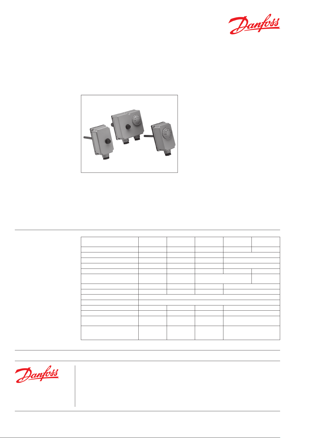
ITC, ITL and ITD
Immersion Thermostats
Features
ITL 100 Immersion Limit Thermostat
The ITL 100 immersion limit thermostat has an
insertion length of 100mm. This thermostat, which
is supplied with a ½" BSP/100mm pocket is suitable
for any application which demands an immersion
thermostat off ering manual re-set facility. The
thermostat is factory pre-set to 90°C and has SPDT
contacts.
ITD 100 Immersion Dual Control & Limit
Thermostat
The ITD 100 immersion thermostat incorporates
a separate limit and control function. The control
function set point can be varied between 0°C and
90°C. The limit function, which requires manual resetting after activation, is factory pre-set to 100°C.
ITC 100 Immersion Control Thermostat
The ITC 100 immersion thermostat has a 100mm
This thermostat is supplied with a ½" BSP/100mm
pocket.
insertion length. This thermostat, which is supplied
with a ½" BSP/100mm pocket, is suitable for the
control of any application which requires accurate
immersion sensing, for example in unvented hot
water systems. It which has an adjustment range of
0-90°C and has SPDT contacts making it suitable for
the control of all types of motorised valves.
Thermostats ITC Control ITC Control
Order Codes 099-1057 099-1058 099-1059 099-1061 099-1062
Control Function (Thermal Reset)
Limit Function (Manual Reset)
Dual Control and Limit Function
Temperature Range (°C) 0-90 0-90 0-90 0-90
Temperature Range (Limit) 90-110°C, Factory set to 90°C 90-110°C, Fac-
Switching Diff erential 4 ± 1K 4 ± 1K - 4 ± 1K
Switch Confi guration SPDT SPDT SPST SPDT (control), SPST (limit)
Switch Voltage Rating 220/240 Vac
Switch Current Rating 10 (2.5) A
Max. Ambient Temperature (Head) 65°C 65°C 80°C 80°C
Max. Medium Temperature 150°C 150°C 150°C 150°C
Supplied with ½” BSP(m) x 100mm
Pocket
Dimensions of
Thermostat Head (mm)
Wide
High
Deep
55
110
55.5
(tamperproof)
55
110
55.5
ITL Limit ITD Dual ITD Dual
tory set to 80°C
55
110
56.5
100
110
56.5
Danfoss can accept no responsibility for possible errors in catalogues, brochures, and other printed material. Danfoss reserves the right to alter its products without notice. This also applies to products already
on order provided that such alterations can be made without subsequential changes being necessary in specifications already agreed.
All trademarks in this material are propert y of the respective companies. Danfoss and the Danfoss logotype are trademarks of Danfoss A/S. All rights reserved.
Danfoss Ltd.
Ampthill Road
Bedford MK42 9ER
Tel: 01234 364621
Fax: 01234 219705
Email: ukheating@danfoss.com
Website: www.heating.danfoss.co.uk
2
Part No. 374v11 03/10
VDALA302
 Loading...