

Page 1
Data sheet ESBE ARA 600
Motor Actuator
Applications:
The ARA 600 series of motor actuators replaces
the Series 60 of 24V motor actuators mounted to
ESBE 3 way and 4 way rotary valves. Incorporated
into the redesign of the ARA motor actuators are
improvements in the mounting and operation
of the motor actuator resulting in a simpler and
quicker installation.
These redesigned direct mounted motor actuators
are capable of mounting to the new VRG styles of
3 & 4-way rotary valves. In addition, the ARA 600
series are also backward compatible to the older
MG and G series of valves.
The ARA 600 series is available in oating 3-point
with or without an auxiliary switch and proportional,
which cross over to the Series 60 actuators.
However there are additional varieties of actuators
to select from a 2-point actuator to di erent run
time options. These variety of selections provide
exibility in application selecting.
Features:
• Fewer parts and tools required
for installation
• Increased stabilization between actuator
and valve
• Backward compatible with MG and G series
of 3 & 4-way rotary valves
• Reduced pro le and size of motor actuator
• Easier mounting procedure
Ordering Information:
3-Point Floating Signal, 24VAC
Code No. Series Signal
193B160 0 ARA663
193B1601 ARA644
193B1602 ARA654 48 - -
193B160 3 ARA664 96 082F8974 62EM
Floating
3-point
Floating
3-point, w/
Aux. switch
Run Time
(90° @ 60Hz)
96 082F8972 62E
24 - -
Code No. Series
Replaces
VDKII202 © Danfoss 05/16
1
Page 2
Data sheet
ESBE ARA 600
Motor Actuator
Ordering Information
(Cont.):
2-Point Signal, 24VAC
Code No. Series Signal
193B160 4 ARA638
On/O w/
Aux. switch
193B160 5 ARA648 24 - -
Propotional Signal, 24V AC/DC
Code No. Series Signal
0-10VDC,
2-10VDC,
193B160 6 ARA639*
193B1607 ARA659
0-20mA,
4-20mA with
feedback
ability
0-10VDC,
2-10VDC,
0-20mA,
4-20mA
Run Time
(90° @ 60Hz)
12 - -
Run Time
(90° @ 60Hz)
15/30/60/120 - -
45/120 082F8973 62P
Code No. Series
Replaces
Replaces
Code No. Series
*Wire lead not connected
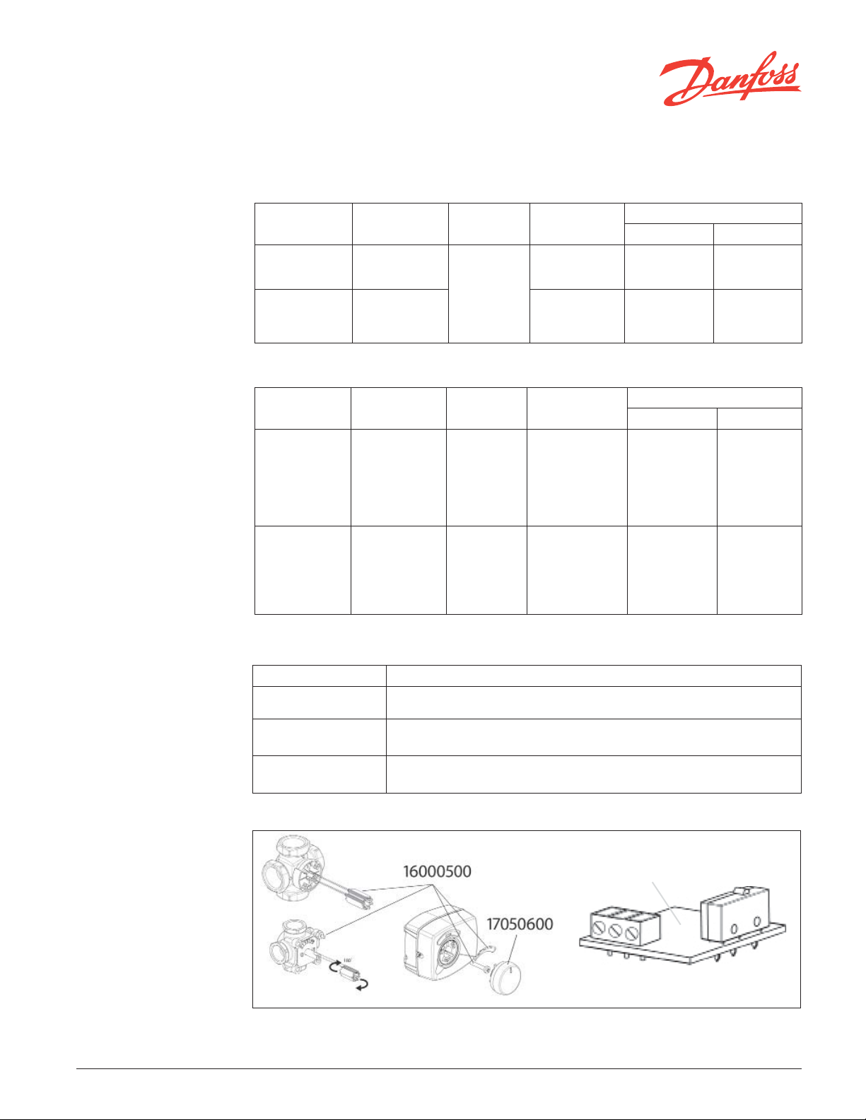
Accessories & Replacement Parts
Code No. Description
16000500 Assembly kit: drive sleeve, mounting stud scale and mounting screw
170 50 60 0 ARA motor actuator knob
16200700 Auxiliary end switch kit, includes end switch, cable and wiring plate cover
16200700
VDKII202 © Danfoss 05/16
2
Page 3

Data sheet
ESBE ARA 600
Motor Actuator
Applications:
4-way mixing valve application
3-way mixing valve application
3-way diverting valve application
3 & 4 Way VRG Valves:
3-Way Valve, Series 131
Code No. Connection Cv
193B150 0 ½” NPT 2.9
193B1501 ¾” NPT 4.7
193B1502 ¾” NPT 7.3
193B1503 1” NPT 7.3
193B150 4 1” NPT 11.7
193B1505 1-¼” NPT 18.7
193B150 6 1-½” NPT 29.3
193B1507 2” NPT 46.8
1
Cv value based on ow per a 1 psi pressure drop
through the valve
VDKII202 © Danfoss 05/16
4-Way Valve, Series 141
1
Code No. Connection Cv
193B1531 ¾” NPT 4.7
193B1532 ¾” NPT 7.3
193B1533 1” NPT 11.7
193B1534 1-¼” NPT 18.7
193B1535 1-½” NPT 29.3
193B1536 2” NPT 46.8
193B1537 ¾” Solder 2.9
193B1538 1” Solder 7.3
193B1539 1-¼” Solder 13.9
1
3
Page 4

Data sheet
ESBE ARA 600
Motor Actuator
Tec hni cal Speci cations:
3- Point 2- Point Proportional
ARA Series 663 / 644 / 654 / 664 638 / 648 639 / 659
Supply Voltage 24VAC +/- 10%, 50/60Hz
Power
Consumption
Rotation 90°
Torque 53.1 lbf.in (6Nm)
Mountable Valve
Size
Enclosure NEMA 1, IP 41
Ambient Temp.
Range
Weight 1 lb (0.4 kg)
Run Time (sec)
Control Signal -
Output signal -
Auxiliary Switch
Max 2A, adjustable cam position (663 actuator
1/2” to 2” ESBE rotary mixing valves, Series MG, G and VRG
663 96 sec
644 24 sec 639 15/30/60/120
654 48 sec
664 96 sec
does not have Aux. switch)
2VA
(for 638 mountable on sizes 1/2” to 1-1/4”)
24VAC +/- 10%,
638
648
23 to 131°F (-5 to 55°C)
638 12 sec
648 24 sec 659 45/120
50/60Hz
26.6 lbf.in
(3Nm)
53.1 lbf.in
(6Nm)
24VAC/DC +/- 10%,
AC 11VA 8VA
DC 6VA 4VA
53.1 lbf.in (6 Nm)
0-10V, 2-10V, 0-20mA,
4-20mA/ 60, 60 or 120 sec.
Proportional analogue
signal (only for ARA369)
50/60Hz
639 659
@ 60 Hz
Optional
Mounting & Installation:
4
The actuator should be mounted with the ESBE rotary valve stem in either a horizontal position or
pointing upwards. The actuator should not be installed in a downward orientation to reduce the possible
contact of water with the actuator. Included with the actuator is the mounting hardware necessary to
mount the electric motor actuator to an ESBE rotary mixing valves; MG, G, and VRG series.
Orientation
With the white drive sleeve the ARA actuator can be installed on older MG and G series of valves and
also current VRG valves. The orientation of the drive sleeve determines the style of valve the actuator
will mount to.
VDKII202 © Danfoss 05/16
Mounting Drive Sleeve
Page 5

Data sheet
ESBE ARA 600
Motor Actuator
Manual Operation:
Electrical Wiring
ARA600 Series Actuators:
When placing the actuator in manual operation power should be turned o to the actuator. In the
event the actuator is powered and is left in a manual position, the result could lead to the internal
damage of the actuator.
To manually operate the ARA Series actuator, slightly pull out on the large indicator knob. With it
pulled out, rotate the knob to the left or right to manually operate the valve. To return the actuator to
automatic operation, rotate the knob to the position prior to manual operation and push the knob into
the actuator.
ARA 663
BLUE COM
BLCK CCW
BRWN CW
ARA 644/654/664
BLUE COM
BLCK CCW
BRWN CW
WHITE COM
RED NO
ORNGE NC
ARA 659
BLUE COM
BLCK SGNL
BRWN PWR
ARA 639
5
VDKII202 © Danfoss 05/16
Page 6

Data sheet
ESBE ARA 600
Motor Actuator
Proportional Settings:
Internal Components:
Dip switch setting for ARA639
Switch descriptions:
1&2) Rotation time
3&4) Proportional signal
5) N/A
6) Motor actuator rotation
7) Activated lter (ON) reduces signal interferences reducing actuator hunting
8) During power outage, ARA639 remembers last position and does not require
calibration cycle
1
2
1. Mount sleeve to valve
2. Slide actuator onto valve
Dip switch setting for ARA659
Switch descriptions
1&2) Rotation time
3&4) Proportional signal
4
3. Secure actuator with mounting screw
5
4. Apply indicator, based on rotation
3
5. Push knob onto actuator
Dimensions:
in (mm)
Danfoss can accept no responsibility for possible errors in printed materials and reserves the right to alter its products without notice.
All trademarks in this material are property of the respective companies. Danfoss and Danfoss logotype are trademarks of Danfoss A/S. All rights reserved.
Danfoss
Toronto, ON
Toll Free: 866-375-HVAC (4822)
Fax: 416.352.5981
www.heating.danfoss.us
6
VDKII202 © Danfoss 05/16
Danfoss
Baltimore, MD
Toll Free: 866-375-HVAC (4822)
Fax: 416.352.5981
www.heating.danfoss.us
 Loading...