


Instruction
Disassembling and assembling
APP S 5.1-9.0 / APP S 674 5.1-9.0
ro-solutions.com

Instruction | Disassembling and assembling APP S 5.1-9.0 / APP S 674 5.1-9.0
Table of Contents
1. Introduction
1. Introduction ....................................................................................................................................................................... 2
2. Disassembling the pump .............................................................................................................................................. 3
3. Assembling the pump .................................................................................................................................................... 7
4. Disassembling and assembling of the swash plate ...........................................................................................13
5. Disassembling and assembling of cylinder barrel and valve plate ..............................................................14
6. Disassembling and assembling of the ushing valve ......................................................................................15
7. How to replace the shaft seal.....................................................................................................................................15
8. Changing pistons ...........................................................................................................................................................16
8.1 Disassembling .................................................................................................................................................................16
8.2 Assembling .......................................................................................................................................................................18
9. Spare parts list APP S (674) 5.1-9.0 ...........................................................................................................................20
9.1 Exploded view APP S (674) 5.1-9.0 ...........................................................................................................................21
10. When should the pistons be replaced ....................................................................................................................22
This document covers the instructions for disassembling and assembling the axial piston pumps
APP S 5.1-9.0 / APP S 674 5.1-9.0
Important: It is essential that the pump is
serviced in conditions of absolute cleanliness.
For a better understanding of the pump, please
see the exploded view in item 9.
Note:
For disassembling and assembling it must be
possible to place the pump vertically with the
shaft pointing downwards. This can be done
with a distance block with a minimum height
of 50 mm.
Tools needed:
• 10 mm combination wrench
• 13 mm combination wrench
• Torque wrench
• 2 screwdrivers
• 1 press bush tool
• Adjustable pin wrench
• Distance block
Note:
This document covers dierent pump sizes.
Therefore the images shown in the instruction
may dier from your actual pump and parts,
however, the priciples of disassembling/
assembling will be the same.
© Danfoss | DCS (im) | 2021.02
180R9258 | AX073186502887en-000401 | 2

Instruction | Disassembling and assembling APP S 5.1-9.0 / APP S 674 5.1-9.0
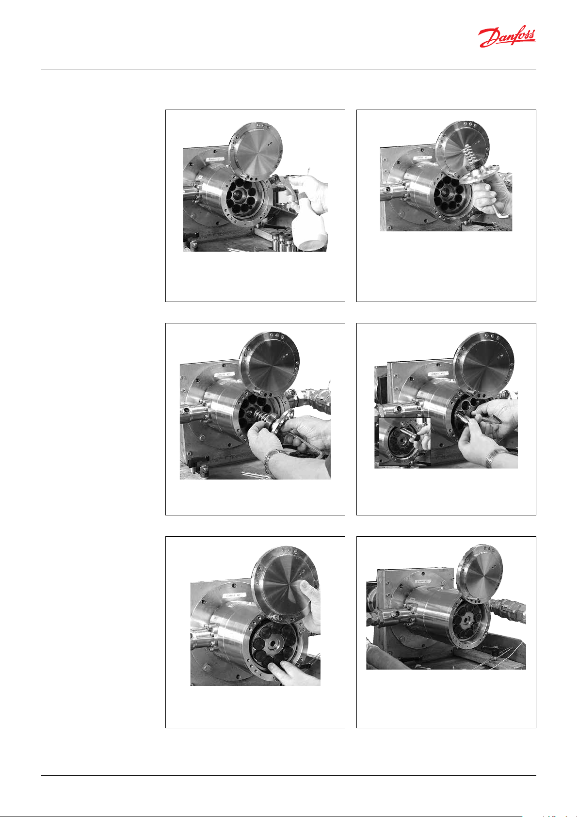
2. Disassembling the
pump
1. Disconnect the pump from the rest of the
system.
3. Carefully remove the stop bush ring and
the O-ring with a screwdriver.
2. Lubricate shaft with clean ltered water.
4. Using a 10 mm combination wrench,
unscrew the four bolts from shaft seal
cover.
WARNING!
While unscrewing the bolts with one
hand hold the shaft seal cover with the
other hand. This is done to ensure, the
cover does not pop out and damage the
ceramic ring.
© Danfoss | DCS (im) | 2021.02
5. Place two (!) bolts in threaded holes in the
shaft seal cover to remove it without
damaging the ceramic ring.
WARNING!
Be careful, the shaft has sharp edges.
180R9258 |AX073186502887en-000401 | 3

Instruction | Disassembling and assembling APP S 5.1-9.0 / APP S 674 5.1-9.0
6. Remove ceramic ring from ange by
carefully pushing it from the back of the
sealing ring.
7. Wet the shaft with clean water.
8. Through the inlet port lever the shaft seal
with a screw driver between shaft seal and
spring. Use one hand to pull the shaft seal up.
WARNING:
Be careful not to scratch the shaft.
10. Carefully remove the spring by levering it
with two screwdrivers.
9. Carefully remove the shaft seal and
distance ring; the shaft has a sharp edge.
11. Turn pump upside down and place pump
on a distance block. Make sure there is
enough free space for the shaft beneath
the housing.
© Danfoss | DCS (im) | 2021.02
180R9258 | AX073186502887en-000401 | 4

Instruction | Disassembling and assembling APP S 5.1-9.0 / APP S 674 5.1-9.0
12. Using a 13 mm combination wrench,
remove all the bolts on the mounting
ange except the two shown in item 13.
13. Unscrew the remaining two bolts. Turn
each bolt one round at the time to make
sure that the ange is removed as straight
upward as possible.
14. Remove end ange.
16. Remove the pistons one by one. Be careful
not to scratch the pistons. Tilt the retainer
plate to horizontal position for easy
removal of pistons, if required.
WARNING:
Do not use any tools.
15. Swash plate must be placed so that its
surface is not scratched. For further
disassembling of swash plate, see page 13.
17. Remove the retainer plate.
© Danfoss | DCS (im) | 2021.02
180R9258 |AX073186502887en-000401 | 5
Instruction | Disassembling and assembling APP S 5.1-9.0 / APP S 674 5.1-9.0
19. Remove the retainer ball.
20. Pull the cylinder barrel straight upwards in
a continuous lift to ensure no damage of
house bearing. This can only be done if the
shaft seal is removed.
WARNING:
If the cylinder barrel is dropped or
lowered too fast into housing, the main
bearing/shaft bearing might be
damaged.
20. Remove the retainer guide and the spring.
21. Place cylinder barrel upside down. For
further disassembling of cylinder barrel
and valve plate see page 14.
© Danfoss | DCS (im) | 2021.02
22. Remove the port plate in the housing by
hand.
23. Remove, by hand, the pin.
Note: The following operation is only
necessary if O-ring on port ange is to be
changed.
180R9258 | AX073186502887en-000401 | 6

Instruction | Disassembling and assembling APP S 5.1-9.0 / APP S 674 5.1-9.0
24. Turn the pump upside down.
25. If necessary, remove the remaining screws
in port ange by using a 13 mm
combination wrench.
3. Assembling the pump
WARNING:
Do not use silicone when assembling the
pump. Do not reuse disassembled O-rings;
they might be damaged. Always use new
O-rings.
1. Lubrication:
• To prevent seizing-up, lubricate all
threads with PTFE lubrication type.
• O-rings inside pump may be lubricated
only with clean ltered water.
• O-rings for port ange, mounting ange
and ushing valve must be lubricated.
• It is important to lubricate ALL parts to
be assembled with clean ltered water
(Especially all PEEK parts).
Important:
It is essential that the pump is serviced in
conditions of absolute cleanliness. All parts
must be absolute clean before mounting.
2. Place the housing with a drain holes
pointing upwards and insert pin for
positioning the port ange on housing.
© Danfoss | DCS (im) | 2021.02
3. Mount O-ring on port ange and lubricate
with water.
4. Position port ange by aligning pin hole
over pin.
5. Carefully press the port ange downwards.
Do not squeeze the O-ring. If the O-ring is
damaged, the pump will leak.
180R9258 |AX073186502887en-000401 | 7

Instruction | Disassembling and assembling APP S 5.1-9.0 / APP S 674 5.1-9.0
6. Lubricate the treads with PTFE lubrication.
Insert screws on the port ange. Tighten
screws to a torque of 30 ± 3 Nm.
Guide pin
7. Turn pump upside down. Place a 10.5 mm
guide pin in port ange.
9. Ensure port plate is tted tightly against
the bottom.
Important: If valve plate is disassembled
from cylinder barrel, please see page 14
before continuing.
8. Lubricate and position port plate by using
the pin. Do not use force for this operation.
Distance block
10. Place the pump on a distance block. Make
sure, there is enough free space for the
shaft beneath the housing.
© Danfoss | DCS (im) | 2021.02
180R9258 | AX073186502887en-000401 | 8
Instruction | Disassembling and assembling APP S 5.1-9.0 / APP S 674 5.1-9.0
11. Carefully lower cylinder barrel into the
housing.
WARNING:
If cylinder barrel is dropped or lowered
too fast into housing, main bearing and
shaft bearing might be damaged.
Replacement can only be done at
Danfoss, Nordborg.
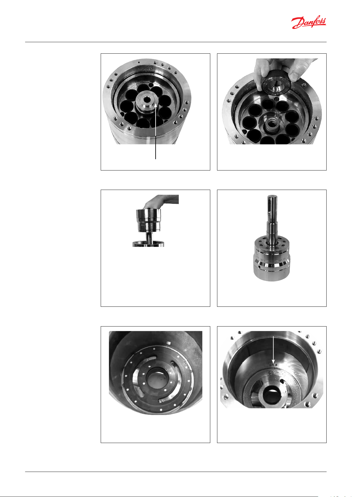
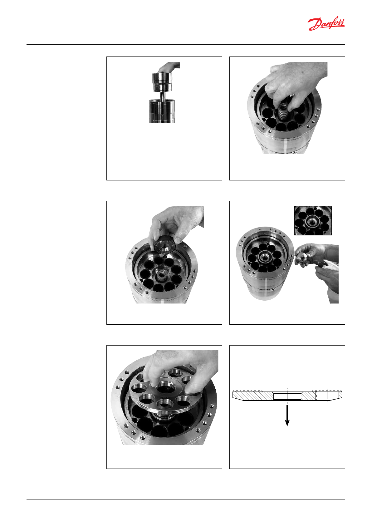
12. Place the spring in cylinder barrel and
lubricate liners inside cylinder barrel with
water.
14. Lubricate retainer guide and position the
retainer ball.13. Lubricate and position the retainer guide.
16. Ensure it is oriented correctly.15. Position the retainer plate.
© Danfoss | DCS (im) | 2021.02
180R9258 |AX073186502887en-000401 | 9

Instruction | Disassembling and assembling APP S 5.1-9.0 / APP S 674 5.1-9.0
17. Lubricate and position the pistons in the
retainer plate and cylinder barrel.
18. Lubricate the piston shoes. Tilt retainer
plate for easier placement of swash plate.
If the swash plate has been disassembled
from end ange, see page 13 for
assembling of swash plate. Remember to
place the pin in the housing.
19. Change and lubricate O-ring in end ange.
Position the end ange aligning pin hole
over the pin.
21. Screw in the rest of the bolts and tighten
all screws to the torque of 30 ± 3 Nm.
20. Lubricate and place two bolts in end
ange. Turn each bolt one round at a time
to ensure mounting ange is mounted as
straight downwards as possible. Be careful
not to squeeze the O-ring.
22. Lubricate and press new ceramic ring into
the shaft seal cover by using the press
bush tool.
WARNING:
Ensure that the face with rubber seal is
positioned against shoulder in shaft
seal ange.
© Danfoss | DCS (im) | 2021.02
180R9258 | AX073186502887en-000401 | 10

Instruction | Disassembling and assembling APP S 5.1-9.0 / APP S 674 5.1-9.0
23. Remove old O-ring and place the new one
on shaft seal cover.
24. Place pump upside down to get access to
shaft. Position the distance ring.
26. Mount new shaft seal with the carbon seal
face pointing upwards.25. Lubricate shaft with clean ltered water.
© Danfoss | DCS (im) | 2021.02
27. Press seal down and at the same time turn
the seal clockwise until spring stops at
distance ring. Spring against distance ring
180R9258 |AX073186502887en-000401 | 11

Instruction | Disassembling and assembling APP S 5.1-9.0 / APP S 674 5.1-9.0
28. Position the shaft seal cover on shaft. Be
careful not to damage the ceramic ring.
WARNING!
Be careful, the shaft has sharp edges.
29. Hold the cover down with one hand and
tighten the bolts with the torque
according to exploded view - page 17.
30. Lubricate the shaft with water before
mounting the stop bush.
32. Press stop bush in place by using the press
bush tool.
31. Mount O-ring and stop bush on shaft.
Ensure the gap with O-ring grove is
pointing in correct direction (towards
pump).
© Danfoss | DCS (im) | 2021.02
180R9258 | AX073186502887en-000401 | 12

Instruction | Disassembling and assembling APP S 5.1-9.0 / APP S 674 5.1-9.0
4. Disassembling and
assembling of the
swash plate
1. Unscrew centre bolt from swash plate and
remove the swash plate.
O-ring
2. Place two new pins in the end ange, if
needed. Change the O-ring in the end
ange. Remember to lubricate.
4. Lubricate centre bolt thread with a PTFE
lubricant type.3. Carefully align swash plate over pins.
6. Screw centre bolt into centre of swash
plate and tighten to 30 ±3 Nm. Finally
check the surface on the swash plate for
any marks or foreign particles.5. Position centre bolt.
© Danfoss | DCS (im) | 2021.02
180R9258 |AX073186502887en-000401 | 13

Instruction | Disassembling and assembling APP S 5.1-9.0 / APP S 674 5.1-9.0
5. Disassembling and
assembling of cylinder
barrel and valve plate
1. Push a screwdriwer into the hole between
cylinder barrel and valve plate. Carefully
push downward the screwdriver so that it
makes a gap between cylinder barrel and
valve plate. Use this gap to put in another
screwdriver and loosen the valve plate
from the cylinder barrel.
O-ring
Back-up ring
O-ring
Back-up ring
2. Remove the O-rings and backup rings on
valve plate. If they have been removed
they can not be reused.
3. Mount the new back-up rings on the valve
plate rst and then mount the O-rings.
5. Lower the valve plate upside down on the
cylinder barrel.
4. Lubricate the new O-rings/back-up rings
and the liners in the cylinder barrel with
clean ltred water.
6. Press by hand valve plate into cylinder
barrel.
Cylinder barrel is now ready for mounting.
© Danfoss | DCS (im) | 2021.02
180R9258 | AX073186502887en-000401 | 14

Instruction | Disassembling and assembling APP S 5.1-9.0 / APP S 674 5.1-9.0
6. Disassembling and
assembling of the
ushing valve
1. Unscrew the ushing valve
counterclockwise by using the pin wrench.
valve cone
3. It is important that if the spring is changed
it is located like on the picture. The end of
the spring must be against the shoulder of
the valve cone.
2. Remove the O-rings. If necessary, change
the valve cone, spring and plug.
4. Lubricate seals with clean ltered water
and lubricate thread with PTFE lubrication.
Screw it into the port ange. Tighten with
a torque of 30 Nm ±3 Nm.
7. How to replace the
shaft seal
© Danfoss | DCS (im) | 2021.02
Disassembling, please see Assembling, please see
Page 3 items 2 to 5 Page 10 item 19
Page 4 items 6 to 11 Page 11 items 20 to 25
Page 12 items 28 to 32
180R9258 |AX073186502887en-000401 | 15
Instruction | Disassembling and assembling APP S 5.1-9.0 / APP S 674 5.1-9.0
8. Changing pistons 8.1 Disassembling
To understand the pump design better, please
see the exploded view in item 9.
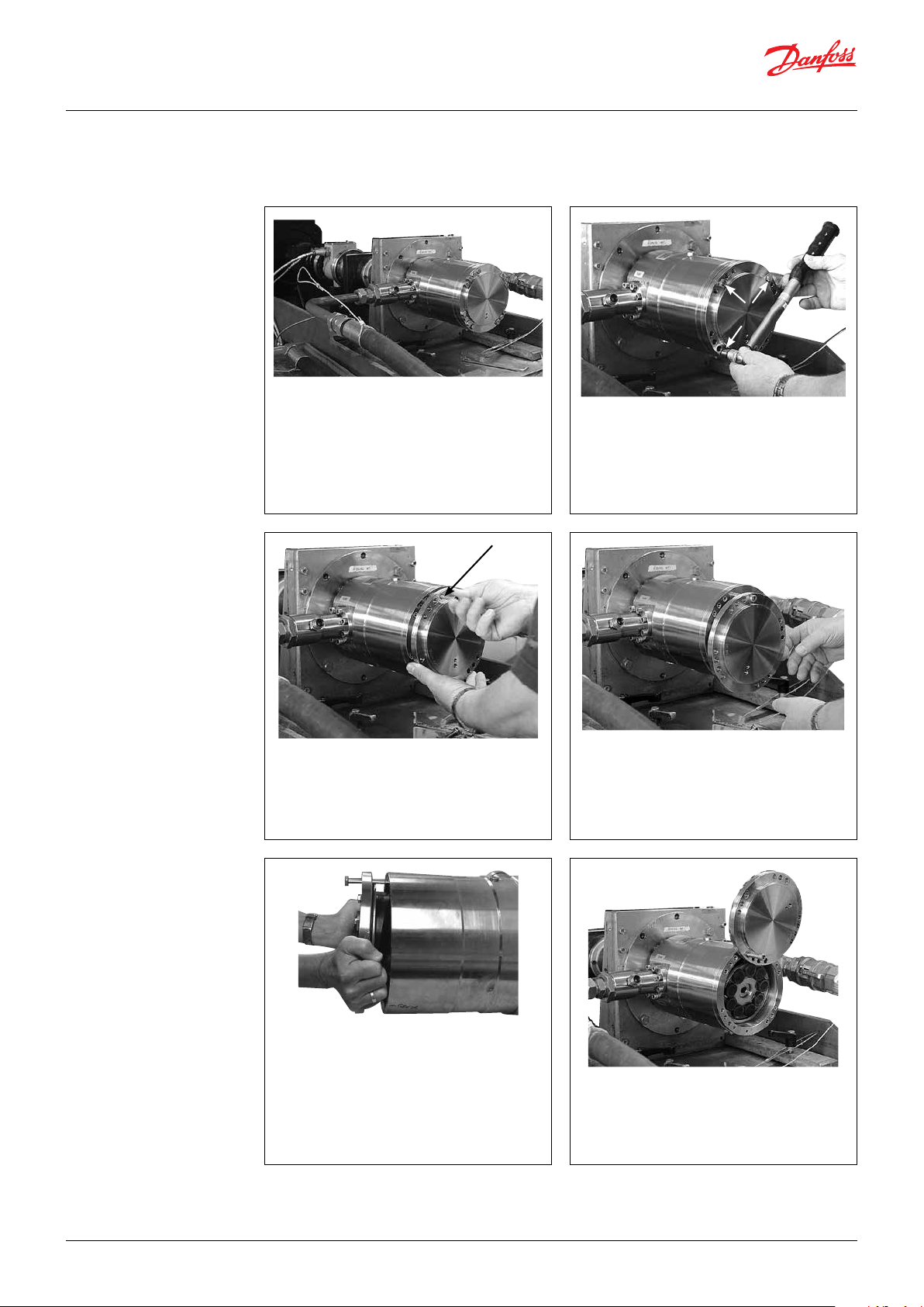
1. Disconnect the pump from the rest of the
system or close inlet valve.
2.
Loosen all screws on the pump except the
three screws as shown in the picture below.
Note: There is still water inside the pump.
3. A long M8 guide bolt can be mounted in
the top hole.
5. Remove the ange. The guide bolt must
remain mounted.
4. Unscrew the remaining three screws.
6. Carefully turn the ange and push it
backwards to make it rest on the housing
surface. Ensure not to scratch the swash
plate surface. The ange can also be
removed.
© Danfoss | DCS (im) | 2021.02
180R9258 | AX073186502887en-000401 | 16
Instruction | Disassembling and assembling APP S 5.1-9.0 / APP S 674 5.1-9.0
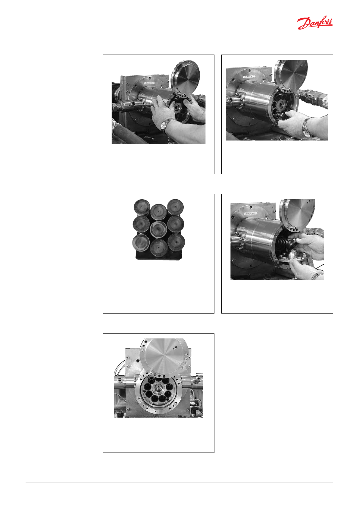
7. Adjust the retaining plate to be parallel to
the end ange.
9. WARNING:
Ensure that the piston shoes and the
piston surfaces are not damaged during
removal.
It is recommended to place the pistons
upside down on an even and clean base/
surface.
8. Carefully remove the pistons one by one.
10. Remove retainer plate, ball, guide and
spring.
© Danfoss | DCS (im) | 2021.02
12. Replace any worn parts.11. Inspect the piston liners.
180R9258 |AX073186502887en-000401 | 17
Instruction | Disassembling and assembling APP S 5.1-9.0 / APP S 674 5.1-9.0
8.2 Assembling
1. Ensure liner and end of cylinder barrel are
wetted.
2.
Place retainer plate, ball, guide and spring
on the allen key.
WARNING!
Ensure right assembling and side of
retainer plate.
3. Carefully place all parts in the cylinder
barrel.
5. Place the retainer plate in an odd angle
corresponding to the orientation of the
swash plate.
4. Insert the pistons one by one. At the same
time keep the retainer plate in place with
the other hand.
6. Tilt the ange and replace the ange
O-ring.
© Danfoss | DCS (im) | 2021.02
180R9258 | AX073186502887en-000401 | 18

Instruction | Disassembling and assembling APP S 5.1-9.0 / APP S 674 5.1-9.0
7. Turn the ange and gently push it into the
housing.
9. Remove the guide bolt and mount the
remaining bolts.
11. Connect the pump to the rest of the
system.
8. Mount two screws as shown below and
tighten them.
10. Cross tighten the bolts to a torque of
30 Nm ± 3 Nm.
12. Bleed the pump before starting it up.
© Danfoss | DCS (im) | 2021.02
180R9258 |AX073186502887en-000401 | 19
Instruction | Disassembling and assembling APP S 5.1-9.0 / APP S 674 5.1-9.0
9. Spare parts list APP S (674) 5.1-9.0
)
3.1 Material certicate not traceable
²
)
PMI rapport not available
³
Pos. Qt y. Designation Material
1 1 Housing Super Duplex/PEEK X X
2 2 Pin AIS I 316
3 4 Bleeding plug, G1/4” Super Duplex X
4 4 O-ring NBR X
5 14 Screw M8x25 AI SI 316 X
9 1 O-ring NBR X
11 1 End ange Super Duplex X X X
12 1 Lifting eye Duplex
31 1 Swash plate Super Duplex X X X X X X
32 1 Screw M8x20 Super Duplex X X X X X X
34 2 Pin Super Duplex X X
61 1 Complete cylinder barrel X
(1) Cylinder barrel Super Duplex X
(1) Shaft Super Duplex X
(9) Bushing PEEK
62 1 Spring Duplex X X
64 1 Retainer ball Super Duplex X X
65 1 Retainer plate Super Duplex X X
66 9 Piston Super Duplex/PEEK X X
67 1 Key AIS I 316 X
71 1 Retainer guide Super Duplex/PEEK X X
91 1 Por t plate Super Duplex/PEEK X
92 1 Complete valve plate X
(1) Valve plate Super Duplex X
(9) Valve shoes Super Duplex X
93 9 Back-up ring PTFE X
94 9 O-ring NBR X
121 1 Port ange Super Duplex/PEEK X X
122 1 O-ring NBR X
123 1 O-ring NBR X
124 1 Shaft seal Hastelloy C4 X X
125 1 Cover for shaf t seal Super Duplex X X
126 1 Pin Super Duplex X X
127 4 Screw M6 x 16 AISI 316 X
128 14 Screw M8 x 90 AISI 316 X
129 1 Stop bush Polypropylene X
130 1 O-ring FPM X
131 2
132 2 O-ring EPDM X
133 16 Screw M8x25 AISI 316 X
140 1 Bearing PEEK
142 1 Stop for shaft seal Super Duplex X
144 4 Tailstock screw M12x60 AISI 316 X
145 4 Check nut M12 AISI 316 X
146 1 Eye bolt M8 AISI 1015
148 1 O-ring NBR
151 1 O-ring FPM X X
152 1 Valve cone Super Duplex X X
153 1 Spring Hastelloy C276 X
154 1 Plug/guide Super Duplex X X X
155 1 O-ring NBR X X
Cover for port connection
Instruction X X X X X X X X X X X X
AIS I 316
Pressure Containing Parts,
3.1 Material Certicate
Available and Traceable
Metallic Process Wet ted Parts,
PMI Rapport Available
180B4261 Seal & screw set
APP S (674) 5.1-9.0
180B4243 Shaft seal set
APP S (674) 5.1-9.0
180B4244 Cylinder barrel set
APP S (674) 5.1-9.0
180B4245 Valve plate set
APP S (674) 5.1-9.0
180B4246 Retainer set
APP S (674) 5.1-9.0
180B4247 Piston set
APP S (674) 5.1-9.0
180B4262 Swash plate set
APP S (674) 5.1
180B4263 Swash plate set
APP S (674) 6.5
180B4264 Swash plate set
APP S (674) 7.2
180B4248 Swash plate set
APP S (674) 8.2
180B4249 Swash plate set
APP S (674) 9.0
2)
X X
3)
3)
X
180B4250 Flushing valve set
APP S (674) 5.1-9.0
X
© Danfoss | DCS (im) | 2021.02
180R9258 | AX073186502887en-000401 | 20
Instruction | Disassembling and assembling APP S 5.1-9.0 / APP S 674 5.1-9.0
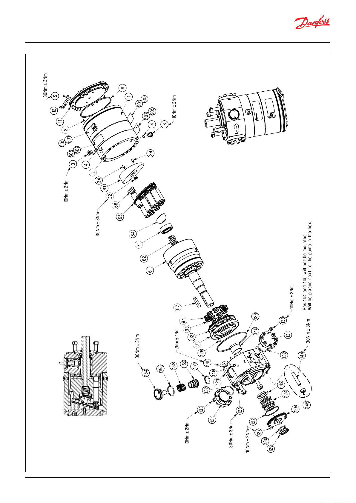
9.1 Exploded view
APP S (674) 5.1-9.0
© Danfoss | DCS (im) | 2021.02
180R9258 |AX073186502887en-000401 | 21
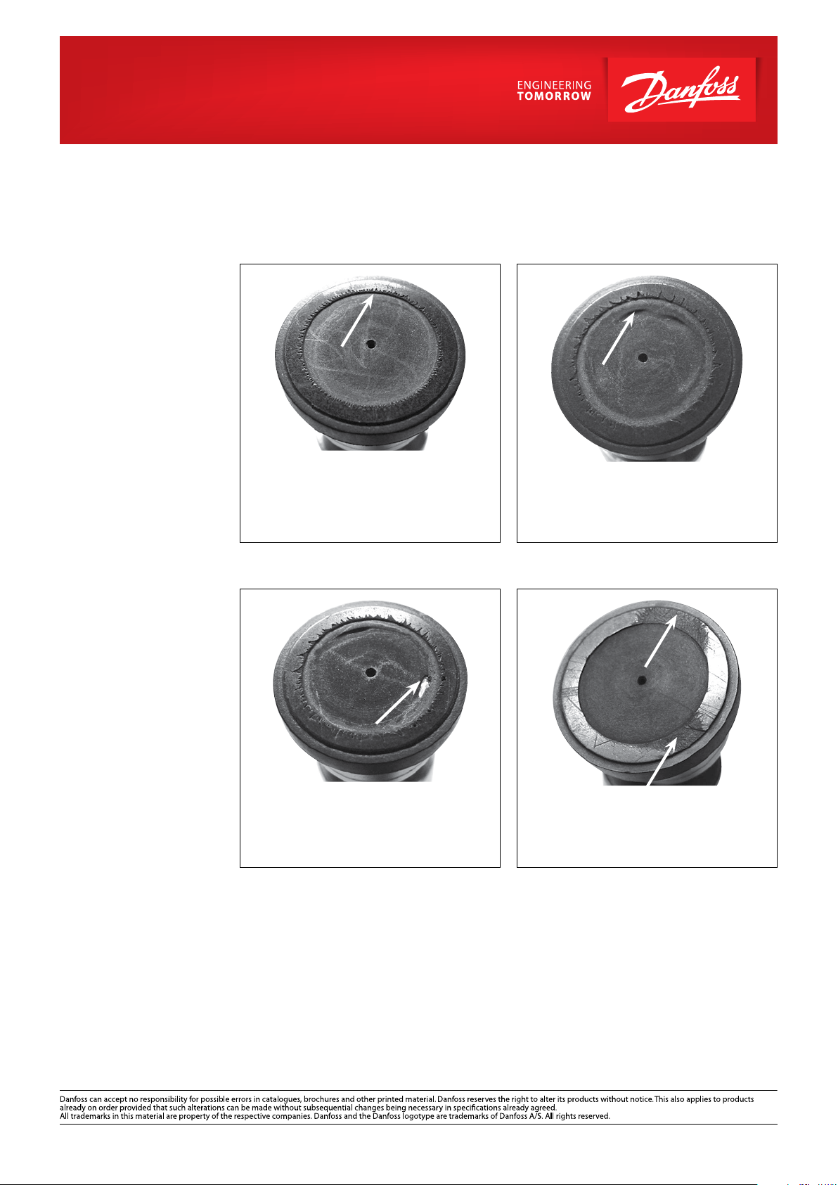
10. When should the pistons
be replaced
This section provides guidance on, how to
determine whether the parts of the pump are
worn and should be replaced. In case of doubt
- the pistons must be replaced. The pictures
below are meant as a guideline for evaluating
the wear of the sliding surface.
Note: If the pistons break down, the pump will
suer a disastrous breakdown.
1. Picture 1:
Cavitation of the piston shoes.|
New inspection is required in 3,000-4,000
hours.
3. Picture 3:
Cavitation of the piston shoes.
All pistons must be replaced within the
next 100-200 hours.
2. Picture 2:
Cavitation of the piston shoes.
All pistons must be replaced within the
next 500-1,000 hours.
4. Picture 4:
Abrasive wear of the piston shoes.
All pistons must be replaced immediately.
Danfoss A/S
High Pressure Pumps
DK-6430 Nordborg
Denmark
© Danfoss | DCS (im) | 2021.02
180R9258 | AX073186502887en-000401 | 22
 Loading...