

Page 1
Instruction
APP S / APP S 674 pumps
APP S 2.0-3.5 / APP S 674 2.0-3.5 pumps
Disassembling and assembling
ro-solutions.com
Page 2
Instruction Disassembling and assembling APP S 2.0-3.5 / APP S 674 2.0-3.5
Table of Contents 1. Disassembling the pump .............................................................................................................................................. 3
2. Assembling the pump.................................................................................................................................................... 7
3. Disassembling and assembling of the swash plate ........................................................................................ 13
4. Disassembling and assembling of cylinder barrel and valve plate ........................................................... 14
5. Disassembling and assembling of the ushing valve ...................................................................................... 15
6. How to replace the shaft seal .................................................................................................................................... 15
7. Changing pistons ......................................................................................................................................................... 16
7.1 Disassembling .................................................................................................................................................................16
7.2 Assembling .......................................................................................................................................................................18
8. Spare parts list APP S 2.0-3.5 ...................................................................................................................................20
8.1 Explode view APP S 2.0-3.5 ........................................................................................................................................ 21
9. Spare parts list APP S 674 2.0-3.5 ........................................................................................................................... 22
9.1 Explode view APP S 674 2.0-3.5 ................................................................................................................................ 23
10. When should the pistons be replaced .................................................................................................................24
Introduction
NOTE: If the pump is disassembled within the warranty period, the pump is no longer covered
by the warranty.
This document covers the instructions for
disassembling and assembling the axial piston
pumps APP S 2.0-3.5 / APP S 674 2.0-3.5 pumps.
Important: It is essential that the pump is
serviced in conditions of absolute cleanliness.
Tools needed:
• 6 mm allen key
• 8 mm allen key
• Torque wrench
• 2 screwdrivers
• 1 press bush tool (part of seal kit)
• Distance block
For a better understanding of the pump, please
see the exploded view in section 7.
Note:
When disassembling and assembling it must
be possible to place the pump vertically with
the shaft pointing downwards. This can be
done with a distance block with a minimum
height of 50 mm.
Our CLP RO pumps have changed the name as listed below:
CLP674 050-058 RO: will now be called APP S 674 3.0-3.5
CLP 674 085-152 RO: will now be called APP S 674 5.1-9.0
CLP674 365-640 RO: will now be called APP S 674
This is ONLY a name change.
2
180R9281 | 521B1275 | DKCFN.PI.013.C5.02 | 07.2019
Page 3
Instruction Disassembling and assembling APP S 2.0-3.5 / APP S 674 2.0-3.5
1. Disassembling the
pump
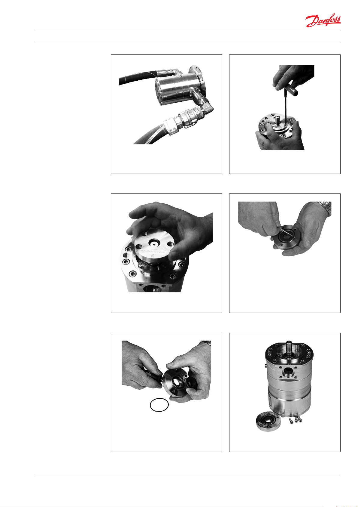
1. Disconnect the pump from the rest of the
system.
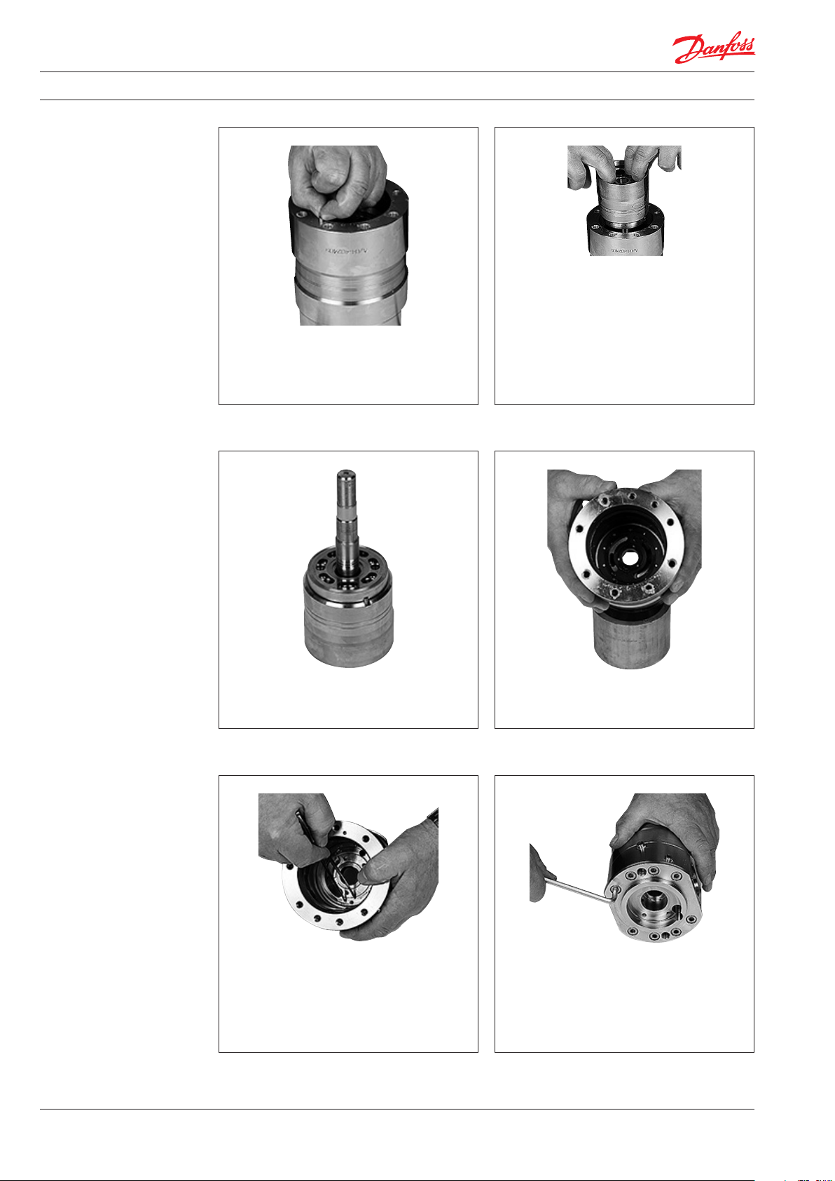
2. Using a 6 mm allen key, unscrew the 3
bolts from shaft seal cover.
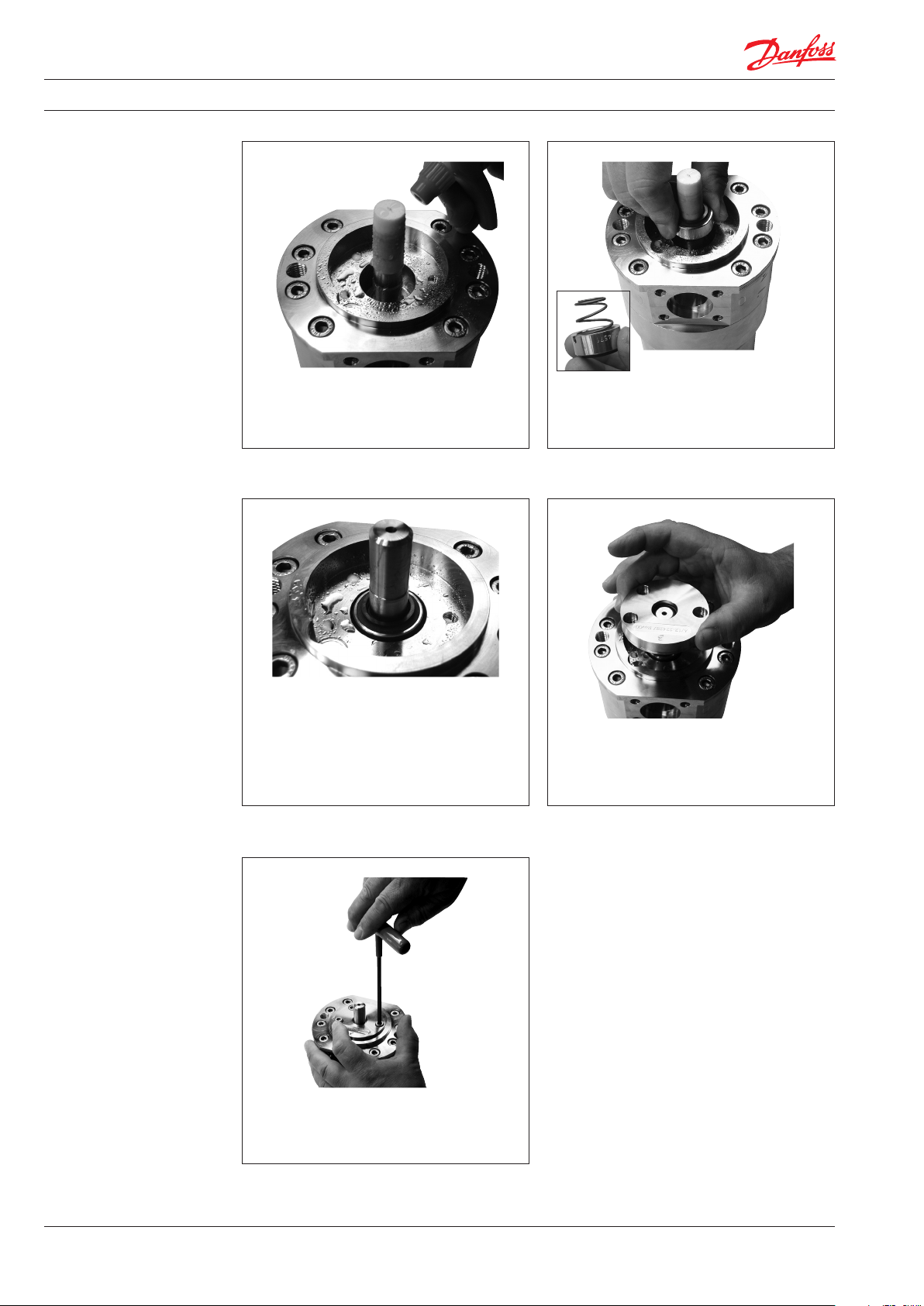
3. Remove shaft seal bushing. 4. Remove O-ring with a small screwdriver.
5. Remove ceramic ring from cover by
carefully pushing it from the back of the
sealing ring with a screwdriver.
180R9281 | 521B1275 | DKCFN.PI.013.C5.02 | 07.2019
6. Clean and then wet the shaft with clean
water.
3
Page 4
Instruction Disassembling and assembling APP S 2.0-3.5 / APP S 674 2.0-3.5
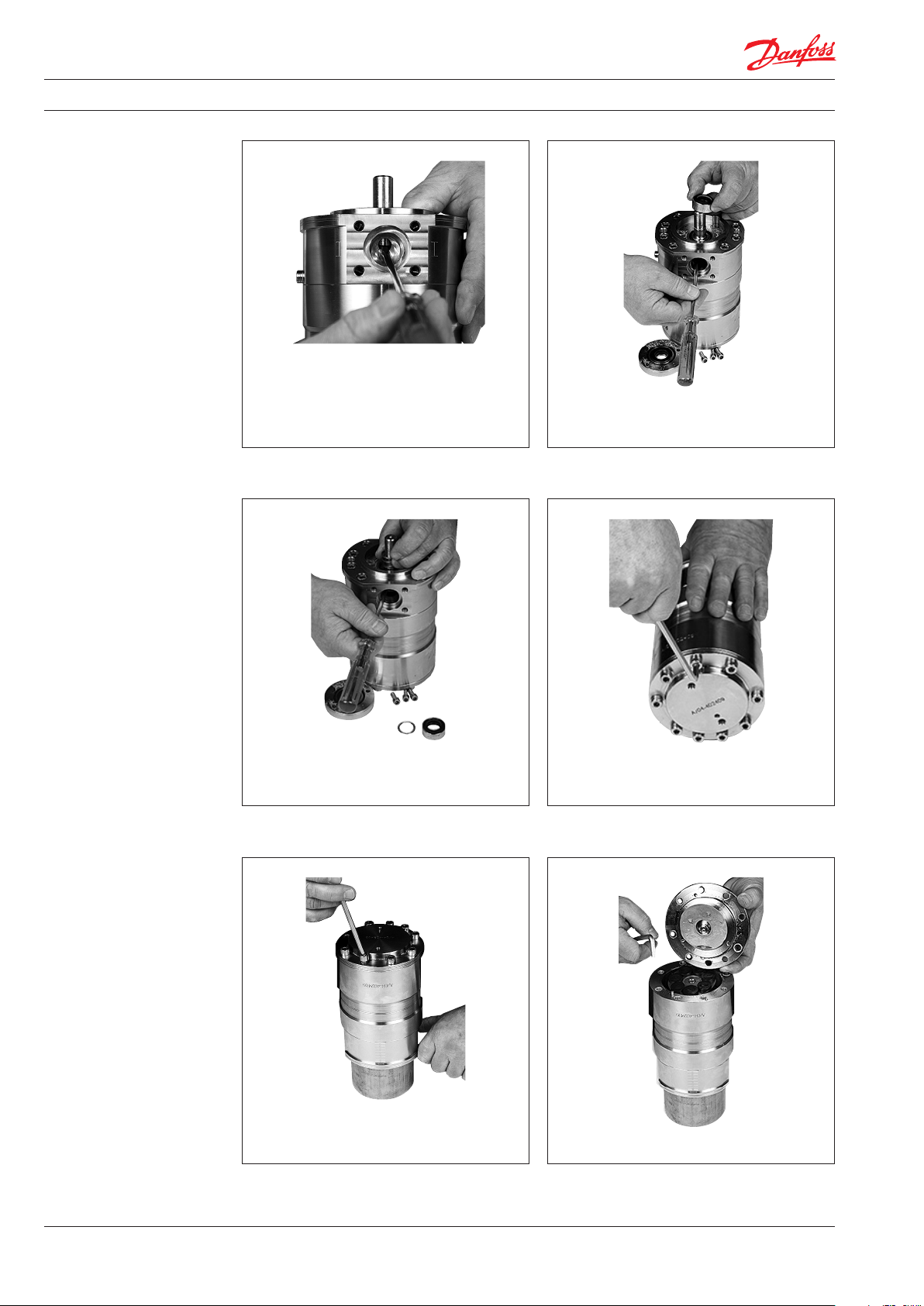
7. Through the inlet port lever the shaft seal
with a screw driver between shaft seal and
spring. Use one hand to pull the shaft seal up.
WARNING:
Be careful not to scratch the shaft.
8. Carefully remove the shaft seal and
distance ring.
9. Carefully remove the spring by lifting it
with a screwdriver and one hand to pull
the spring up.
11. Place pump on a distance block. Make
sure there is enough free space for the
shaft beneath the housing. Remove all bolts.
10. Using a 8 mm allen key, unscrew all bolts
on the end ange.
12. Remove end ange.
4
180R9281 | 521B1275 | DKCFN.PI.013.C5.02 | 07.2019
Page 5

Instruction Disassembling and assembling APP S 2.0-3.5 / APP S 674 2.0-3.5
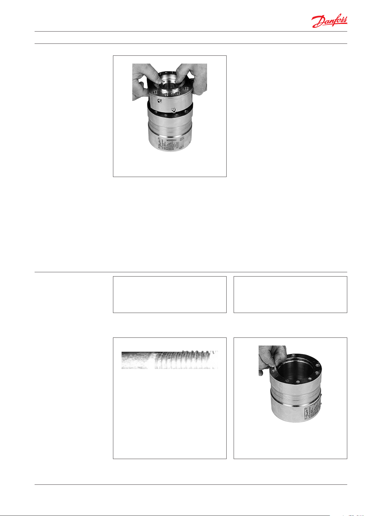
14. Remove 2 pistons. Be careful not to scratch
13. Swash plate must be placed so that its
surface is not scratched. For further
disassembling of swash plate, see page 14.
the pistons.
WARNING:
Do not use any tools.
15. Remove the retainer plate with the
remaining pistons. 16. Remove the retainer ball.
17. Remove the retainer guide and the spring.
180R9281 | 521B1275 | DKCFN.PI.013.C5.02 | 07.2019
5
Page 6
Instruction Disassembling and assembling APP S 2.0-3.5 / APP S 674 2.0-3.5
19. Pull the cylinder barrel straight upwards in
a continuous lift to ensure no damage of
house bearing. This can only be done if the
shaft seal is removed.
WARNING:
If the cylinder barrel is dropped or
lowered too fast into housing, the
main bearing/shaft bearing might be
18. Remove the guide pin.
damaged.
20. Place cylinder barrel upside down. For
further disassembling of cylinder barrel
and valve plate see page 14.
22. Remove the guide pin.
Note: The following operation is only
necessary if O-ring on port ange has to
be changed.
21. Remove the port plate in the housing by
hand.
23. Turn the pump upside down. Unscrew the
8 bolts in port ange.
6
180R9281 | 521B1275 | DKCFN.PI.013.C5.02 | 07.2019
Page 7
Instruction Disassembling and assembling APP S 2.0-3.5 / APP S 674 2.0-3.5
24. Remove bolts and port ange.
2. Assembling the pump
WARNING:
Do not use silicone when assembling the
pump. Do not reuse disassembled O-rings;
they might be damaged. Always use new
O-rings.
1. Lubrication:
• To prevent seizing-up, lubricate all
threads with PTFE lubrication type.
• O-rings inside pump may be lubricated
only with clean ltered water.
• O-rings for port ange, mounting ange
and ushing valve must be lubricated.
• It is important to lubricate ALL parts to
be assembled with clean ltered water
(Especially all PEEK parts).
Important:
It is essential that the pump is serviced in
conditions of absolute cleanliness. All parts
must be absolute clean before mounting.
2. Place the housing with pump label
pointing downwards and insert guide pin
for positioning the port ange on housing.
180R9281 | 521B1275 | DKCFN.PI.013.C5.02 | 07.2019
7
Page 8
Instruction Disassembling and assembling APP S 2.0-3.5 / APP S 674 2.0-3.5
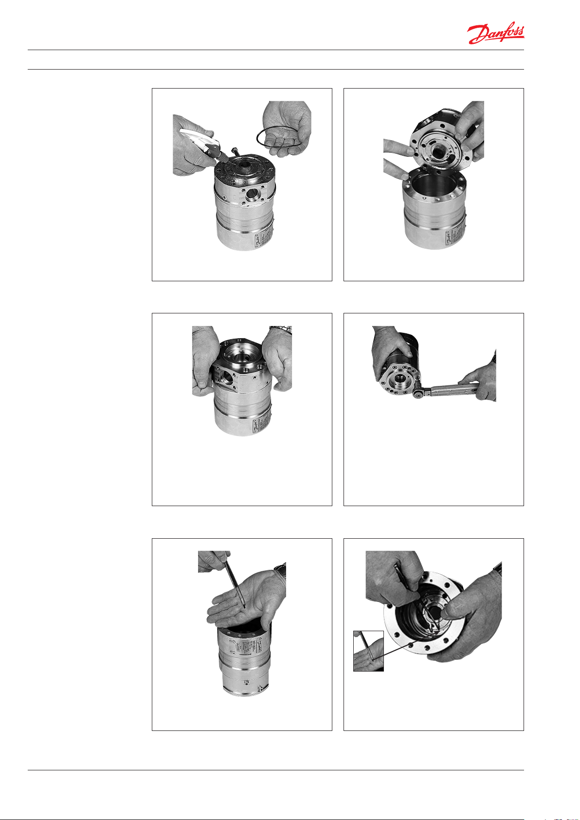
3. Mount new O-ring on port ange and
lubricate with water.
5.
Carefully press the port ange downwards.
Do not squeeze the O-ring. If the O-ring is
damaged, the pump will leak.
4. Position port ange by aligning pin hole
over guide pin.
6.
Lubricate the threads with PTFE lubrication
Insert screws on the port ange. Tighten
screws to a torque of 30 ± 3 Nm.
.
7.
Place a 10.5 mm guide pin in the port ange.
8
180R9281 | 521B1275 | DKCFN.PI.013.C5.02 | 07.2019
Page 9

Instruction Disassembling and assembling APP S 2.0-3.5 / APP S 674 2.0-3.5
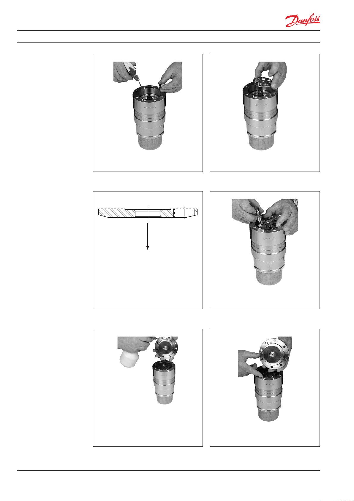
9. Ensure port plate is tted tightly against
the bottom.
Important: If valve plate is disassembled
8. Position port plate by using the guide pin.
Do not use force for this operation.
from cylinder barrel, please see page 15
before continuing.
Distance
block
10. Place the pump on a distance block. Make
sure, there is enough free space for the
shaft beneath the housing. Lubricate inside.
11. Carefully lower cylinder barrel into the
housing.
WARNING:
If cylinder barrel is dropped or lowered
too fast into housing, main bearing
and shaft bearing might be damaged.
Replacement can only be done at
Danfoss, Nordborg.
180R9281 | 521B1275 | DKCFN.PI.013.C5.02 | 07.2019
13. Lubricate and position the retainer guide.12. Place the spring in cylinder barrel.
9
Page 10
Instruction Disassembling and assembling APP S 2.0-3.5 / APP S 674 2.0-3.5
14. Lubricate retainer guide and position the
retainer ball. 15. Position the retainer plate.
16. Ensure the retainer plate is oriented
correctly.
18. Lubricate the piston shoes. Tilt retainer
plate for easier placement of swash plate.
If the swash plate has been disassembled
from end ange, see page 13 for
assembling of swash plate. Remember to
place the guide pin in the housing.
17. Lubricate and position the pistons in the
retainer plate and cylinder barrel.
19. Change and lubricate O-ring in the end
ange. Position end ange aligning pin
hole over the guide pin.
10
180R9281 | 521B1275 | DKCFN.PI.013.C5.02 | 07.2019
Page 11

Instruction Disassembling and assembling APP S 2.0-3.5 / APP S 674 2.0-3.5
20.
Lubricate and place two bolts in end ange.
Turn each bolt one round at a time to
ensure mounting ange is mounted as
straight downwards as possible. Be careful
not to squeeze the O-ring.
21. Screw in the rest of the bolts and tighten
all screws to a torque of 30 ± 3 Nm.
22. Lubricate and press new ceramic ring into
the shaft seal cover by using the press bush
tool.
WARNING:
Ensure that the face with rubber seal is
positioned against shoulder in shaft seal
ange.
23. Remove old O-ring and place the new one
on shaft seal cover.
24. Position the shaft seal distance ring.
180R9281 | 521B1275 | DKCFN.PI.013.C5.02 | 07.2019
11
Page 12
Instruction Disassembling and assembling APP S 2.0-3.5 / APP S 674 2.0-3.5
26. Mount new shaft seal with the carbon seal
face pointing upwards. Press seal down and
at the same time turn the seal clockwise
until spring stops at distance ring.25. Lubricate shaft with clean ltered water.
27. Right position of the spring can be
inspected through the ushing valve hole.
Shaft seal mounted.
29. Hold the cover down with one hand and
tighten the bolts with a torque of
12 Nm ± 1 Nm.
28. Position the shaft seal cover on shaft. Be
careful not to damage the ceramic ring.
WARNING!
Be careful, the shaft has sharp edges.
12
180R9281 | 521B1275 | DKCFN.PI.013.C5.02 | 07.2019
Page 13
Instruction Disassembling and assembling APP S 2.0-3.5 / APP S 674 2.0-3.5
3. Disassembling and
assembling of the swash
plate
O-ring
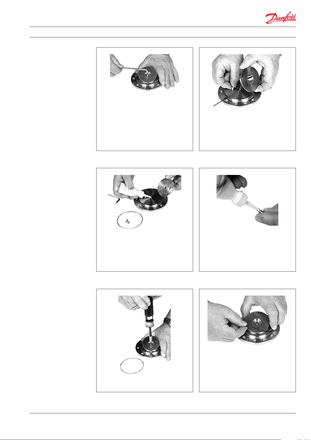
1. Unscrew centre bolt from swash plate. 2.
3. Place guide pin and carefully align swash
plate over guide pins.
4. Lubricate centre bolt thread with a PTFE
lubricant type.
Remove swash plate, guide pin and O-ring.
5. Position the centre bolt and tighten to
12 Nm ± 1 Nm.
180R9281 | 521B1275 | DKCFN.PI.013.C5.02 | 07.2019
6. Finally check the surface on the swash
plate for any marks or foreign particles
and place new O-ring.
13
Page 14

Instruction Disassembling and assembling APP S 2.0-3.5 / APP S 674 2.0-3.5
4. Disassembling and
assembling of cylinder
barrel and valve plate
1. Carefully lift valve plate assembly free
with the aid of a screwdriver.
O-ring
Backup ring
3. Mount the new back-up rings on the valve
plate. Then mount the O-rings.
O-ring
Backup
ring
2. Replace O-rings and backup rings on
valve plate.
4. Lubricate the new O-rings/back-up rings
and the liners in the cylinder barrel with
clean ltred water.
5. Carefully press, by hand, valve plate onto
cylinder barrel. The cylinder barrel is now
ready for mounting.
14
180R9281 | 521B1275 | DKCFN.PI.013.C5.02 | 07.2019
Page 15

Instruction Disassembling and assembling APP S 2.0-3.5 / APP S 674 2.0-3.5
5. Disassembling and
assembling of the
ushing valve
2. Carefully push the ushing valve up
through the outlet connection, using a
1. Remove shaft seal cover.
small screwdriver.
6. How to replace the
shaft seal
4. Flushing valve parts.3. Remove complete ushing valve set.
5. Press a new spring onto shoulders of the
poppet guide and the poppet. The spring
must be fastened on both collars. Then
mount new O-ring on the poppet guide.
Turn ushing valve upside down. If spring
is not properly assembled, it will fall of.
6. Lubricate valve with clean ltered water
and push by hand the valve into the hole.
Disassembling, please see Assembling, please see
Page 3 items 2 to 4 Page 11 item 22 to 24
Page 3 items 5 to 6 Page 12 items 25 to 29
180R9281 | 521B1275 | DKCFN.PI.013.C5.02 | 07.2019
15
Page 16

Instruction Disassembling and assembling APP S 2.0-3.5 / APP S 674 2.0-3.5
7. Changing pistons 7.1 Disassembling
To understand the pump design better, please
see the exploded view in item 9.
2. Loosen all screws on the pump except the
1. Disconnect the pump from the rest of the
system or close inlet valve.
two screws as shown in the picture below.
Note: There is still water inside the pump.
5. While holding the retainer plate with one
hand, carefully remove the pistons one by
one with the other hand.
4. Remove the ange. Remove pin or ensure
it stays in place. Ensure not to scratch the
swash plate surface.3. Unscrew the remaining screws.
16
180R9281 | 521B1275 | DKCFN.PI.013.C5.02 | 07.2019
Page 17

Instruction Disassembling and assembling APP S 2.0-3.5 / APP S 674 2.0-3.5
6. WARNING:
Ensure that the piston shoes and the
piston surfaces are not damaged
during removal. It is recommended
to place the pistons upside down on
an even and clean base/surface. 7. Remove retainer plate and ball.
10. Replace any worn parts.
9. Inspect the piston liners.8. Remove guide and spring.
180R9281 | 521B1275 | DKCFN.PI.013.C5.02 | 07.2019
17
Page 18

Instruction Disassembling and assembling APP S 2.0-3.5 / APP S 674 2.0-3.5
7.2 Assembling
1. Ensure the liner and the end of cylinder
barrel are wetted.
2. Place the spring.
5. Place the retainer plate and hold it with
one hand. Insert the pistons one by one
with the other hand.
4. Place the ball on the retainer plate.
WARNING!
Ensure right assembling and placement of
the retainer plate. See item 16, page 10.3. Place the guide.
6. Wet the pistons.
18
180R9281 | 521B1275 | DKCFN.PI.013.C5.02 | 07.2019
Page 19

Instruction Disassembling and assembling APP S 2.0-3.5 / APP S 674 2.0-3.5
7. Replace the O-ring and mount the ange.
Ensure the guide pin is mounted.
9. Mount the remaining bolts and cross
tighten them to a torque of 30 Nm ± 3 Nm.
8. Mount two screws as shown below and
tighten them.
10. Connect the pump to the rest of the
system.
11. Bleed the pump before starting it.
180R9281 | 521B1275 | DKCFN.PI.013.C5.02 | 07.2019
19
Page 20
Instruction Disassembling and assembling APP S 2.0-3.5 / APP S 674 2.0-3.5
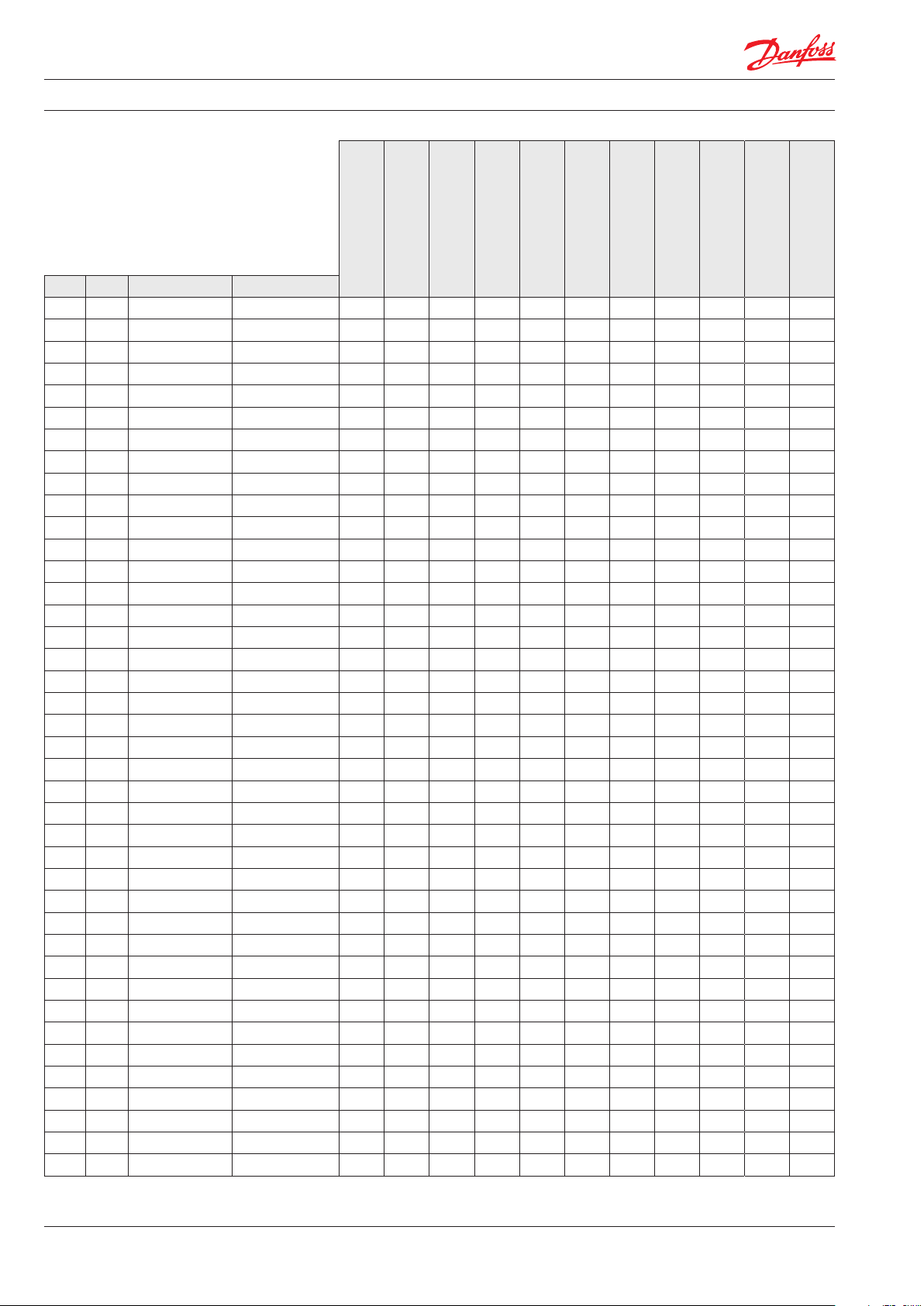
8. Spare parts list APP S 2.0-3.5
Pos. Qty. Designation Material
1 1 Housing Super Duplex / PEEK
2 2 Pin AISI 316
5 9 Screw M8x20 AIS I 316
9 1 O-ring NBR
11 1 End ange Super Duplex
31 1 Swash plate Super Duplex
32 1 Tight tting bolt Super Duplex
34 1 Pin PEEK
61 1 Cylinder barrel Super Duplex /PEEK
62 1 Spring Duplex
63 1 Spring guide PEEK
64 1 Retainer ball Super Duplex
65 1 Retainer plate Super Duplex
66 7 Piston Super Duplex /PEEK
67 1 Key AIS I 316
91 1 Port plate Super Duplex/PEEK
92 1 Valve plate Super Duplex
93 7 Back-up rin g PTFE
94 7 O -ring NBR
121 1 Port ange Super Duplex/PEEK
122 1 O-ring NBR
123 1 O-ring NBR
124 1 Shaf t seal NBR
125 1 Cover for shaft seal Super Duplex
126 1 Pin PEEK
127 3 Screw M6x16 AISI 316
128 8 Screw M8x55 AISI 316
130 3 O-ring NBR
131 2 Connection cover AIS I 316
132 2 O-ring NBR
133 8 Screw M8x25 AISI 316
134 3 Bleed screw M6 Super Duplex
144 2 Tailstock screw M12 AIS I 316
145 2 Check nut M12 AIS I 316
152 1 Valve cone PEEK
153 1 Spring Hastelloy C276
154 1 Valve guide Super Duplex
155 1 O -ring NBR
1 Press bush tools
1 Instruction
¹) Including PMI report
²) Including material cer ticate - no traceability
180B4265 - Seal set
180B4197 - Shaft seal
180B4231 - Cylinder barrel
180B4232 - Valve plate set
180B4233 - Retainer set
180B4234 - Piston set
APP S 2.0 - Swash p late on
request
APP S 2.5 - Swash plate on
request
180B4235 - Swash plate
APP S 3.0
180B4236 - Swash plate
APP S 3.5
x
x
x
1)
1)
1)
x
x
x
1)
x
1)
x
x
1)
x
1)
1)
x
x
1)
x
x
x
1)
x
1)
x
1)
x
x
x
1)
x
x
x
x
x
x
x
x
x
x
x
x
2)
x
x
x
x
x x x x x x x x x x x
180B4237 - Flushing valve set
x
x
2)
x
x
20
180R9281 | 521B1275 | DKCFN.PI.013.C5.02 | 07.2019
Page 21
Instruction Disassembling and assembling APP S 2.0-3.5 / APP S 674 2.0-3.5
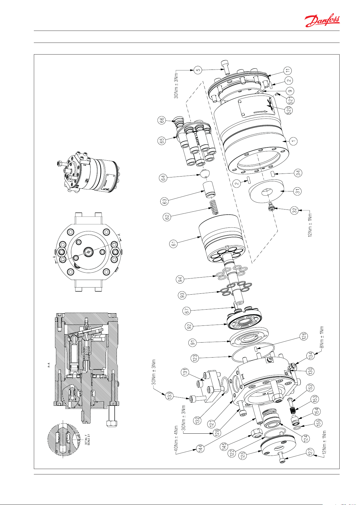
8.1 Explode view
APP S 2.0-3.5
180R9281 | 521B1275 | DKCFN.PI.013.C5.02 | 07.2019
21
Page 22

Instruction Disassembling and assembling APP S 2.0-3.5 / APP S 674 2.0-3.5
9. Spare parts list
APP S 674 2.0-3.5
Pos. Q ty. Designation Material
1 1 Housing Super Duplex / PEEK
2 2 Pin AIS I 316
5 9 Screw M8x20 AIS I 316
9 1 O-ring NBR
11 1 End ange Super Duplex
31 1 Swash plate Super Duplex
32 1 Tight tting bolt Super Duplex
34 1 Pin PEEK
61 1 Cylinder barrel Super Duplex/PEEK
62 1 Spring Duplex
63 1 Spring guide PEEK
64 1 Retainer ball Super Duplex
65 1 Retainer plate Super Duplex
66 7 Piston Super Duplex/PEEK
67 1 Key AIS I 316
91 1 Port plate Super Duplex/PEEK
92 1 Valve plate Super Duplex
93 7 Back- up ring PTFE
94 7 O -ring NBR
121 1 Port ange Super Duplex /PEEK
122 1 O-ring NBR
123 1 O-ring NBR
124 1 Shaf t seal NBR
125 1 Cover for shaft seal Super Duplex
126 1 Pin PEEK
127 3 Screw M6x16 AISI 316
128 8 Screw M8x55 AIS I 316
130 3 O-ring NBR
131 2 Connection cover AIS I 316
132 2 O-ring NBR
133 8 Screw M8x25 AIS I 316
134 3 Bleed screw M6 Super Duplex
144 2 Tailstock screw M12 AI SI 316
145 2 Check nut M12 AISI 316
152 1 Valve cone PEEK
153 1 Spring Hastelloy C276
154 1 Valve guide Super Duplex
155 1 O -ring NBR
1 Press bush tools
1 Instruction
1)
Including PMI report
2)
Including material cer ticate - no traceability
3)
Including material certicate - traceability
180B4265 - Seal set
APP S 674 3.0-3.5
180B4197 - Shaft seal
180B4231 - Cylinder barrel
180B4232 - Valve plate set
180B4233 - Retainer set
180B4234 - Piston set
180B4235 - Swash plate
APP S 674 3.0
180B4236 - Swash plate
APP S 674 3.5
x
x
x
1)
x
1)
x
1)
x
1)
x
x
1)
x
x
x
1)
x
1)
x
1)
x
x
x
1)
x
x
x
x
x
x
x
x
x
x
x
x
2)
x
x
x
x
x x x x x x x x x
180B4237 - Flushing valve set
x
x
2)
x
x
22
180R9281 | 521B1275 | DKCFN.PI.013.C5.02 | 07.2019
Page 23

Instruction Disassembling and assembling APP S 2.0-3.5 / APP S 674 2.0-3.5
9.1 Explode view
APP S 674 2.0-3.5
180R9281 | 521B1275 | DKCFN.PI.013.C5.02 | 07.2019
23
Page 24

Instruction Disassembling and assembling APP S 2.0-3.5 / APP S 674 2.0-3.5
10. When should the pistons
be replaced
This section provides guidance on, how to
determine whether the parts of the pump are
worn and should be replaced. In case of doubt
- the pistons must be replaced. The pictures
below are meant as a guideline for evaluating
the wear of the sliding surface.
Picture 1:
Cavitation of the piston shoes.
New inspection is required in 3,000-4,000
hours.
Note: If the pistons break down, the pump
will suer a disastrous breakdown.
Picture 2:
Cavitation of the piston shoes.
All pistons must be replaced within the
next 500-1,000 hours.
Picture 3:
Cavitation of the piston shoes.
All pistons must be replaced within the
next 100-200 hours.
24
180R9281 | 521B1275 | DKCFN.PI.013.C5.02 | 07.2019
Picture 4:
Abrasive wear of the piston shoes.
All pistons must be replaced immediately.
Page 25

Instruction Disassembling and assembling APP S 2.0-3.5 / APP S 674 2.0-3.5
180R9281 | 521B1275 | DKCFN.PI.013.C5.02 | 07.2019
25
Page 26
Danfoss A/S
High Pressure Pumps
DK-6430 Nordborg
Denmark
© Danfoss | DCS (im) | 2019.07
180R9281 | 521B1275 | DKCFN.PI.013.C5.02
 Loading...