

Page 1
Data sheet
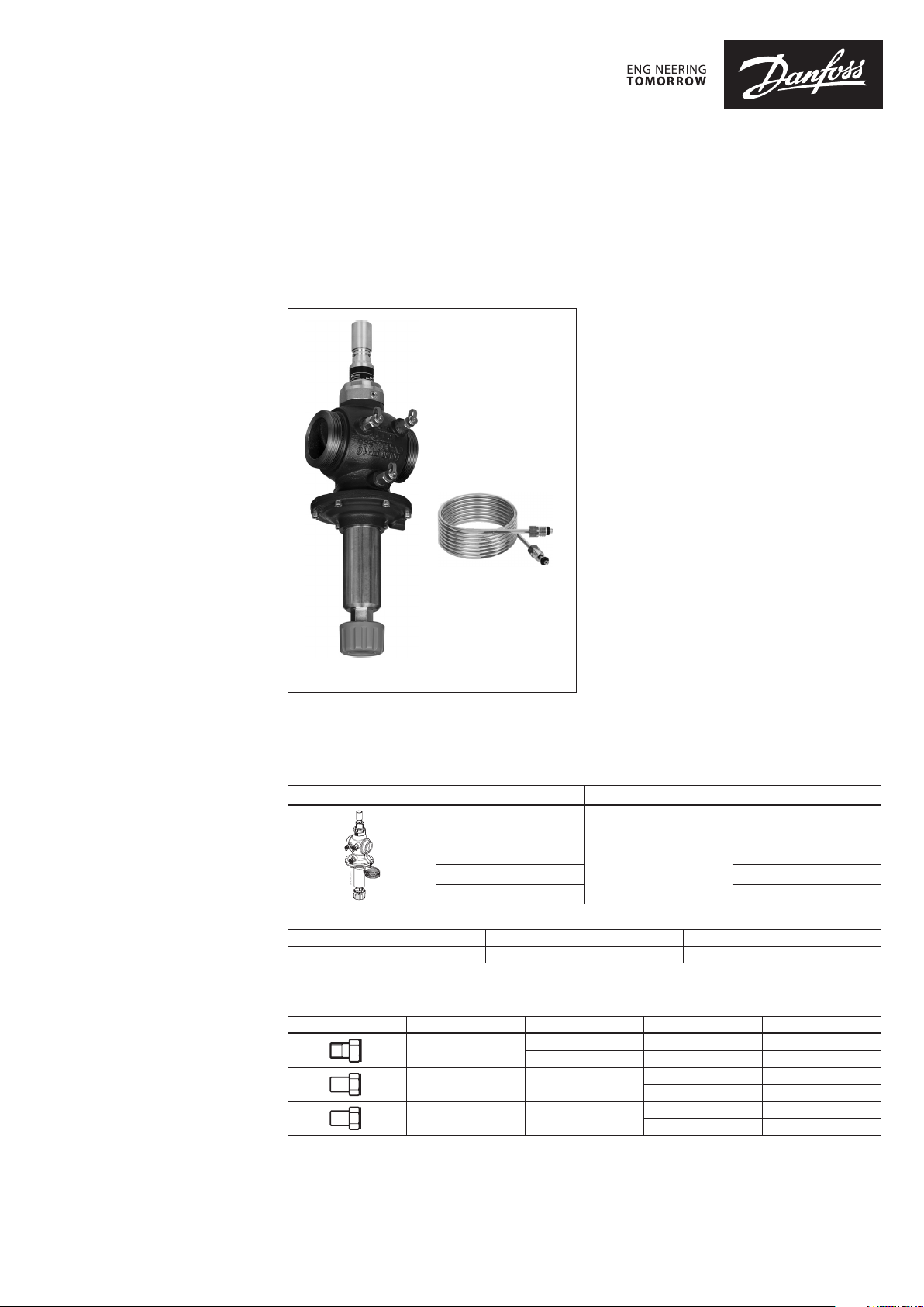
Pressure difference controller with integrated flow limiter
AB-PM DN 40-100
Description
AB-PM is a combined balancing valve.
It features 4 functions in one compact valve:
1. Differential pressure control
2. Flow limitation
3. Control valve with linear characteristic
4. Zone control
Reliable HVAC system with low total cost of
ownership:
Design:
• Easy, fast and flexible HVAC system design
Construction:
• Fast installation and easy setting
• Lower commissioning cost - no need for
balancing
• Faster project with staged handover
Operation:
• Perfect balance at all loads
• Guaranteed flow and p for users
• No problems caused by poor designed/
executed user installations
• Unoccupied zones do not impact other
AB-PM is ideal for staged installation and commissioning
users
• Flow verification and easy troubleshooting
Ordering AB-PM valve (including 2.5 m impulse tube (G ⁄ A), brass handle (003Z0695) impulse tube
connector (003L8151))
Picture
DN Connection Code No.
40 Ext thread (ISO228/1) G 2A 00 3Z1435
50 Ext.thread (ISO228/1) G 2½A 00 3Z1436
65
80 003Z1439
100 00 3Z144 0
Flange PN 16
003Z1438
Actuator
Typ e Power supply Code No.
AME435 QM
1)
For more inform ation see AME 435 QM datasheet
1)
24 VAC /DC 08 2H017 1
© Danfoss | 2018.01
Accessories
Picture Typ e To p ipe To va lve Code No.
Union connection
(CW617N) (1 pcs.)
Tail piece welding
(W.Nr. 10308)(1 pcs.)
Tailpiece welding INOX
(W. Nr. 1.4404) (1 pcs.)
R1½ DN40 003Z0279
R2 DN50 003Z0278
Weld
Weld
DN40 003Z0270
DN50 003Z0276
DN40 003Z12 75
DN50 00 3Z1276
VD.HR.D1.02 | 1
Page 2
Data sheet AB-PM DN 40-100
Ordering
Spare parts
Typ e Comments Code No.
Handle AB-PM (brass handle for spindle fixation) DN 40 -100 003Z0695
1.5 m 003L 8152
Impulse tube, with O-rings
Plastic impulse tube with connectors and adapters (industry pack) 10 pcs order quantity 003Z0689
Adapter large G .-R .; G 1/16 003Z0691
Plug for connecting impulse tube
Plug for connecting impulse tube on other valves (US standard) G 1⁄16-4⁄16-20 UNF-2B 00 3L8176
O-ring for impulse tube (set of 10 pcs) 2.90 × 1.78 0 03L8175
Plug for impulse tube connection ASV-I/M (set of 10 pcs) G1⁄16 A 00 3L8174
Needle plug set (1 pcs.) 003Z0100
Ext plug set (1 pcs.) 003 Z0106
Measuring needle, set (1 pcs.) 003 Z0107
Elbow test plug extension (1 pcs.) 003Z3944
Straight test plug extension (1 pcs.) 003Z3945
Straight plug extension set 003Z3946
2.5 m 003Z0690
5 m 003L 8153
3/8” – 1/16” 003L5042
¾” – 1/16” 003 Z0109
¼” – 1/16 003L 8151
Technical data
Nominal diameter DN 40 50 65 80 100
Qnom factory setting (∆pr 25 kPa) l/h 5000 6500 16800 19600 21000
Min. differential pressure (∆pa), Factory setting 1)kPa 42 60
Setting range
Nominal maximal pressure
Max. pressure drop 4
Control valve characteristics Linear
Shut-off leakage rate Acc. to ISO 5208 class A - no visible leakage
CV stroke mm 10 10 15 15 15
Connection
Connection actuator Danfoss standard
Flow medium
Medium temperature °C –10 … 120
Materials in water
Body Cast iron EN -GJL 250 (GG 25)
Membrane and O-rings EPDM
Springs W.Nr. 1.4568, W.Nr. 1.4310
Cone (Pc)
Seat (Pc) /(Cv) W.Nr. 1.4305
Cone (Cv) CuZn40Pb3 -CW 614N
Screw Stainless steel (A2)
Flat gasket NBR
Sealing agent (for test plugs) Dimenthcrylate Ester
1)
For other set tings see table 6
2)
Factory se tting see fig. 13 and 14
3)
Regardless of t he setting, the valve can modu late below 1 % of set flow.
2) 3)
Flow% 40 -100
∆p setting 0-20 turns 0-40 turns
bar
External thread (ISO
228/1) G2A
Water and water mixture for closed heating and cooling systems
according to plant type I for DIN EN 14868. When used in plant
Type II for DIN EN 14868 appropriate protec tive measures are
taken. The requirements of VDI 2035, part 1 + 2 are observed.
16 (PN16)
Flange (EN 1092-2)
CuZn40Pb3 -CW 614N,
W.Nr. 1.4305
2 | VD.HR.D1.02
© Danfoss | 2018.01
Page 3
Data sheet AB-PM DN 40-100
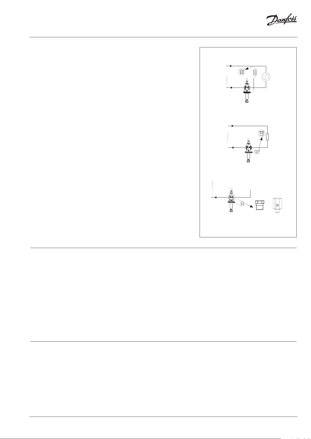
Mounting AB-PM DN 40-100 should be mounted in the
return pipe. The arrow on the valve body should
correspond with the flow direction of the
medium. The impulse tube should be connected
to the supply pipe using the included ¼”-/”
adaptor (003L8151).
Alternatively, the impulse tube can be connected
to a partner valve, such as ASV-BD or MSV-F2 1).
Using a partner valve offers additional service/
troubleshooting functions such as flow
verification, shut-off etc.
If the impulse tube is connected to the supply
pipe the AB-PM functions as a differential
pressure controller with flow limitation. The
impulse tube can also be connected to the
return pipe (upstream from the AB-PM) or to
the red test plug with adapter 003Z0691. In
that case the AB-PM will function as a pressure
independent control valve with 100% authority.
1)
For informatio n on partner valve see ASV a nd MSV-F2 datasheet
Impulse tube connection
DPCV
003L8151
Impulse tube connected to flow
PIBCV
003L8151
Impulse tube connected to return
PIBCV
003L8151
003Z0691
Commissioning
Service and trouble
shooting
When filling the system make sure to open the
supply valve before opening the return valve.
The pressure on the upper side of the membrane
(impulse tube) should always be higher than the
pressure on the lower side of the membrane (at
the valve)
Flush the impulse tube and ensure the HVAC
system is de-aired before starting the system.
For the setting procedure please refer to the
operating instructions enclosed with the
product.
It is recommended that an FV filter be installed in
the system supply pipe.
The valve can be manually shut off for service
purposes, up to 16 Bar.
AB-PM is equipped with 3 test plugs for flow
verification, service and trouble shooting.
+
Alternative
Fig. 1 AB-PM can be connected to flow or return with
impulse tube
Please check the following if the valve does not
function correctly:
1. Is the flow direction through the valve correct?
2. Is the impulse tube fitted correctly and are any
test plugs open?
3. Is the valve shut-off open? (see operating
instructions)
4. Is the available pressure big enough?
© Danfoss | 2018.01
VD.HR.D1.02 | 3
Page 4
Data sheet AB-PM DN 40-100
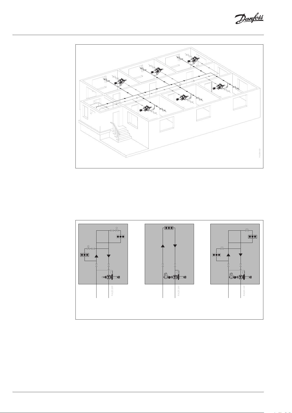
Application
-variable flow systems
Zone 1
Zone 3
Zone 2
Zone 6
Zone 5
Heating/
cooling
Zone 4
station
Fig. 2 Staged commissioning – 1st stage : ensuring Δp and flow for each zone
AB-PM DN 40 to 100 is the ideal solution for
applications where a so called staged installation,
Typical applications are shopping malls and shell
& core office buildings.
hand over and commissioning is used. In such
cases, the 1st stage is installation of backbone
piping without terminal units. AB-PM is used as
DPCV with flow limitation, ensuring the specified
The AB-PM ensures the required flow for each
zone and maintains hydronic balance in the
system.
design pressure and flow to each zone. The 2nd
stage is then the installation of terminal units.
4 | VD.HR.D1.02
DPCV: several fancoils with
individual room control
Fig. 3 Staged commissioning – 2nd stage : Installation of terminal units
PIBCV: zone control for
one terminal unit
In the 2nd stage of commissioning the installation
of terminal units can be done. Optionally the
AB-PM can be changed from differential pressure
controller to pressure independent control valve.
This allows flexibility when designing the zones.
If only one terminal unit is used in the zone, the
AB-PM as a PIBCV can be used to control that
unit and no additional valves are needed.
DPCV: Zone control
for several fancoils
© Danfoss | 2018.01
Page 5

Data sheet AB-PM DN 40-100
Flow verification /trouble
shooting
Differential pressure legend
To verify that an installation functions per the
design specifications the AB-PM (DN 40-100) has
test plugs that allow measuring of the pressure
difference ∆pr or ∆pcv across the valve. In this
way the pressure difference and flow can be
verified for handover or troubleshooting.
At handover of the base building when the HVAC
design conditions are specified but components
are not yet installed in the zone, the differential
pressure and flow for the valve and loop can
only be verified by installing a bypass with the
same dp as specified for the zone. For quick hand
over, without flow verification, the calculated dp
can be pre-set on the valve for the dp and flow
demand of the loop.
In the 2nd stage of commissioning when the
HVAC system has been installed in the zone, the
differential pressure and flow can be verified for
handover and troubleshooting.
The differential pressure can be measured using
the following methods:
003L8151
DPCV: Measure differential pressure from AB-PM
to installed partner valve (∆pr =p0 − p1).
PIBCV: Measure the differential pressure across
the control valve (∆Pcv =p1 − p2).
To calculate the flow below formulas are used:
DPCV:
∆pr=p0 − p
Q=kvcv × √p
1
r
PIBCV:
∆pCv=P1 − P
2
Q=kvcv × √pcv
For kvcv values see datasheet “AB-QM flow
checker DN 40-250”
For trouble shooting the available pressure can
be verified, Closing the AB-PM valve fully and
measuring p0 – p2.
Verifying the pressure and flow can be done
by using Danfoss PFM or other dp measuring
devices (select valve type: AB-QM)
P1-P
3
P1-P
2
3
-P
0
=P
a
∆p
∆p
v
Q = needed desi gn flow for the loop
Δpr = needed dif ferential pressure for the l oop
Δpv = differe ntial pressure on AB-PM
Δpa = min. needed d ifferential pressure ove r
bo th AB-PM and loop
Δpa = Δpv + Δp
r
-P
=P
∆p
1
0
r
Fig. 4 Differential pressure legend
Sizing AB-PM is to be sized based on the needed flow
(Q) and the needed differential pressure drop for
the zone (pr).
Max flow /∆pr for all sizes are presented in the
sizing guide in fig. 5.
When pipe dimension has been selected, specific
sizing, selection and setting can be identified
based on Q and ∆pr in fig. 6-10.
Alternatively table 1-5 can be used for AB-PM
sizing as well.
Flow
direction
P
P
3
ΔpV = p1 − p3
Δpr = p0 − p1 (as DPCV)
Δpcv = p1 − p2 (as PIBCV for f low validation)
∆pa = p0 − p
3
1
P
2
P0-P
P
0
1
For needed flow and differential pressure
outside specified in graphs and tables, setting
can be calculated by linear distribution of
setting.
For minimum needed available differential
pressure (∆pa ) at Q nominal see table 6.
© Danfoss | 2018.01
VD.HR.D1.02 | 5
Page 6

Data sheet AB-PM DN 40-100
13000
60
Q [l/h]
∆pr[kPa]
55000
60
FLOW [L/H]
ΔPr [kPa]
Sizing graph - ΔP/ max. flow
50000
45000
40000
35000
30000
25000
20000
15000
10000
5000
AB-PMHP DN 10-32
0
10 15 20 25 30 35 40 45 50 55
1)
See datasheet AB-PM
DN 10-32
Fig. 5
DN 100
DN 80
DN 65
DN 50
DN 40
1)
Sizing
Example 1
Given : Design flow to zone
4200 l/h, pressure drop over
the zone at design flow 25 kPa.
Solution: AB-PM DN 40 is
selected. ∆p setting is kept
at factory setting and flow
limitation is changed to 80 %.
AB-PM will control differential
pressure of 25 kPa when
design flow is achieved and
the flow to the zone will be
limited to 4200 l/h
DN 40
12000
11000
10000
9000
100 %
8000
7000
6000
5000
Example 1
4000
3000
2000
90 %
80 %
70 %
60 %
50 %
40 %
10 15 20 25 30 35 40 45 50 55
Fig. 6
DN 40 Flow limitation on Δp factory setting
Δpr
[kPa]
Table 1
40% 50% 60% 70% 80% 90%
10 4600 5520 6348 7084 7728 8280 9200
15 4000 4800 5520 616 0 6720 7200 8000
20 3300 3960 455 4 5082 5544 5940 6600 9200
25 2500 3000 3450 3850 4200 4500 5000 8000 10200
30 2070 2310 2520 2700 3000 6600 920 0 1110 0
35 5000 8000 10200 119 00
40 3000 6600 9200 1110 0
45 5000 8000 1020 0
50 315 0 6600 9200
55 5000 8000
60 3150 6600
5 turns
10 tur ns 15 tu rns
Factory
setting
100%
/0 turns 5 turns 10 tu rns 15 tu rns 20 turns
Q [l/ h]
20 turns
∆p setting [kPa]
6 | VD.HR.D1.02
© Danfoss | 2018.01
Page 7

Data sheet AB-PM DN 40-100
16000
60
Q [l/h]
∆pr[kPa]
60
Q [l/h]
∆pr[kPa]
Sizing
DN 50
15000
14000
13000
12000
100 %
11000
90 %
10000
80 %
9000
70 %
8000
60 %
7000
50 %
6000
40 %
5000
4000
3000
10 15 20 25 30 35 40 45 50 55
Fig. 7
DN 50 Flow limitation on Δp factory setting
Δpr
[kPa]
Table 2
40% 50% 60% 70% 80% 90%
10 5520 6750 7920 9030 10 080 1107 0 12000
15 478 4 5850 6864 7826 8736 9594 10 400
20 3910 4781 5610 6396 714 0 7841 8500 12000
25 3656 4290 4891 5460 5996 6500 1040 0 1309 5
30 3085 3444 3782 4100 8500 116 40 14155
35 6500 10 088 12825 15390
40 410 0 8245 114 00 1415 5
45 6305 9880 1282 5
50 3977 8075 114 00
55 6175 9880
60 3895 8075
5 turns 10 tu rns 15 tu rns 20 turns
Factory
setting
100%
/0 turns 5 turns 10 tu rns 15 tu rns 20 turns
Q [l/ h]
∆p setting [kPa]
DN 65
30000
28000
26000
24000
100 %
22000
90 %
20000
80 %
18000
70 %
16000
14000
60 %
12000
50 %
10000
8000
40 %
6000
10 15 20 25 30 35 40 45 50 55
Fig.8
DN 65 Flow limitation on Δp factory setting
Δpr
[kPa]
Table 3
40% 50% 60% 70% 80% 90%
10 8432 111 60 14136 1736 0 198 40 22320 24800
15 7616 100 80 1276 8 156 80 1792 0 2016 0 22400
20 6732 8 910 112 86 138 60 158 40 1782 0 1980 0 24800
25 7560 9576 1176 0 134 40 15 120 16 800 22400 25840
30 6075 7695 9450 108 00 1215 0 135 00 198 00 23560 27740
35 6650 760 0 8550 9500 168 00 21280 25840 29450
40 13500 18810 23560 27 740
45 9500 15960 21280 25840
50 12825 18810 23560
55 9025 15960 2128 0
60 12825 18810
20 turns 30 turns 40 tur ns10 tur ns
Factory
setting
∆p setting [kPa]
100%
/0 turns 10 tu rns 20 turns 30 turns 40 turns
Q [l/ h]
© Danfoss | 2018.01
VD.HR.D1.02 | 7
Page 8

Data sheet AB-PM DN 40-100
51000
60
Q [l/h]
∆pr [kPa]
60
Q [l/h]
∆pr[kPa]
Sizing
DN 80
41000
39000
37000
35000
33000
31000
100 %
29000
27000
90 %
25000
80 %
23000
70 %
21000
60 %
19000
50 %
17000
15000
40 %
13000
11000
9000
10 15 20 25 30 35 40 45 50 55
Fig. 9
DN 80 Flow limitation on Δp factory setting
Δp
r
[kPa]
Table 4
40% 50% 60% 70% 80% 90%
10 1512 0 18113 2079 0 23373 25956 28350 3150 0
15 13536 16 215 18612 20924 23237 25380 28200
20 11616 13915 15972 1795 6 19941 217 80 2420 0 315 00
25 9408 1127 0 1293 6 14543 16150 17640 1960 0 28200 35000
30 9504 10 685 11866 12960 144 00 24200 3150 0 376 00
35 19600 28200 35000 40000
40 14400 24200 31500 376 00
45 19600 28200 35000
50 14400 24200 31500
55 19600 28200
60 14400 24200
20 turns 30 turns 4 0 turns10 tur ns
Factory
setting
∆p setting [kPa]
100%
/0 turns 10 tu rns 20 turns 30 turns 40 turns
Q [l/ h]
DN 100
49000
47000
45000
43000
41000
39000
37000
35000
100 %
33000
90 %
31000
29000
80 %
27000
70 %
25000
23000
60 %
21000
50 %
19000
17000
40 %
15000
13000
11000
10 15 20 25 30 35 40 45 50 55
Fig . 10
DN 10 0 Flow limitation on Δp factory setting
Δpr
[kPa]
Table 5
40% 50% 60% 70% 80% 90%
10 16470 2 0130 23607 26901 30012 32940 36600
15 14490 177 10 20769 23 667 26404 28980 32200
20 12150 14 850 17415 19 845 2 2140 24300 27000 36600
25 13545 154 35 1722 0 1890 0 21000 32200 40600
30 114 80 126 00 14000 27000 36600 44400
35 21000 32200 40600 48000
40 14000 27000 36600 44400
45 21000 32200 40600
50 14000 27000 36600
55 21000 32200
60 14000 27000
10 tur ns 20 tur ns 30 turns 40 turns
Factory
setting
∆p setting [kPa]
100%
/0 turns 10 tu rns 20 turns 30 turns 40 turns
Q [l/ h]
8 | VD.HR.D1.02
© Danfoss | 2018.01
Page 9

Data sheet AB-PM DN 40-100
Min. differential pressure
(Δpa)
Nominal diameter ≤Factory setting ∆p setti ng
≤100% /0 turns
DN40 42 52 63 74 85
DN50 42 52 63 74 85
DN65 60 72 83 94 105
DN80 60 72 83 94 105
DN100 60 72 83 94 105
Table 6
1)
If applicati on requires less dpr, for valve will be h igher so flow validation a cross valve is needed in order to incr ease.
5 turns
(pr >= 20 kPa )
Setting The AB-PM valves are factory preset to min. ∆p
setting with 100% flow.
For changing the setting please use the
following procedure:
Setting the desired differential pressure:
the setting on the AB-PM can be changed by
turning the setting spindle to allow higher
differential pressure. Turning the spindle
clockwise increases the setting; turning it
counter clockwise reduces the setting.
If the setting is not known, turn the spindle fully
clockwise. With this the setting on AB-PM is at
maximum value within setting range. Now turn
the spindle backwards a number of times (n)
as described in Fig. 13 or 14 until the required
differential pressure setting is obtained.
1)
10 tu rns
(pr >= 25 kPa )
pa [kPa]
15 tu rns
(pr >= 30 kPa )
20 turns
(pr >= 35 kPa )
The calculated flow can be adjusted easily with
a standard tool. The presetting scale indicates
values from 100 % flow to 40 %. Clock wise
turning would decrease the flow value while
counter clock wise would increase it.
Danfoss recomm ends a presetting/fl ow from 40 % to 100 %.
Factory pr esetting is 100 %.
DN Wrench
40-50 50
65-100 42
Design
1. Shut off knob
2. Differential pressure setting
spindle
3. Membrane
4. DP cone
5. Seat
6. Valve body
7. Control valve cone
8. Locking screw
9. Scale
10. Stuffing box
11. Spindle
12. Impulse tube
13. Brass handle
Fig. 11 Setting of differential pressure is done with
standard tool
Adjusting the flow limitation:
To give lower flow than factory setting the
% scale on the AB-PM need to be adjusted
according to sizing diagrams (figure 6 to 10).
one turn
is 10%
Max. 25 Nm
Fig. 12 Setting of flow limitation with standard tool
DN 40 50
5 5
Factory presetting DN 40-50
∆p setting min. setting (0 turns)
Flow % 10 0%
n Δp setting
(turns)
0 turns
… …
20 turns Max. setting
Min. setting
(factory setting)
© Danfoss | 2018.01
Do not turn the sp indle more than 20 turns as it will b ecome disengaged.
Fig. 13 AB-PM DN 40-50
VD.HR.D1.02 | 9
Page 10

Data sheet AB-PM DN 40-100
Design
1. Shut off knob
2. Differential pressure setting
spindle
3. Membrane
4. DP cone
5. Seat
6. Valve body
7. Control valve cone
8. Locking screw
9. Scale
10. Stuffing box
11. Spindle
12. Impulse tube
13. Brass handle
n
(turns)
0
… …
40 Max. setting
Factory presetting DN 65 -100
∆p setting min. setting (0 turns)
Flow % 10 0%
65 80 100
DN
42 13 23
Δp setting
Min. setting (factory
setting)
65 80 100
DN
Do not turn the sp indle more than 40 turns as it wil l become disengaged.
Fig. 14 AB-PM DN 65-100
DPCV PIBCV
AB-PM is a combined automatic balancing valve.
It works as differential pressure controller (DPCV)
or pressure independent control valve (PIBCV),
flow limiter and zone controller/control valve.
As DPCV it keeps a constant differential pressure
over the control loop and when installed as a
PIBCV it keeps the pressure constant over the
control valve ensuring it full authority.
Higher pressure acts on the lower side of the
control membrane (3) via an impulse tube (12)
while the lower pressure in the return pipe acts
on the upper side of the membrane (use either
membrane or diaphragm. Do not mix these
two, it will help clarity). When available pressure
increases at partial loads, the membrane closes
and thus keeps the differential pressure stable.
The control part of AB-PM is working as a
flow limiter. This enables to set a required
combination of the design flow as well as the
needed ∆p. By presetting the AB-PM, the flow
rate is defined based on the pressure demand of
the loop or terminal unit.
With an actuator mounted on the valve, AB-PM
can be used as a zone valve. When the AB-PM is
converted to a PICV it can be used, together with
an actuator, as a full authority control valve with
either a linear or a logarithmic characteristic.
10 | VD.HR.D1.02
© Danfoss | 2018.01
Page 11

Data sheet AB-PM DN 40-100
Dimensions
1
H
2
H
L
1
3
H
b
AB-PM DN 40, 50
L
H
Typ e
DN40 110
DN50 130 G 2 ½ (ISO228/1) 7. 8
1
H
1
168 273 280
L
1
H
1
2
mm
AB-PM + AME 435 QM
H
3
G 2 (ISO228/1) 6.9
b
Weight
(kg)
3
H
a
2
H
© Danfoss | 2018.01
AB-PM DN 65-100
Typ e
L
H
H
1
1
H
2
mm
AB-PM + AME 435 QM
3
(EN 1092-2)
a
Weight
(kg)
DN 65 290 218 388 330 185 41
DN 80 310 223 393 335 200 46
DN 10 0 350 239 451 350 220 64
VD.HR.D1.02 | 11
Page 12

Danf
already on order pro
All trademarks in this material are property of the respec
Data sheet AB-PM DN 40-100
Tender text
AB-PM DN 40-100 is a combined differential pressure controller for dynamic hydronic balance.
•
The valve should be able to ensure hydronic balance for each zone with one or more terminal units.
•
Valve shall have flexible functionality as either DPCV or PIBCV.
• The valve can be connected to either flow or return pipe via impulse tube
• With impulse tube connected to flow, the valve should keep differential pressure across the
branch by membrane driven controller.
•
With impulse tube connected to the return, the valve should control the flow on every terminal unit
• Valve should have shut-off function.
• Valve should have possibility to mount actuator without effecting presetting.
• Valve should have variable setting. Setting value should allow to set a combination of needed
differential pressure and flow for zone.
• Setting should be lockable to prevent unauthorized change.
• Control valve should have metal to metal sealing to ensure sufficient performance of differential
pressure control at low flows.
• Shut-off service function should be possible to do with hand or a tool. The Dp controller should
have soft sealing to ensure suficient closing in case of zero flow
• Valve should be delivered with min. 2.5 m impulse tube. Diameter of impulse tube should not be
bigger than 1.2 mm.
• Valve should be delivered in reliable packaging for safe transport and handling.
Product characteristics:
a) Pressure class: PN16
b) Max. pressure drop across AB-PM: 4 bar
c) Temperature range: –10 … 120 °C
d) Connections size: DN 40-100
e) Connection type: External tread ISO 228/1 (DN 40, DN50 ), Flange EN1092-2 (DN 65-100)
f) Installation: in return pipe with connection via impulse tube to flow or return pipe
g) Setting range: Flow: 40-100%, ∆p setting : 0-20 turns (DN40, DN50), 0-40 turns (DN65-DN100)
h) Nom. flow at factory setting (∆pr 25 kPa): 5000l/h (DN40), 6500 l/h (DN50), 16800 l/h (DN65),
19600 (DN80), 21000 (DN100)
i) Minimum differential pressure across valve and zone at factory setting 45 kPa (DN40, DN50),
60 kPa (DN65-100)
oss can accept no responsibility for possible errors in catalogues, brochures and other printed material. Danfoss reserves the right to alter its products without notice. This also applies to products
vided that such alterations can be made without subsequential changes being necessary eady agreed.
12 | VD.HR.D1.02
tive companies. Danfoss and the Danfoss logotype are trademarks of Danfoss A/S. All rights reserved.
© Danfoss | DHS-SRMT/SI | 2018.01
 Loading...