

Data sheet
Preassembled automatic balancing valve set
AB-PM Rack set DN 15-20, PN10
Description
Ordering
Technical data
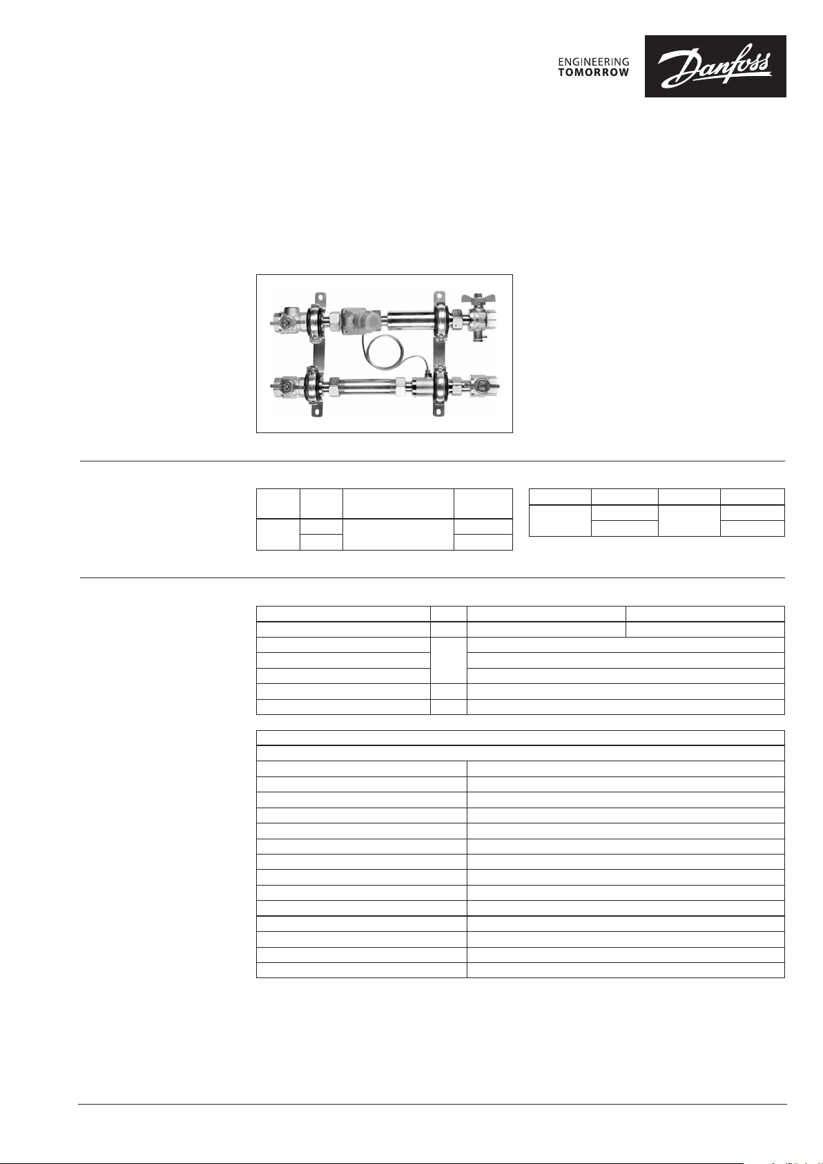
AB-PM Rack set is preassembled automatic
balancing solution for manifolds. The rack set is
installed in front of manifold in either radiator or
oor heating systems.
Benefits:
Automatic manifold balancing solution
*Reliable heating system
-Proper heat distribution even at partial load
-Filter to remove dirt before manifold
*Faster and simple installation
*Prepared for heat meter installation
Typ e DN
AB-PM
Rack set
AB-PM specification DN 15 20
Qnom (at 100% set ting) l/h 300 600
Max. pressure at zero load
Max dierential pressure (pa) 400
Min. dierential pressure (pa) 18
Nominal maximal pressure bar 10 (PN10)
Medium temperature °C -10 … +120
Connection ball-valves
(ISO228/1)
15
20 003Z3173
F/F ¾”
Code No.
00 3Z3171
kPa
Typ e
TWA-Z NO
Power supply Cable length
24 V AC
1)
230 V AC 08 2F1264
22
1.2 m
Code No.
08 2F1260
© Danfoss | 2017/03
Materials in water
AB-PM
Valve body DZR Brass (CuZn36Pb2As - CW 602N)
Membrane and O-ring EPDM
Spring W.Nr. 1.4568, W.Nr. 1.4310
Cone (PC) W.Nr. 1.4305
Seat (PC) EPDM
Cone (CV) CuZn40Pb3 - CW 614N
Seat (CV) DZR Brass (CuZn36Pb2As - CW 602N)
Flat gasket NBR
Screw Stainless Steel (A2)
Sealing agent Dimethacrylate Ester
Ball valve Brass (CW617N)
Pipe Steel (P235GH)
Gasket PTFE
Sealing agent: Connections AFM34
VD.HR.C1.02 | 1
Data sheet Preassembled automatic balancing valve set AB-PM
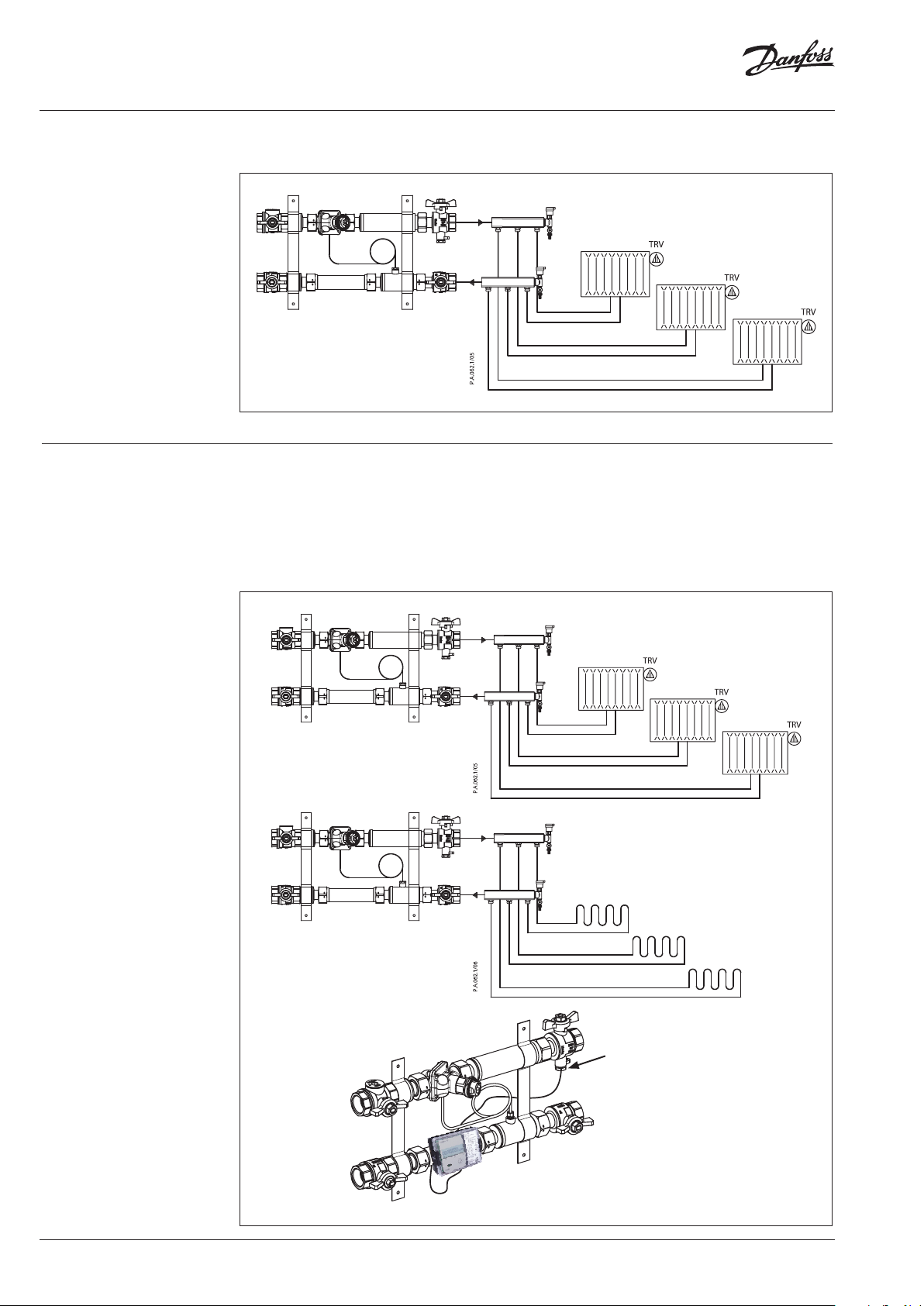
Application
Application
AB-PM rack set should be mounted in front of manifold with AB-PM in the ow direction.
The mounting bracket to be screwed onto back plate or wall.
AB-PM is designed to be used in heating systems in residential applications. It can be used both in radiator
or oor heating systems.
AB-PM provides proper balance even at partial loads and limitation of maximal ow is simple and fast.
In addition, programmable zone control (night setback or holiday mode) is available by using On/O
actuator (TWA-Z /ABN A5), connected to a room controller (TP5001M / TPOne).
The AB-PM Rack set is prepared for heat meter installations in return ow and temperature probe
connection.
2 | © Danfoss | 2017/03
Temperature sensor
VD.HR.C1.02

Data sheet Preassembled automatic balancing valve set AB-PM
Sizing
AB-PM is to be sized based on needed ow (Q) and needed dierential pressure drop for the loop.
flow [l/h]
∆pr [kPa]
100 %
90 %
80 %
70 %
60 %
50 %
40 %
30 %
20 %
DN 15
100 %
90 %
80 %
70 %
60 %
50 %
40 %
30 %
20 %
flow [l/h]
∆pr [kPa]
DN 20
AB-PM DN 15 setting
DN 15 ow [l/h] - average
Δpr [kPa] 20 % 30 % 40 % 50 % 60 % 70 % 80 % 90 % 100 %
5 80 120 160 200 240 280 320 360 400
6 77 116 154 193 231 270 308 347 385
7 74 111 148 185 222 259 296 333 370
8 70 105 140 175 210 245 280 315 350
9 65 98 130 163 195 228 260 293 325
10 60 90 120 150 180 210 240 270 300
Q
at ΔT 20 °C 7.0 kW
max
…
13 43 65 86 108 129 151 172 194 215
14 37 56 74 93 111 130 148 167 18 5
15 30 45 60 75 90 105 120 135 150
Example
Given:
Design flow through radiators loop:
420 l/h
Pressure drop trough the loop at
design flow: 10 kPa
Solution:
AB-PM DN 20 is selected. Set to 70
% (= 420/600), AB-PM will control
differential pressure of 10 kPa when
design flow is achieved. It will at any
loads including keep it under 22 kPa
at zero load, while limiting the flow to
radiator system to 420 l/h
Design
1. AB-PM valve
2. Impulse tube
3. Impulse tube connection piece
4. Ball valve
5. Ball valve with temp sensor
6. Ball valve with filter
7.
Intermediate piece for heat meter
8. Mounting bracket
AB-PM DN 20 setting
①
ow [l/h] - average
⑧
③
⑤
④
DN 20
∆pr [kPa] 20 % 30 % 40 % 50 % 60 % 70 % 80 % 90 % 100 %
5 155 235 310 390 470 545 625 700 780
6 150 225 300 375 450 525 600 675 750
7 140 215 285 355 425 495 570 640 710
8 135 205 270 340 410 475 545 610 680
9 130 190 255 320 385 450 510 575 640
10 120 180 240 300 360 420 480 540 600
Q
at ΔT 20 °C 13.9 kW
max
…
13 85 13 0 170 215 260 300 345 385 430
14 75 110 15 0 185 220 260 295 335 370
15 60 90 120 150 180 210 24 0 270 300
⑧
⑥
②
④
VD.HR.C1.02
⑦
© Danfoss | 2017/03 | 3

Danf
already on order pro
All trademarks in this material are property of the respec
Data sheet Preassembled automatic balancing valve set AB-PM
Dimensions
L
HH
W2
W1
20
65
Typ e DN
AB-PM
Rack set
DN 20DN 15
W1
20
82
H1 H2 W1 W2 L Weight
mm kg
15 79 26
20 81 34 3.01
110 220 336
2.81
W2
L
oss can accept no responsibility for possible errors in catalogues, brochures and other printed material. Danfoss reserves the right to alter its products without notice. This also applies to products
vided that such alterations can be made without subsequential changes being necessary eady agreed.
4 | © Danfoss | DHS-SRMT/SI | 2017/03
tive companies. Danfoss and the Danfoss logotype are trademarks of Danfoss A/S. All rights reserved.
VD.HR.C1.02
 Loading...