

MAKING MODERN LIVING POSSIBLE
VLT® Active Filter AAF00x Operating Instructions

Contents VLT Active Filter AAF 00x
Contents
1 How to Read these Operating Instructions
1.1.1 Copyright, Limitation of Liability and Revision Rights 4
2 Safety
2.1.2 General Warning 5
2.1.3 Before Commencing Repair Work 5
2.1.4 Special Conditions 5
2.1.5 Avoid Unintended Start 6
2.1.6 IT Mains 6
3 Introduction to VLT Active Filter AAF00x
3.1.1 Working Principle 7
3.1.2 Filter Configurator 8
3.1.3 Ordering Form type code 9
4 How to Install
4.1 How to Get Started
4.2 Pre-installation
4
5
7
10
10
10
4.2.1 Planning the Installation Site 10
4.2.2 Receiving the Active Filter 10
4.2.3 Transportation and Unpacking 10
4.2.4 Lifting 11
4.2.5 Mechanical Dimensions 12
4.3 Mechanical Installation
4.3.3 Terminal Locations - Frame size D 18
4.3.4 Terminal Locations - Frame size E 18
4.3.5 Cooling and Airflow 19
4.4 Field Installation of Options
4.4.1 Installation of Input Plate Options 21
4.5 Electrical Installation
4.5.1 Power Connections 22
4.5.7 Current Transformer (CT) 28
4.5.8 Auto CT Detection 31
4.5.9 Summation Transformers 31
4.5.10 Active Filter Operating with Capacitor Banks 32
17
21
22
4.5.11 Fuses 34
4.5.13 Control and CT Cable Routing 34
4.5.15 Unscreened Control Wires 36
4.6.1 Electrical Installation, Control Cables 37
4.7 Paralleling of Active Filter Units
MG.90.V2.02 - VLT® is a registered Danfoss trademark 1
39

Contents VLT Active Filter AAF 00x
4.8 Final Set-Up and Test
5 How to Operate the Active Filter
5.1.1 How to Operate Graphical LCP (GLCP) 44
5.1.6 Tips and Tricks 47
6 How to Programme
6.2.1 Main Menu 54
6.3 0-** Operation/Display
6.4 5-** Digital I/O Mode
6.5 8-** General Settings
6.6 14-2* Trip Reset
6.7 15-0* Operating Data
6.8 16-0* General Status
6.9 300-**
6.10 301-**
6.11 Parameter Lists
6.11.1 Default settings 76
41
44
51
54
59
63
66
67
71
73
75
76
6.11.2 Operation/Display 0-** 77
6.11.3 Digital In/Out 5-** 78
6.11.4 Comm. and Options 8-** 78
6.11.5 Special Functions 14-** 79
6.11.6 FC Information 15-** 80
6.11.7 Data Readouts 16-** 81
6.11.8 AF Settings 300-** 82
6.11.9 AF Readouts 301-** 82
7 RS-485 Installation and Setup
7.2 Network Configuration
7.3 FC Protocol Message Framing Structure
7.3.1 Content of a Character (byte) 84
7.3.3 Telegram Length (LGE) 85
7.3.5 Data Control Byte (BCC) 85
7.3.6 The Data Field 85
7.3.8 Parameter Number (PNU) 87
7.3.9 Index (IND) 87
83
84
84
7.3.10 Parameter Value (PWE) 87
7.3.11 Data Types Supported by VLT AutomationDrive 87
7.3.12 Conversion 87
7.3.13 Process Words (PCD) 88
7.4 How to Access Parameters
2 MG.90.V2.02 - VLT® is a registered Danfoss trademark
88

Contents VLT Active Filter AAF 00x
7.4.1 Parameter Handling 88
7.4.3 IND 88
7.4.4 Text Blocks 88
7.4.5 Conversion Factor 88
7.4.6 Parameter Values 88
8 General Specifications
8.1 Electrical Data
8.1.1 Power Rating 89
9 Troubleshooting
89
89
93
MG.90.V2.02 - VLT® is a registered Danfoss trademark 3
How to Read these Operating... VLT Active Filter AAF 00x
11
1 How to Read these Operating Instructions
1.1.1 Copyright, Limitation of Liability and
Revision Rights
This publication contains information proprietary to
Danfoss. By accepting and using this manual the user
agrees that the information contained herein will be used
solely for operating equipment from Danfoss or equipment
from other vendors provided that such equipment is
intended for communication with Danfoss equipment over
a serial communication link. This publication is protected
under the Copyright laws of Denmark and most other
countries.
Danfoss does not warrant that a software program
produced according to the guidelines provided in this
manual will function properly in every physical, hardware
or software environment.
Although Danfoss has tested and reviewed the documentation within this manual, Danfoss makes no warranty or
representation, neither expressed nor implied, with respect
to this documentation, including its quality, performance,
or fitness for a particular purpose.
CAUTION
Indicates a situation that may result in equipment or
property-damage-only accidents.
NOTE
Indicates highlighted information that should be regarded
with attention to avoid mistakes or operate equipment at
less than optimal performance.
Approvals
In no event shall Danfoss be liable for direct, indirect,
special, incidental, or consequential damages arising out of
the use, or the inability to use information contained in
this manual, even if advised of the possibility of such
damages. In particular, Danfoss is not responsible for any
costs, including but not limited to those incurred as a
result of lost profits or revenue, loss or damage of
equipment, loss of computer programs, loss of data, the
costs to substitute these, or any claims by third parties.
Danfoss reserves the right to revise this publication at any
time and to make changes to its contents without prior
notice or any obligation to notify former or present users
of such revisions or changes.
Symbols
The following symbols are used in this manual.
WARNING
Indicates a potentially hazardous situation which, if not
avoided, could result in death or serious injury.
CAUTION
Indicates a potentially hazardous situation which, if not
avoided, may result in minor or moderate injury. It may
also be used to alert against unsafe practices.
4 MG.90.V2.02 - VLT® is a registered Danfoss trademark
Safety VLT Active Filter AAF 00x
2 Safety
2.1.1 Safety Note
WARNING
The voltage of the Active Filter is dangerous whenever
connected to mains. Incorrect installation of the filter or
options may cause damage to the equipment, serious
personal injury or death. Consequently, the instructions in
this manual, as well as national and local rules and safety
regulations, must be complied with.
Safety regulations
1. The Filter must be disconnected from mains if
repair work is to be carried out. Check that the
mains supply has been disconnected and that the
necessary time has passed before removing
mains plugs.
2. The [OFF] key on the control panel does not
disconnect the equipment from mains and is thus
not to be used as a safety switch.
3. Correct protective earthing of the equipment
must be established and the user must be
protected against supply voltage in accordance
with applicable national and local regulations.
4. The earth leakage currents are higher than
3.5mA.
5. Do not remove the plugs for the mains supply
while the filter is connected to mains. Check that
the mains supply has been disconnected and that
the necessary time has passed before removing
mains plugs.
6. Please note that the filter has voltage inputs
other than L1, L2 and L3, when external 24V DC
have been installed. Check that all voltage inputs
have been disconnected and that the necessary
time has passed before commencing repair work.
Installation at high altitudes
NOTE
At altitudes above 3km, please contact Danfoss Drives
regarding PELV
2.1.2 General Warning
WARNING
Touching the electrical parts may be fatal - even after the
equipment has been disconnected from mains.
Before touching any potentially live parts of the unit, wait
at least as follows:
380 - 480 V, 190-400A, wait at least 20 minutes.
Shorter time is allowed only if indicated on the nameplate
for the specific unit. Be aware that there may be high
voltage on the DC links even when the Control Card LEDs
are turned off. A red LED is mounted on a circuit board
inside the active filter to indicate the DC bus voltages. The
red LED will stay lit until the DC link is 50V DC or lower.
CAUTION
Leakage current
The earth leakage current from the filter exceeds 3.5mA.
According to IEC 61800-5-1 a reinforced Protective Earth
connection must be ensured by means of an PE wire with the same cable cross section as the Mains wiring must be terminated separately.
Residual Current Device
This product can cause a D.C. current in the protective
conductor. Where a residual current device (RCD) is used
for extra protection, only an RCD of Type B (time delayed)
shall be used on the supply side of this product. Protective
earthing of the filter and the use of RCD's must always
follow national and local regulations.
Before Commencing Repair Work
2.1.3
WARNING
Hazardous Voltage!
1. Disconnect the filter from mains
2. Wait at least the amount of time indicated in
section General Warning above
Failure to follow recommendations could result in death or
serious injury.
2 2
2.1.4 Special Conditions
Electrical ratings:
The rating indicated on the nameplate of the active filter is
based on a typical 3-phase mains power supply, within the
specified voltage, current and temperature range, which is
expected to be used in most applications.
MG.90.V2.02 - VLT® is a registered Danfoss trademark 5

Safety VLT Active Filter AAF 00x
The unit also supports other special applications, which
affect the electrical ratings of the filter. Special conditions
which affect the electrical ratings might be:
22
Consult the relevant clauses in these instructions for
information about the electrical ratings.
Installation requirements:
The overall electrical safety of the active filter requires
special installation considerations regarding:
Consult the relevant clauses in these instructions for
information about the installation requirements.
High temperature applications which require
•
derating of the electrical ratings
High altitude installation which require derating
•
of the electrical ratings
Marine applications with more severe environ-
•
mental conditions
Fuses and circuit breakers for over-current and
•
short-circuit protection
Selection of power cables (mains and relays)
•
Grid configuration (IT,TN, grounded leg, etc.)
•
Safety of low-voltage terminals (PELV conditions)
•
2.1.7
Disposal Instruction
Equipment containing electrical components
must not be disposed of together with domestic
waste.
It must be separately collected with electrical
and electronic waste according to local and
currently valid legislation.
Avoid Unintended Start
2.1.5
NOTE
While the Active Filter is connected to mains, the device
can be started/stopped using digital commands, bus
commands, references or via the Local Control Panel.
Disconnect the unit from mains whenever
•
personal safety considerations make it necessary
to avoid unintended start.
To avoid unintended start, always activate the
•
[OFF] key before changing parameters.
2.1.6 IT Mains
NOTE
IT mains
Do not connect the unit with RFI-filters to mains supplies
with a voltage between phase and earth of more than
440V for 400V.
For 400V IT mains and delta earth (grounded leg), mains
voltage may exceed 440V between phase and earth.
14-50 RFI Filter can be used to disconnect the internal RFI
capacitors from the RFI filter to ground.
6 MG.90.V2.02 - VLT® is a registered Danfoss trademark
M
M M
130BB717.10
130BB718.10
Control
Manual
Disconnect
Fuse
Option
Soft charge
circuit
130BB719.10
Introduction to VLT Active ... VLT Active Filter AAF 00x
3 Introduction to VLT Active Filter AAF00x
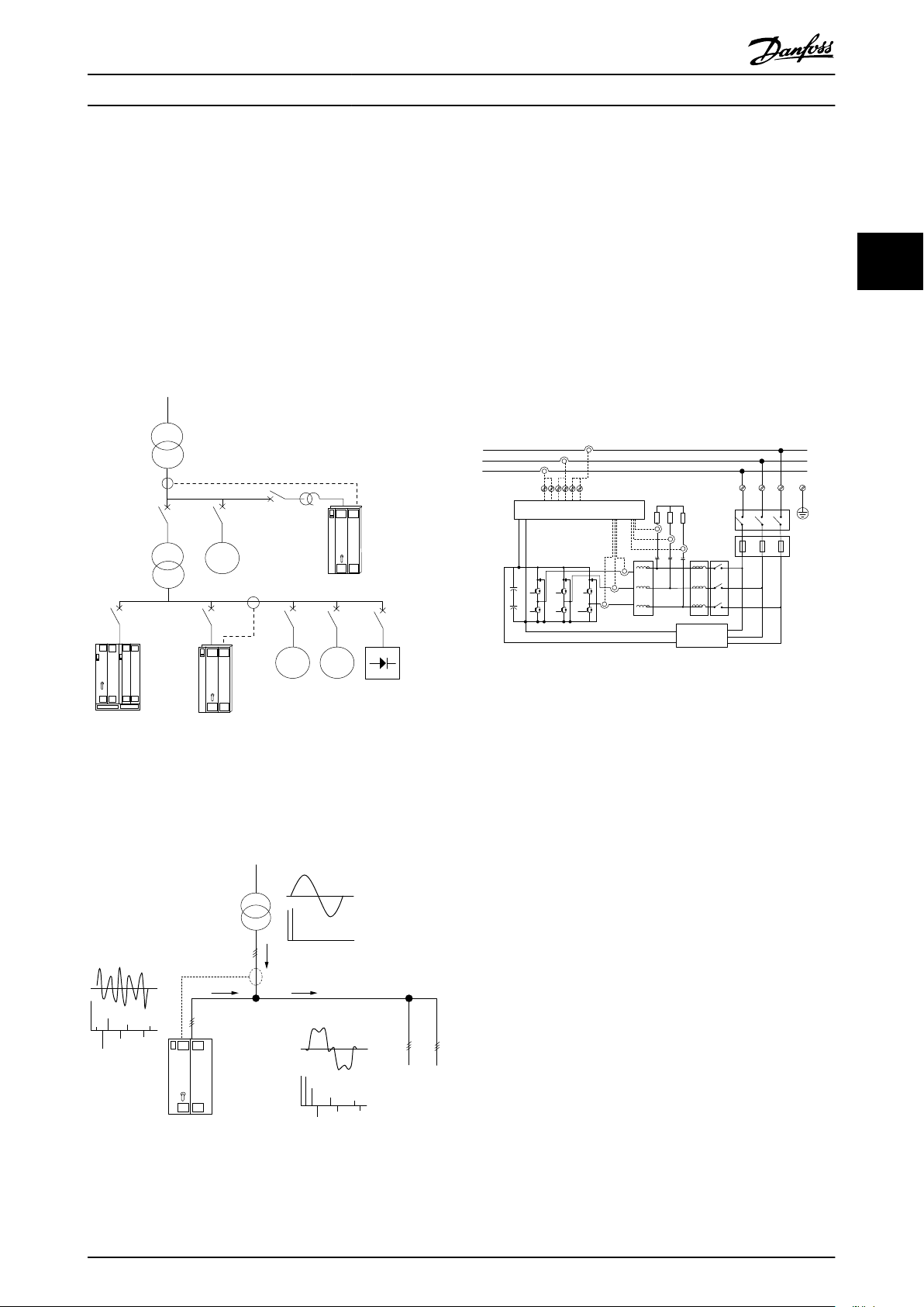
3.1.1 Working Principle
VLT® Active Filter AAF00x is a device for harmonic current
mitigation and reactive current compensation. The unit is
designed for installation in various systems and
applications as centrally installed filter(s) or combined with
a VLT frequency converter as a packaged low harmonic
drive solution.
The counter phase signals are generated by setting
different IGBT switches in real time feeding a DC-voltage
into the grid. The compensated current waveform is
smoothened via a built-in LCL filter making sure that the
IGBT switching frequency and DC-component is not
imposed to the grid. The filter is able to operate on
generator or transformer supply and is able to reduce
individual motor, non-linear loads or mixed loads. All
nonlinear-loads (diode feed loads) must hold AC coils to
protect these units against over current of the input
diodes.
3
3
The active shunt filter monitor all three phase line currents
and process the measured current signal via a digital
signal processor system. The filter then compensates by
actively imposing signals in counter phase to the
unwanted elements of the current.
The factory settings allow for fast start-up but dedicated
programming is possible through the local user control
panel LCP allowing adaptation to more demanding
applications.
The filter allows either overall or selective harmonic
compensation modes. In overall compensation mode all
harmonics will be reduced towards zero. The filter will in
this operation mode also balance out the load to reduce
uneven load distribution between the three phases. The
steady state performance will allow compensate of
harmonics until 40th order but the ultra-quick current
injection allow the filter also to compensate flicker and
other quick and short term phenomenon. In selective
mode the filter allows the user to program acceptable
individual harmonic levels between 5th and 25th order.
The filter will in selective mode not reduce even harmonic
orders nor triplings and will not support phase load
balancing and flicker reduction.
Beside the harmonic compensation mode the filter also
allow the user to program the filter priority from either
reactive current or harmonic compensation. If harmonic
compensation is chosen as the 1st priority, the filter will
use needed current for harmonic reduction and use energy
for reactive current correction only if excessive energy is at
hand. The filter will automatically and continuously assign
energy between 1st and 2nd priority to provide highest
MG.90.V2.02 - VLT® is a registered Danfoss trademark 7

Introduction to VLT Active ... VLT Active Filter AAF 00x
3
possible mitigation of both reactive and harmonic
compensation. This reassures that the true power factor is
continuously optimized and that highest possible
utilization of the supply transformer current is secured.
Filter LCP give user a friendly programming structure and
allow multiple readouts on the LCP. Some read outs are
calculated and approximated values and consequently
cannot be weighted up against readout of a power quality
analyser due to different sample rates and harmonic order
content.
It is not possible to overload the active filter due to the
self protection circuitry that automatically reduces the
compensated current to a level where the filter is at a
stable temperature condition. In case the mitigation
demand is higher then the filter rating the filter will
compensate to the best of it ability and leave remaining
harmonics or reactive currents unaffected.
The active filter is as standard equipped with a RFI filter
fulfilling EMC industrial (second) environment standard
IEC55011 Class A2 equal category C3 of IEC61800-3.
Filter Configurator
3.1.2
Language package 3
English, German, Slovenian, Bulgarian, Serbian, Romanian,
Hungarian, Czech and Russian.
Language package 4
English, German, Spanish, English US, Greek, Brazilian
Portuguese, Turkish and Polish.
To order filters with a different language package, please
contact your local sales office.
It is possible to design an Active Filter according to the
application requirements by using the ordering number
system. For the VLT Active Filter AAF 00x Series, you can
order standard filters and filters with integral options by
sending a type code string describing the product to the
local Danfoss sales office, i.e.:
AAF 00XA190T4E21H2xGCXXXSXXXXAxBXCFXXXDx
The meaning of the characters in the string can be located
in the following pages containing the ordering numbers
and option settings. In the example above a standard 190A
Active Filter is chosen in an IP21 enclosure for a 380-480V
net. From the Internet based configurator, you can
configure the right filter for the right application and
generate the type code string. The configurator will
automatically generate an eight-digit sales number to be
delivered to your local sales office. Furthermore, you can
establish a project list with several products and send it to
a Danfoss sales representative. The configurator can be
found on the global Internet site: www.danfoss.com/drives.
Filters will automatically be delivered with a language
package relevant to the region from which it is ordered.
Four regional language packages cover the following
languages:
Language package 1
English, German, French, Danish, Dutch, Spanish, Swedish,
Italian and Finnish.
Language package 2
English, German, Chinese, Korean, Japanese, Thai,
Traditional Chinese and Bahasa Indonesian.
8 MG.90.V2.02 - VLT® is a registered Danfoss trademark
130BB504.10
1 2 3 4 5 6 7 8 9 10 11 12 13 14 15 16 17 18 19 20 21 22 23 24 25 26 27 28 29 30 31 32 33 34 35 36 37 38 39
A FA x0 0 A T 4 E H x G C x x x x x x x B x C x x x x xDAS
Introduction to VLT Active ... VLT Active Filter AAF 00x
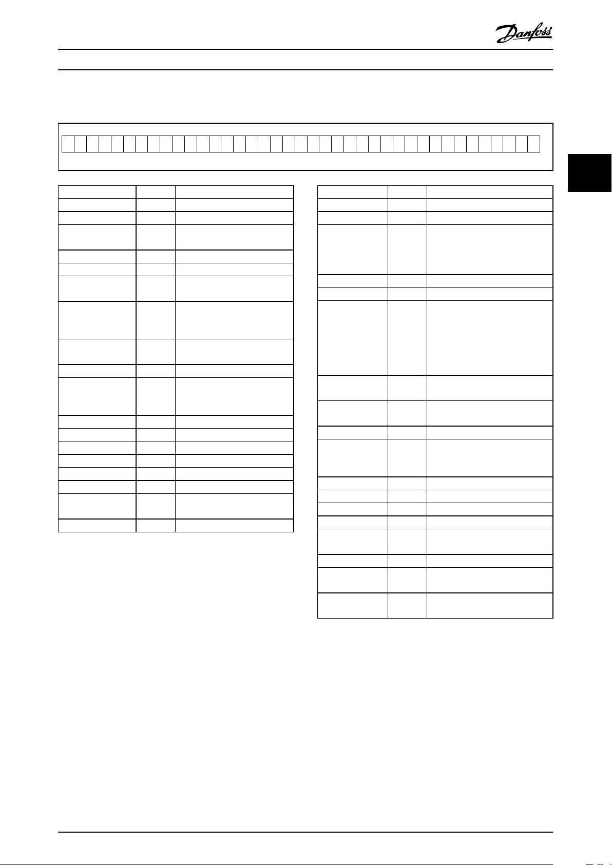
3.1.3 Ordering Form type code
Possible choice
Product groups 1-3 AAF
Series 4-6 005
Current rating 7-10 A190: 190Amp
A250: 250Amp
Phases 11 T: Three Phases
Mains Voltage 12 4: 380-480V AC
enclosure 13-15 E21: IP21/Nema Type1
ESH: IP54 hybrid
RFI filter 16-17 H2: RFI filter, Class A2
(standard)
H4: RFI filter, Class A1 (optional)
Display (LCP) 19 G: Graphical Local Control Panel
(LCP)
Coating PCB 20 C: Coated PCB
Mains option 21 X: No mains option
3: Mains disconnect and fuse
7: Fuse
Adaptation A 22 Reserved
Adaptation B 23 Reserved
Software release 24-27 Reserved
Software language 28 Reserved
A options 29-30 AX: No A option
B options 31-32 BX: No B option
C-option configuration
D options 38-39 DX: No Options
33-37 CFxxx: CO-option occupied with
Active Filter control card
Product groups 1-3 AAF
Series 4-6 006
Current rating 7-10 A190: 190Amp
Phases 11 T: Three Phases
Mains Voltage 12 4: 380-480V AC
enclosure 13-15 E21: IP21/Nema Type1
RFI filter 16-17 H2: RFI filter, Class A2 (standard)
Display (LCP) 19 G: Graphical Local Control Panel
Coating PCB 20 C: Coated PCB
Mains option 21 X: No mains option
Adaptation A 22 Reserved
Adaptation B 23 Reserved
Software release 24-27 Reserved
Software language 28 Reserved
A options 29-30 AQ: MCA-122 Modbus TCP
B options 31-32 BX: No B option
C-option configuration
D options 38-39 DO: 24V backup
Possible choice
A250: 250Amp
A310: 310Amp
A400: 400 Amp
E54: IP54/Nema Type 12
E2M: IP21/Nema Type 1 with
mains shield
E5M: IP54/Nema Type 12 with
mains shield
H4: RFI filter, Class A1 (optional)
(LCP)
3: Mains disconnect and fuse
7: Fuse
AX: No A option
33-37 CFxxx: CO-option occupied with
Active Filter control card
DX: No Options
3
3
MG.90.V2.02 - VLT® is a registered Danfoss trademark 9
K L
K L
K L
L1
L2
L3
92
L2
91
L1
93
L3
95
6
5
4
3
2
1
CTs
130BB720.11
How to Install VLT Active Filter AAF 00x
4 How to Install
4.1 How to Get Started
This chapter covers mechanical and electrical installations
to and from power terminals and control card terminals.
44
4.1.1 How to Get Started
The Active Filter is designed to achieve a quick and EMCcorrect installation by following the steps described below.
WARNING
Read the safety instructions before installing the unit.
Failure to follow recommendations could result in death or
serious injury.
Mechanical Installation
Mechanical mounting
•
Electrical Installation
Connection to Mains and Protecting Earth
•
CT connection and cables
•
Fuses and circuit breakers
•
Control terminals - cables
•
Quick Setup
Local Control Panel of filter
•
Programming
•
4.2 Pre-installation
4.2.1 Planning the Installation Site
NOTE
Before performing the installation it is important to plan
the installation of the Filter. Neglecting this may result in
extra work during and after installation.
Select the best possible operation site by considering the
following (see details on the following pages):
Ambient temperature conditions
•
Altitude at installation point
•
Installation and compensation method
•
How to cool the unit
•
Position of the Active Filter
•
CT installation point and possibility to reuse
•
existing CTs
Cable routing and EMI conditions
•
Ensure the power source supplies the correct
•
voltage and frequency
If the unit is without built-in fuses, ensure that
•
the external fuses are rated correctly.
Receiving the Active Filter
4.2.2
When receiving the unit please make sure that the
packaging is intact, and be aware of any damage that
might have occurred to the unit during transport. In case
damage has occurred, contact immediately the shipping
company to claim the damage.
NOTE
Damaged packaging can indicate a too rough transportation which might have resulted in inside failures of the
unit. Even though the unit from the outside seems to be
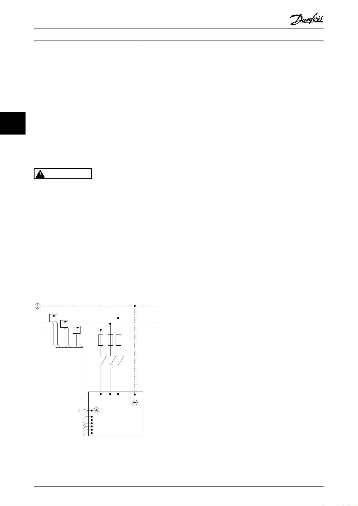
Illustration 4.1 Diagram showing basic installation including
mains and CTs.
10 MG.90.V2.02 - VLT® is a registered Danfoss trademark
intact make sure to claim the damage
4.2.3 Transportation and Unpacking
Before unpacking the Active Filter it is recommended that
it is located as close as possible to the final installation
site. Keep the filter on the pallet and boxed, as long as
possible to avoid scratches and dents.
130BB494.10
130BB642.10
How to Install VLT Active Filter AAF 00x
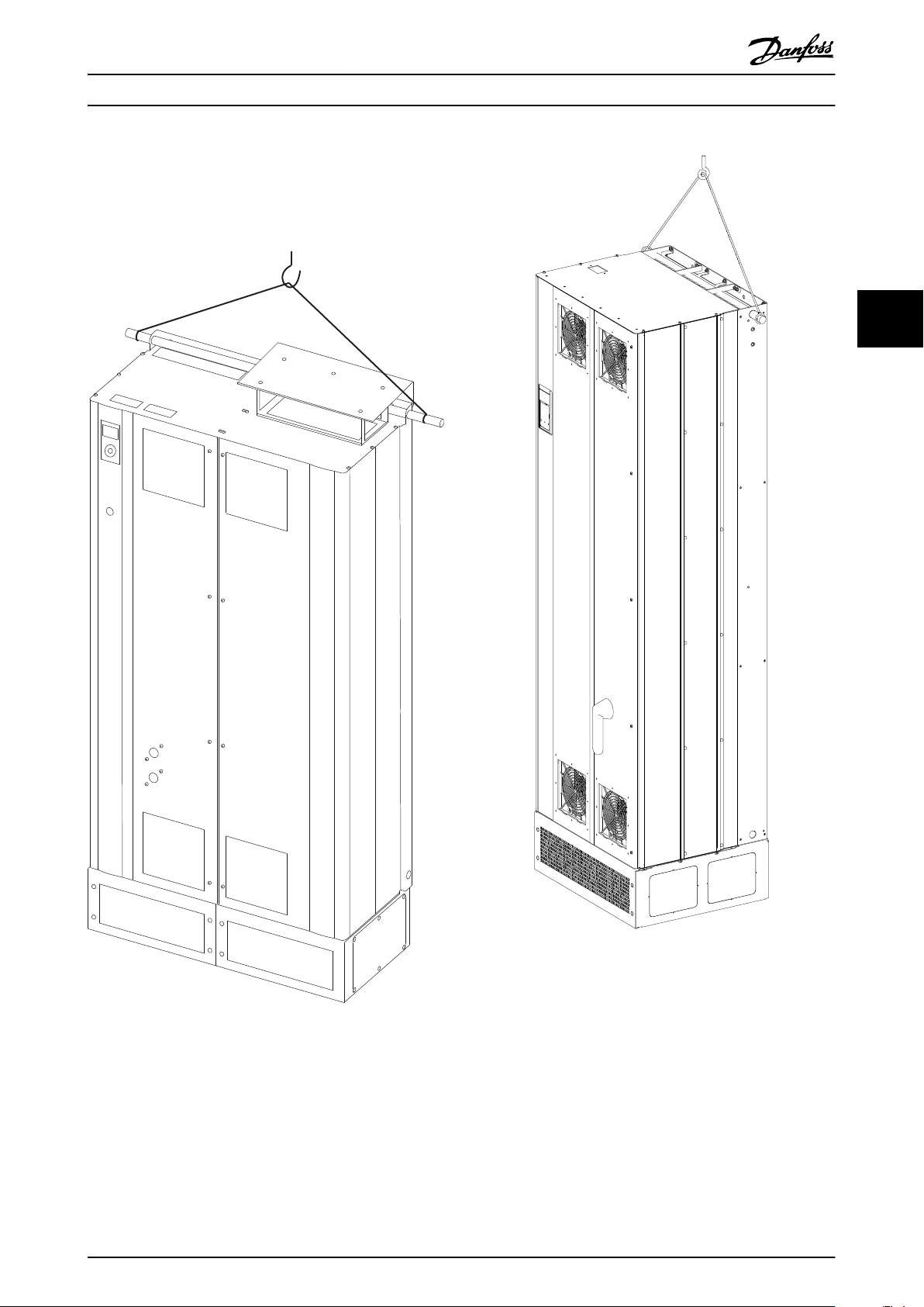
4.2.4 Lifting
Always lift the unit in the dedicated lifting eyes. Use a bar
to avoid bending the lifting holes.
4 4
Illustration 4.2 Recommended Lifting Method for AAF 005,
Frame Sizes D9 and E7.
Illustration 4.3 Recommended Lifting Method for AAF 006,
Frame Sizes D13 and E9.
NOTE
The lifting bar must be able to handle the weight of the unit. See Mechanical Dimensions for the weight of the different
frame sizes. Maximum diameter for bar is 25mm (1 inch). The angle from the top of the unit to the lifting cable should be
60° or greater.
MG.90.V2.02 - VLT® is a registered Danfoss trademark 11
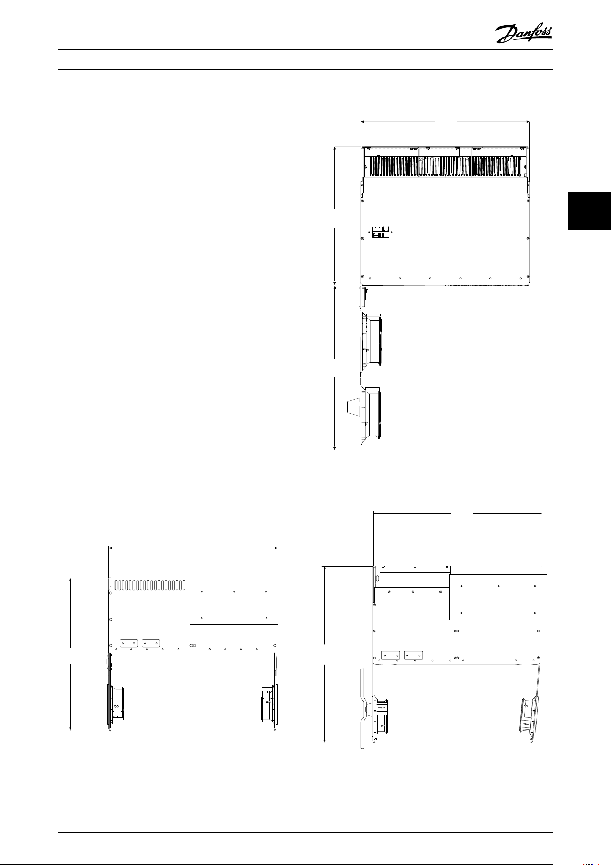
1733,6
[68]
1553,4
[61]
1853,6
[73]
200.0
[8]
377,8
[15]
130BB495.10
840
How to Install VLT Active Filter AAF 00x
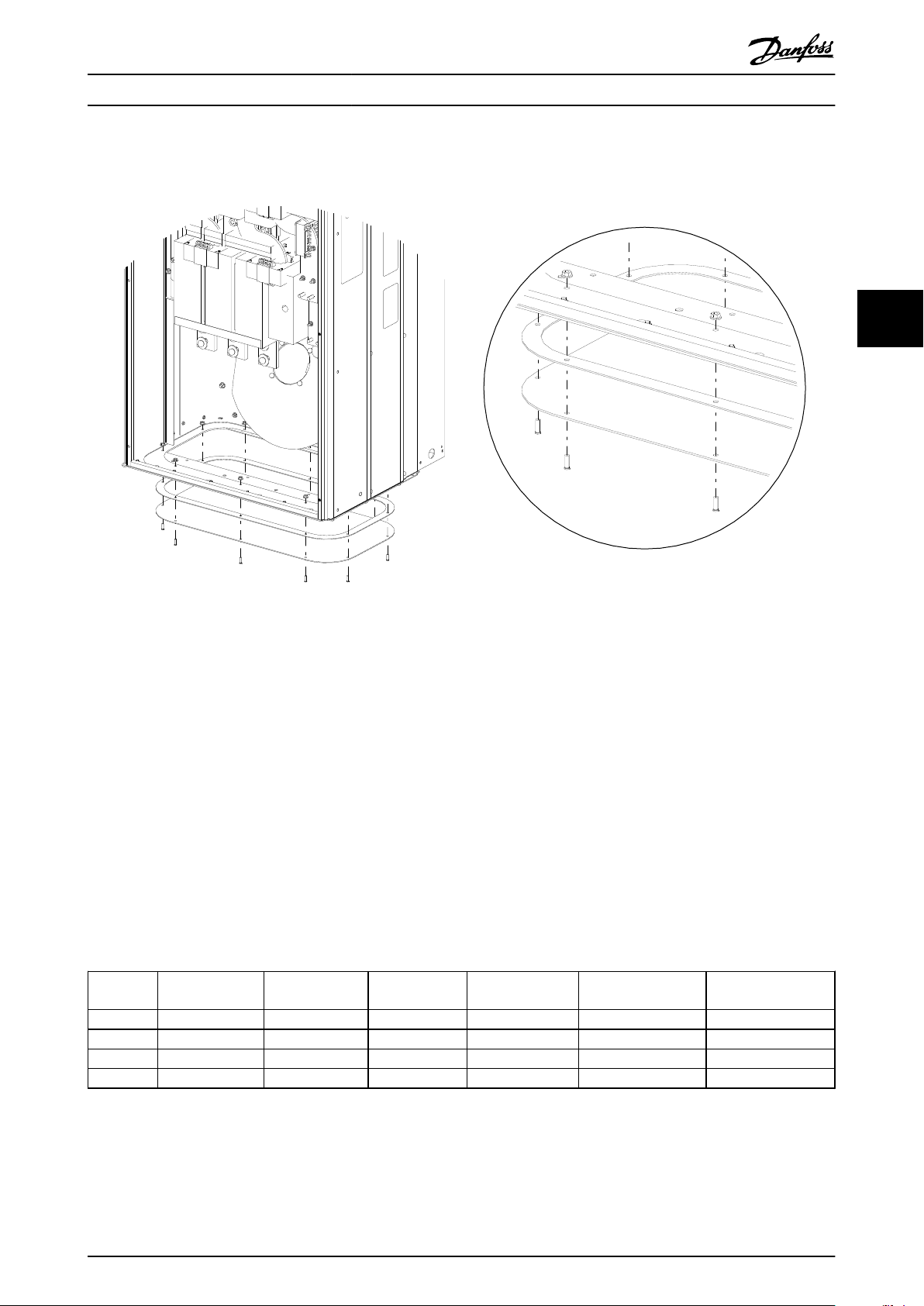
NOTE
Note the plinth is provided in the same packaging as the filter, but is not always attached to frame during shipment. The
plinth is required to allow airflow to the unit to provide proper cooling. The plinth of the D and E-frames filters should be
mounted before the unit is lifted to its final position.
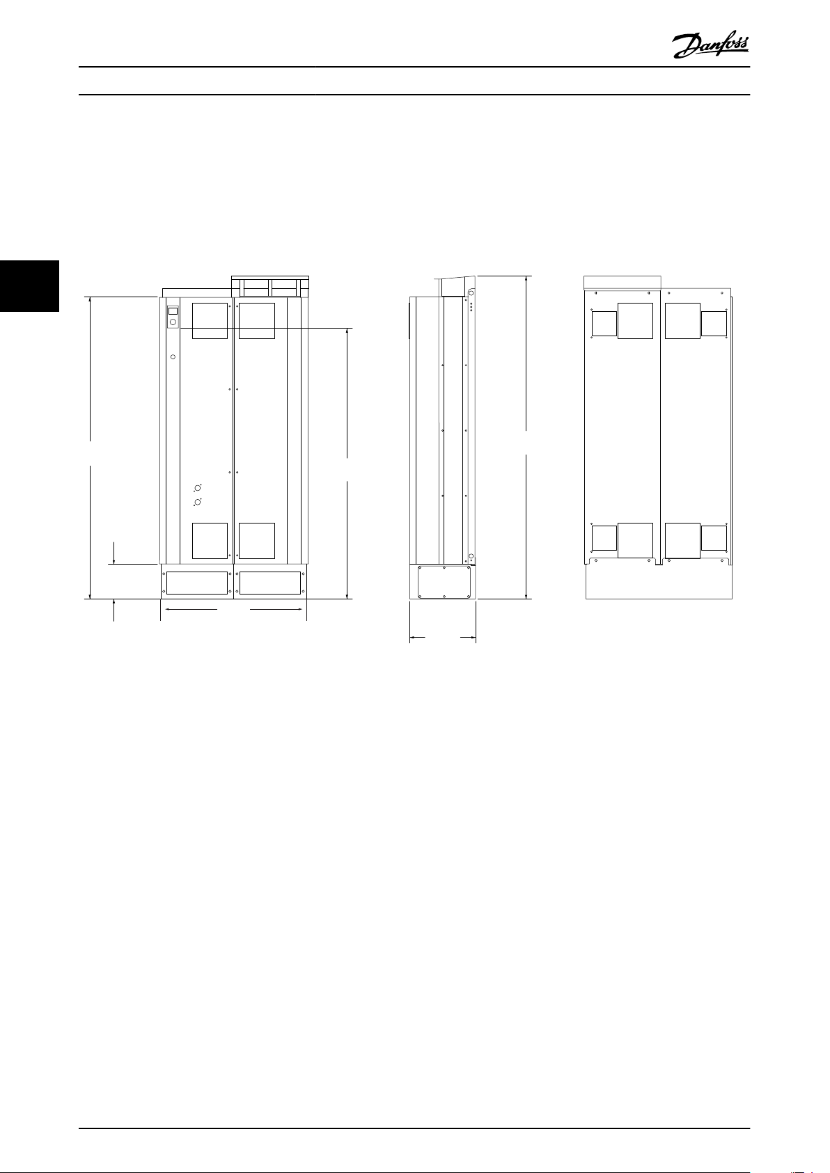
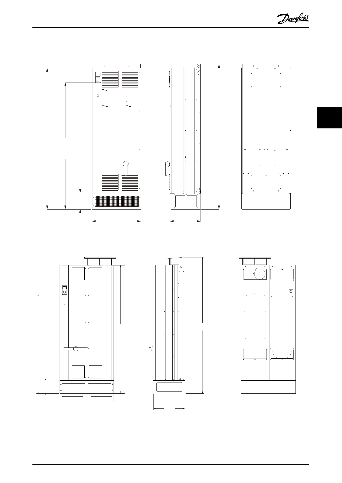
4.2.5 Mechanical Dimensions
44
Illustration 4.4 Frame size D9, AAF05
12 MG.90.V2.02 - VLT® is a registered Danfoss trademark
1732
[68.2]
1553
[61.1]
200
[7.9]
602
[23.7]
1781
[70.1]
378
[14.9]
130BB961.10
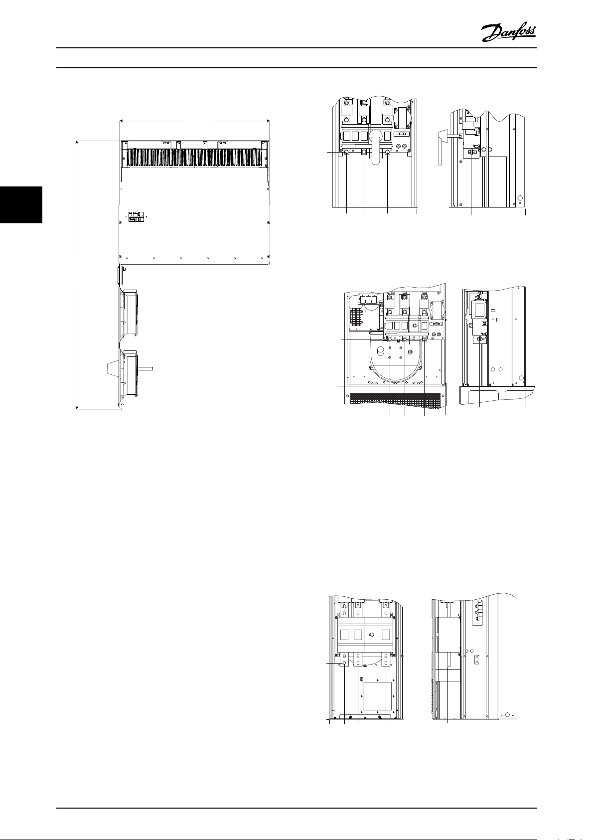
1549,9
[61]
2119,8
[83]
159,2
[8]
493,5
[19]
2000,1
[79]
130BB496.10
840
How to Install VLT Active Filter AAF 00x
4 4
Illustration 4.5 Frame size D13, AAF06
Illustration 4.6 Frame size E7, AAF05
MG.90.V2.02 - VLT® is a registered Danfoss trademark 13
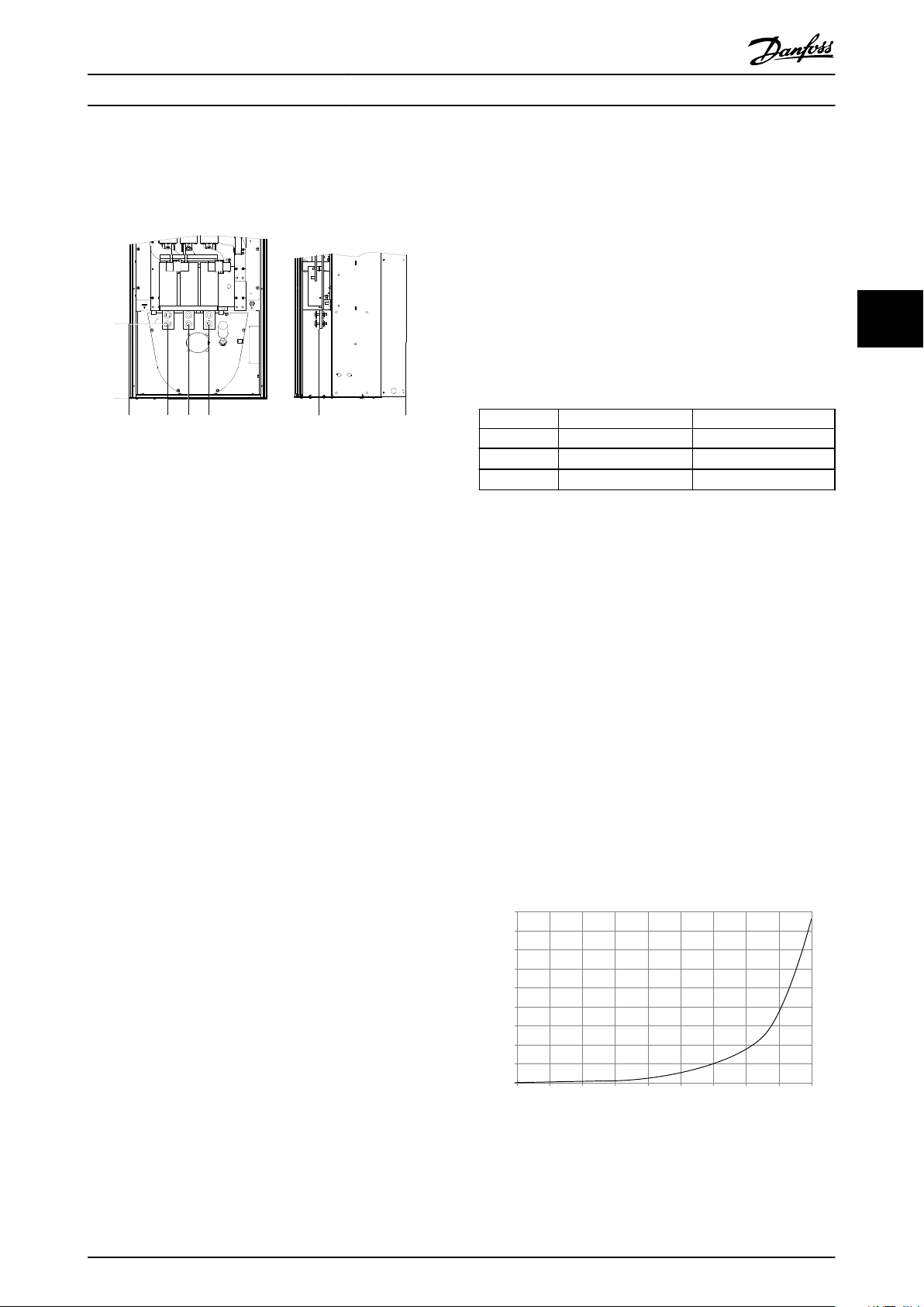
2004.50 mm
1491.35 mm
493.23 mm
2000
[78,78]
195
[7,68]
491,19
[19,43]
130BB644.10
1498
[59,06]
600
How to Install VLT Active Filter AAF 00x
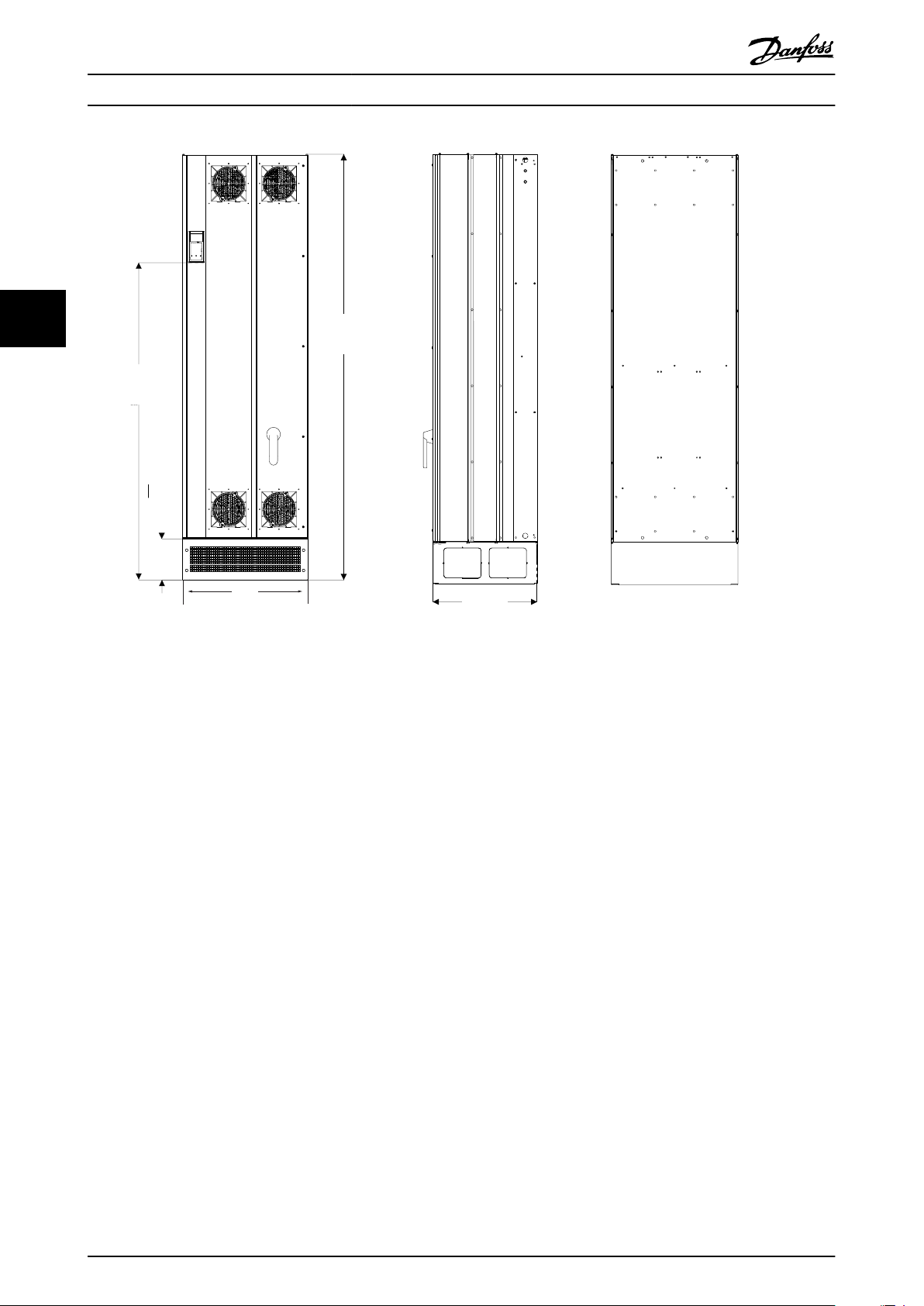
44
Illustration 4.7 Frame size E9, AAF06
14 MG.90.V2.02 - VLT® is a registered Danfoss trademark
How to Install VLT Active Filter AAF 00x
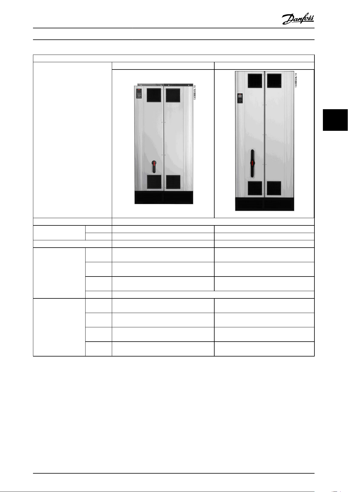
Mechanical dimensions and rated power
Frame size D9 E7
4 4
Version AAF05 AAF05
enclosure protection
Nominal current rate 190A 250A
Shipping Dimensions Height
Filter Dimensions Height
IP 21/54 hybrid 21/54 hybrid
NEMA Type 1 Type 1
(mm)
Width
(mm)
Depth
(mm)
Weight (kg) 400 450
(mm)
Width
(mm)
Depth
(mm)
Max
Weight (kg)
1852 2111
1118 1118
947 947
1732 2000
840 840
380 494
293 352
MG.90.V2.02 - VLT® is a registered Danfoss trademark 15
130BB646.10
130BB645.10
How to Install VLT Active Filter AAF 00x
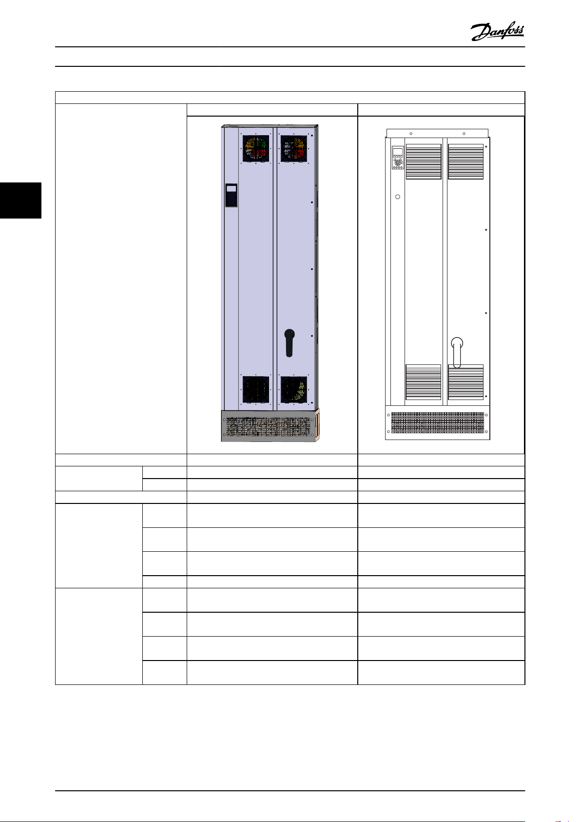
Mechanical dimensions and rated power
Frame size D13 E9
44
Version AAF06 AAF06
enclosure protection
Nominal current rate 190A 250, 310, 400A
Shipping Dimensions Height
Filter Dimensions Height
IP 21/54 21/54
NEMA Type 1/12 Type 1/12
(mm)
Width
(mm)
Depth
(mm)
Weight (kg) 340 500
(mm)
Width
(mm)
Depth
(mm)
Max
Weight (kg)
750 864
737 737
1943 2203
1740 2000
600 600
380 494
293 458
16 MG.90.V2.02 - VLT® is a registered Danfoss trademark
849.1
[33.4]
3x771.0
[30.4]
130BB497.10
599.60 mm
600
[23]
380
[15]
130BB721.11
600
[23]
849,0
[33]
889,1
[35]
130BB498.10
How to Install VLT Active Filter AAF 00x
4.3 Mechanical Installation
Preparation of the mechanical installation of the filter must
be done carefully to ensure a proper result and to avoid
additional work during installation. Start taking a close
look at the mechanical drawings in 4.2.5 Mechanical
Dimensions to become familiar with the space demands.
4.3.1 Tools Needed
To perform the mechanical installation the following tools
are needed:
Drill with 10 or 12mm drill
•
Tape measure
•
Screw driver
•
Wrench with relevant metric sockets (7-17mm)
•
Extensions to wrench
•
Sheet metal punch for conduits or cable glands
•
Lifting bar to lift the unit (rod or tube max. Ø
•
25mm (1 inch), able to lift minimum 1000kg).
Crane other lifting aid to place the unit in
•
position
Torx T50 tool
•
4 4
General Considerations
4.3.2
Space
Ensure proper space above and below the unit to allow
airflow and cable access. In addition space in front of the
unit must be considered to enable opening of the door of
the panel.
Illustration 4.9 Space in front of IP21/IP54 enclosure type, frame
size D13 .
Illustration 4.8 Space in front of IP21/IP54 enclosure type, frame
size D9 .
MG.90.V2.02 - VLT® is a registered Danfoss trademark 17
Illustration 4.10 Space in front of IP21/IP54 enclosure type, frame
size E7.
597.00 mm
1068.91 mm
1069
[42,08]
597
[23,50]
130BB722.10
130BB425.10
0
[.0]
0
[.0]
0
[.0]
3x277,1
[10.9]
239,6
147,7
[10.6]
[5.8]
263,6
[10.4]
35,6
[13.8]
R/L1 91 T/L3 93S/L
3X 276,87
[10.9]
0
[.0]
267,4
[10.5]
0
[.0]
120,8
[4.8]
236,8
[9.3]
0
[.0]
324,8
[12.8]
130BB723.10
130BB431.10
332.5
[13.1]
.0
[.0]
.0
[.0]
.0
[.0]
407.5
[16.0]
332.0
[13.1]
88.0
[3.5]
168.0
[6.6]
How to Install VLT Active Filter AAF 00x
44
Illustration 4.12 Terminal Location of Frame D9
Illustration 4.11 Space in front of IP21/IP54 enclosure type, frame
size E9.
Wire access
Ensure that proper cable access is present including
necessary bending allowance.
NOTE
All cable lugs/ shoes must mount within the width of the
terminal bus bar.
4.3.3 Terminal Locations - Frame size D
Consider the following position of the terminals when
designing for cables access.
Illustration 4.13 Terminal Location of Frame D13
Be aware that the power cables are heavy and hard to
bend. Consider the optimum position of the unit for
ensuring easy installation of the cables.
Terminal Locations - Frame size E
4.3.4
Take the following position of the terminals into consideration when designing the cable access.
Illustration 4.14 Terminal Location of Frame E7
18 MG.90.V2.02 - VLT® is a registered Danfoss trademark
323,9
[12,8]
0
[0]
0
[0]
0
[0]
380,7
[15]
169,7
[6,6]
258,7
[10,2]
348,7
[13,7]
130BB724.10
90
80
70
60
50
40
30
20
10
0
0 0.5 4.9 13 27.3 45.9 66 89.3 115.7 147
(%)
(Pa)
Pressure Increase
Filter Derating
130BB932.10
How to Install VLT Active Filter AAF 00x
NOTE
A door fan(s) is required on the enclosure to remove the
heat losses not contained in the backchannel of the unit
and any additional losses generated from other
components installed inside the enclosure. The total
required air flow must be calculated so that the
appropriate fans can be selected. Some enclosure
manufacturers offer software for performing the
calculations (i.e. Rittal Therm software).
Airflow
The necessary airflow over the heat sink must be secured.
The flow rate is shown below.
Frame size D13/D9 E9, E7
Illustration 4.15 Terminal Location of Frame E9
Door fan
Heatsink
4 4
Enclosure IP21 / IP54 IP21/54
340m3/h (200 cfm) 340m3/h (200 cfm)
765m3/h (450 cfm) 1230m3/h (725 cfm)
NOTE
Note that the power cables are heavy and difficult to
bend. Consider the optimum position of the unit for
ensuring easy installation of the cables.
Each terminal allows use of up to 4 cables with cable lugs
or use of standard box lug. Earth is connected to relevant
termination point in the unit.
4.3.5 Cooling and Airflow
Cooling
Cooling can be obtained in different ways, by using the
cooling ducts in the bottom and the top of the unit, by
taking air in the back of the unit or by combining the
cooling possibilities.
Back cooling
The design of the active filter is built on a backchannel
cooling system where 85% of all heat is ducted via an IP54
segregated backchannel. This reduces the needed airflow
inside the enclosure and ensures less moist and dust
ventilation across vital components.
The backchannel air is normally ventilated via the plint
inlet and ducted out the top of the enclosure. The design
of the backchannel does, however, also allow air to be
taken from outside the control room and dusted back out
again. This is supported to ease stress on the control room
air conditioner and so conserve energy. To support back
wall inlet, the unit air inlet has to be blocked via an
optional cover and the air outlet ducted via an optional
top duct.
Table 4.1 Heatsink Air Flow
NOTE
For the active filter, the fan runs for the following reasons:
1. Active filter running
2. Specific heatsink temperature exceeded (power
size dependent)
3. Specific Power Card ambient temperature
exceeded (power size dependent)
4. Specific Control Card ambient temperature
exceeded
Once the fan is started it will run for minimum 10 minutes.
External ducts
If additional duct work is added externally to the Rittal
cabinet the pressure drop in the ducting must be
calculated. Use the charts below to derate the unit
according to the pressure drop.
MG.90.V2.02 - VLT® is a registered Danfoss trademark 19
Illustration 4.16 D frame Derating vs. Pressure Change
Air flow: 450 cfm (765 m3/h)
90
80
70
60
50
40
30
20
10
0
(%)
Filter Derating
0 0 0.1 3.6 9.8 21.5 43.4 76 237.5 278.9
(Pa)
Pressure Change
130BB933.10
147.1
246,0
[10]
20,0
[1]
380,0
[15]
419,7
[17]
55,9
[2]
2X
130BB499.10
560
[22.0]
350
[13.8]
20
[.8]
2X370
[14.6]
2X200
[7.9]
60
[2.4]
69,5
[2.74]
70,4
[2.77]
203
[8.0]
246
[9.7]
2X113
[4.4]
60
[2.3]
115
[4.5]
2X223
[8.8]
70
[2.8]
130BB963.10
130BB500.10
800,0
[32]
361,7
[14]
55,9
[2]
380,0
[15]
20,0
[1]
2X 370
[15]
60
[2.5]
2X 200
[8]
2X 112.75
[4.5]
2X 222.75
[9]
74.6
[3]
350
[14]
70
[3]
202.75
[8]
84.6
[3.5]
560
[22]
361.7
[14.5]
70.4
[3]
20
[1]
130BB734.10
5.10
[.2]
How to Install VLT Active Filter AAF 00x
44
Illustration 4.17 E frame Derating vs. Pressure Change
Air flow: 725 cfm (1230m3/h)
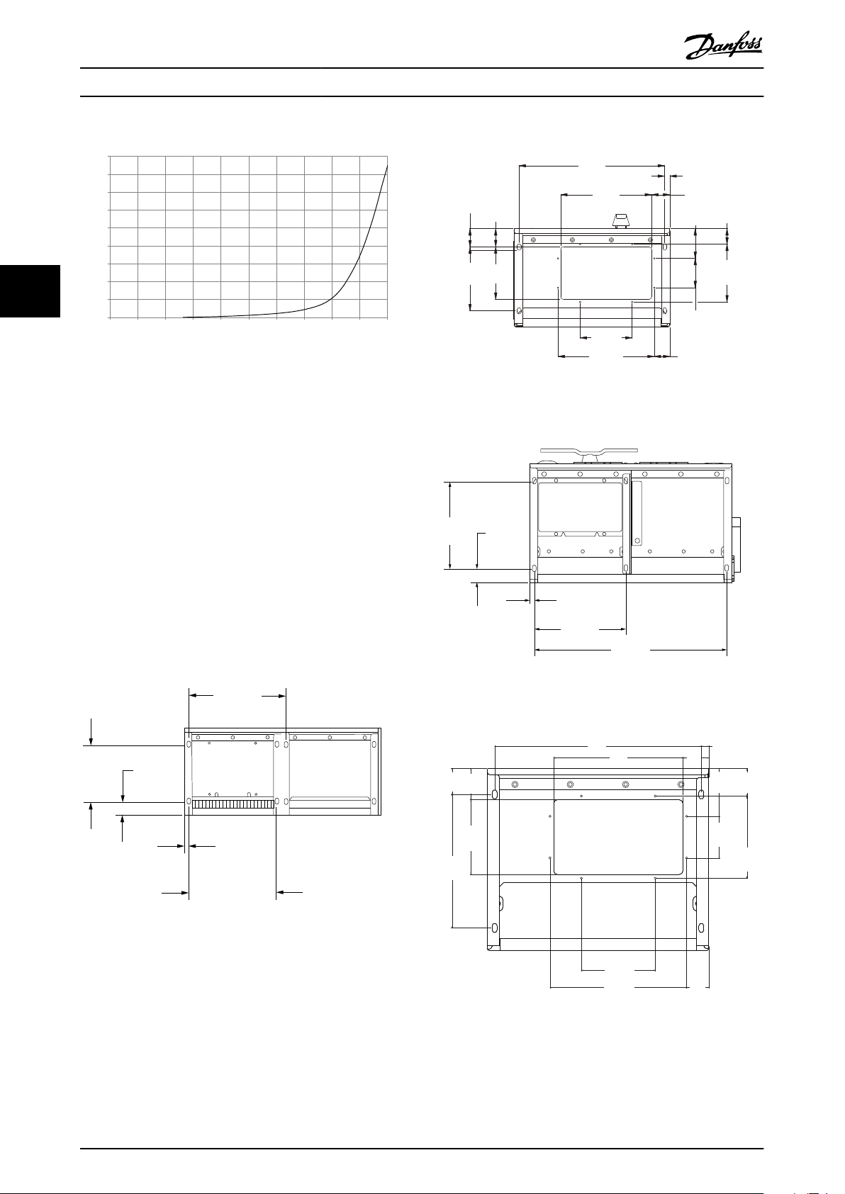
Illustration 4.19 Frame Size D13
Gland/Conduit Entry - IP21 (NEMA 1)
4.3.6
and IP54 (NEMA12)
Cables are connected through the gland plate from the
bottom. Remove the plate and plan where to place the
entry for the glands or conduits. Prepare holes in the
marked area on the drawing.
NOTE
The gland plate must be fitted to the active filter to ensure
the specified protection degree, as well as ensuring proper
cooling of the unit. If the gland plate is not mounted, the
unit may trip on Alarm 69, Pwr. Card Temp
Cable entries viewed from the bottom of the filter
Illustration 4.18 Frame Size D9
20 MG.90.V2.02 - VLT® is a registered Danfoss trademark
Illustration 4.20 Frame Size E7
Illustration 4.21 Frame Size E9
130BB736.10
How to Install VLT Active Filter AAF 00x
4 4
Illustration 4.22 Mounting of bottom plate, E
The bottom plate of the E frame can be mounted from either in- or outside of the enclosure, allowing flexibility in the
installation process, i.e. if mounted from the bottom the glands and cables can be mounted before the unit is placed on the
pedestal.
4.4
Field Installation of Options
4.4.1 Installation of Input Plate Options
This section is for the field installation of input option kits available for Active Filters.
Do not attempt to remove RFI filters from input plates. Damage may occur to RFI filters if they are removed from the input
plate.
D9 177G2348 177G2344 177G2346 177G2347 177G2343 177G2345
E7 176F0253 176F0255 176F0257 176F0258 176F0260
D13 177G2348 177G2344 177G2346 177G2347 177G2343 177G2345
E9 176F0253 176F0255 176F0257 176F0258 176F0260
Fuses Disconnect and
Fuse
RFI Fuses & RFI Fuses, RFI &
Disconnect
None
MG.90.V2.02 - VLT® is a registered Danfoss trademark 21
3 Phase
power
input
130BA026.10
91 (L1)
92 (L2)
93 (L3)
95 PE
How to Install VLT Active Filter AAF 00x
4.5 Electrical Installation
4.5.1 Power Connections
Cabling and fusing
NOTE
Cables General
44
All cabling must comply with national and local
regulations on cable cross-sections and ambient
temperature. UL applications require 75 °C copper
conductors. 75° and 90 °C copper conductors are thermally
acceptable for use in non UL applications.
NOTE
If is insufficient to rate the power cable for the filter
current rating alone due to skin and proximity effects.
The power cable connections are situated as shown below.
The mains connection is fitted to the mains switch if this is
included. Dimensioning of cable cross section must be
done in accordance with the filter current rating including
skin and proximity effects, derating and local legislation.
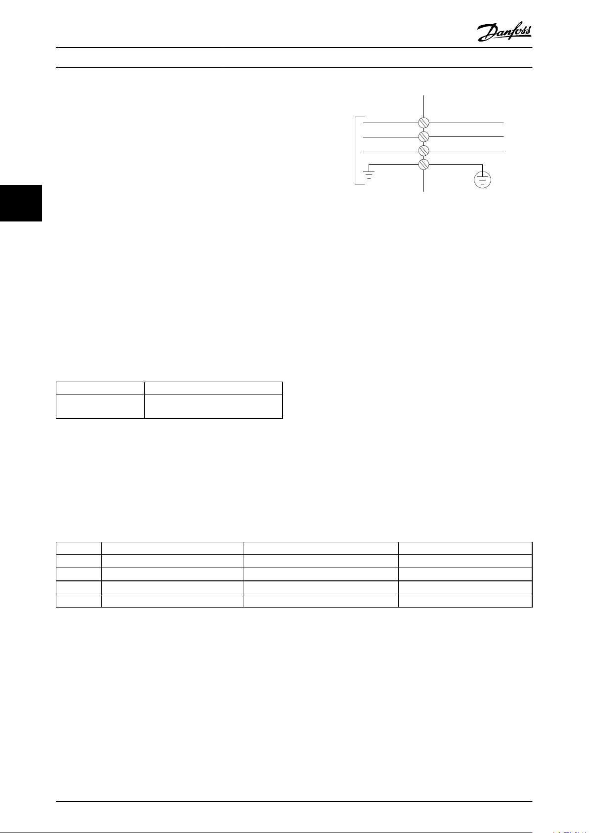
Mains must be connected to terminals 91, 92 and 93. Earth
is connected to the terminal to the right of terminal 93.
Terminal No.
91, 92, 93
94
The conductor is predominantly carrying currents of high
frequencies so the distribution of current is not evenly
dispersed throughout the cross section of the conductor.
This is due to two independent effects known as skin
effect and proximity effect. Both effects make derating
necessary and consequently the mains wire of the Active
Filters have to be rated at a higher current then the filter
rating itself.
Filter
190A
250A
310A
400A
Function
Mains R/L1, S/L2, T/L3
Earth
Min CU wire Min ALU wire Max wire
70mm2 (2/0) 95mm2 (3/0) 2*150mm2 (2*300MCM)
120mm2 (4/0) 150mm2 (300MCM) 4x240mm2 (4x500MCM)
240 mm2 (500MCM) 2*95mm2 (2*3/0) 4x240mm2 (4x500MCM)
2*95mm2 (2*3/0) 2*150mm2 (2*300MCM) 4x240mm2 (8x900MCM)
The required derating is calculated as two separate factors:
one for the skin effect and one for the proximity effect.
The skin factor is depending on frequency of conduct,
cable material and cable dimensions. The proximity effect
is depending on the number of conducts, diameters and
distance between the individual cables.
The optimized mains wire is:
Cupper wires
•
Single conducts
•
Busbars
•
The reason for that is that cupper has lower skin effect
factors then aluminium, busbars have bigger surface area
compared to cables reducing the skin effect factor and
proximity effects of single conducts is negligible.
The following cables specifications take both skin and
proximity effects into account:
Table 4.2 Allowed Active Filter Mains Cable with Typical Cable Manufacturer Data
22 MG.90.V2.02 - VLT® is a registered Danfoss trademark
130BB501.10
8
7
6
5
4
3
1
9
2
How to Install VLT Active Filter AAF 00x
Due to the built-in LCL filter the unit will not feed the main wire with high dU/dt signals. That reduces the radiated
emission through the power cable. Cable screen/shielding can thus be omitted allowing the mains cables to be connected
without considering EMC requirements.
The Active Filter will be able to run at long cable runs. Cable length is limited by the voltage drop. It is advised to keep the
cable lengths to less then 200m.
For protection of the active filter, the recommended fuses must be used or the unit must be with built-in fuses.
Recommended fuses can be seen in the tables of the fuse section. Always ensure that proper fusing is made according to
local regulation.
4 4
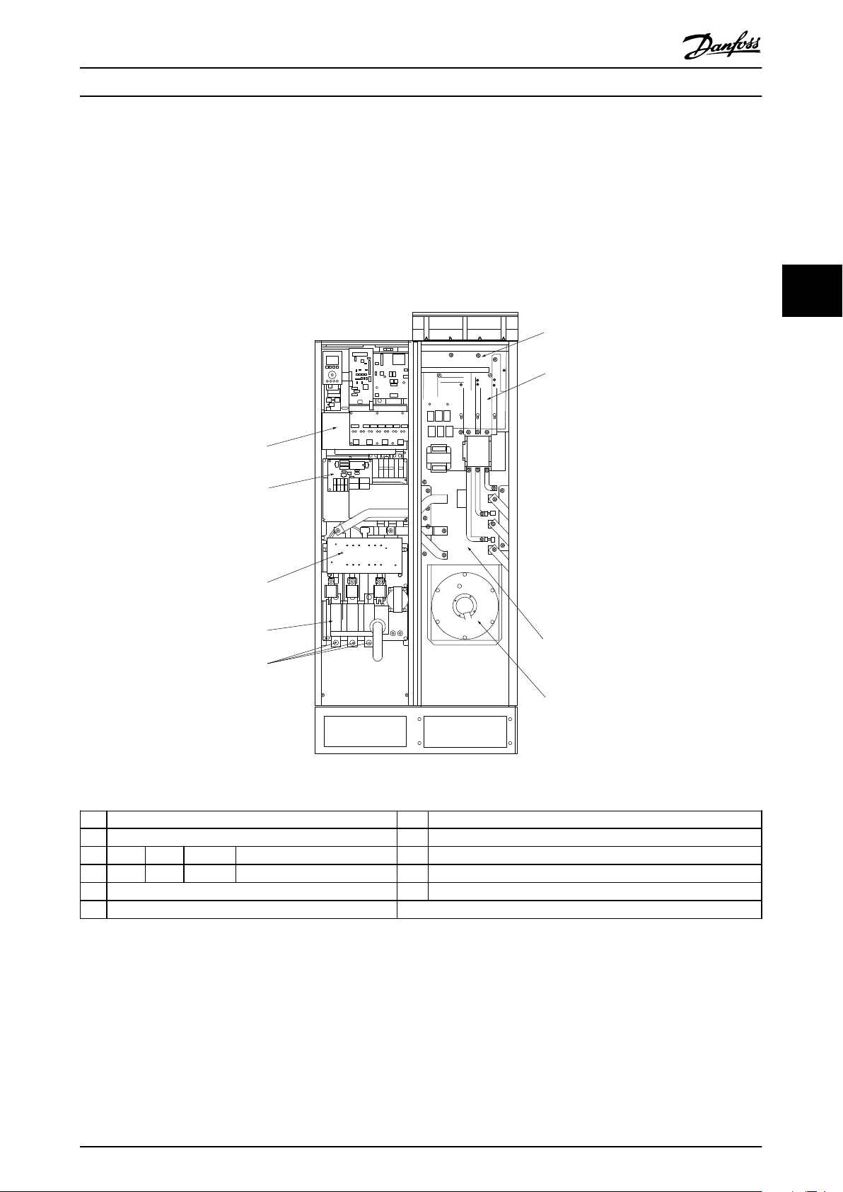
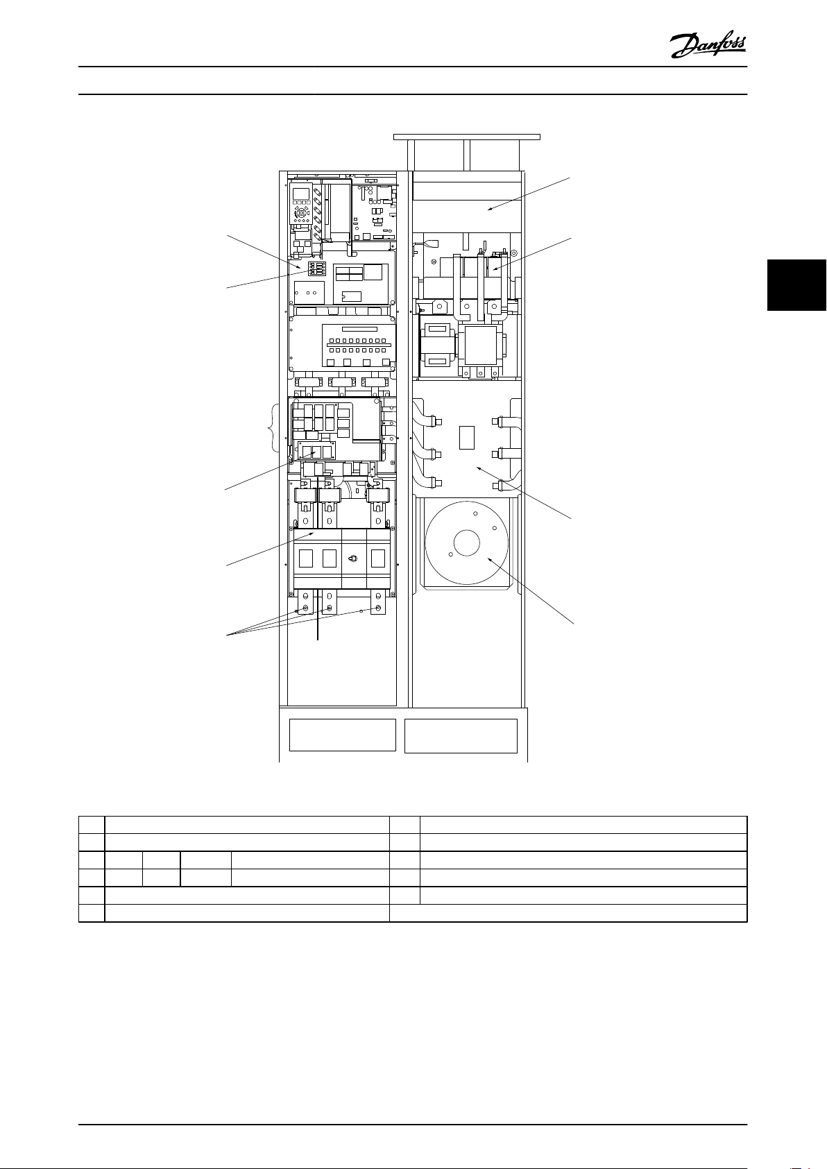
Illustration 4.23 Frame size D9
RFI 5) LCL line reactor
1)
2) Mains wire connection 6) LCL capacitors
R S T 7) LCL filter reactor
L1 L2 L3 8) CT-wire connection point
3) Input plate 9) Fan/ SMPS fuse
4) Backchannel fan
MG.90.V2.02 - VLT® is a registered Danfoss trademark 23
130BB738.11
7
3
2
1
6
8
4
5
10
9
How to Install VLT Active Filter AAF 00x
44
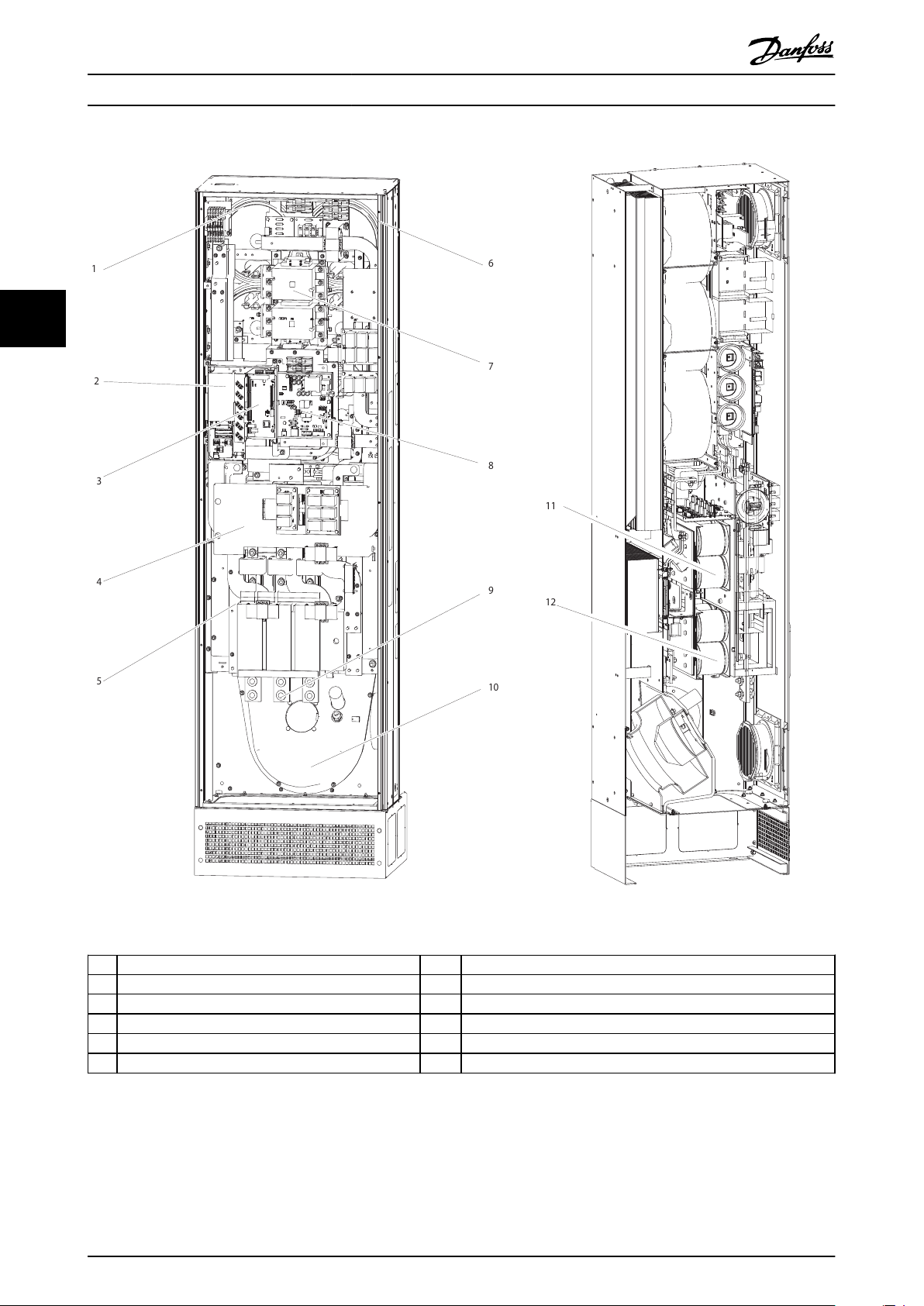
Illustration 4.24 Frame size D13
1)
CT - connection terminal 7) Mains contactor
2) FC card 8) Power card
3) AFC card 9) Mains wire connection
4) RFI (input option plate) 10) Back channel
5) Fuse/disconnect (mains option) 11) LCL circuitry
6) LCL circuitry 12) DC-capacitors
24 MG.90.V2.02 - VLT® is a registered Danfoss trademark
130BB502.10
2
9
1
3
1
8
4
5
6
7
How to Install VLT Active Filter AAF 00x
4 4
Illustration 4.25 Frame size E7
RFI 5) LCL line reactor
1)
2) Mains wire connection 6) LCL capacitors
R S T 7) LCL filter reactor
L1 L2 L3 8) CT-wire connection point
3) Input plate 9) Fan/ SMPS fuse
4) Backchannel fan
MG.90.V2.02 - VLT® is a registered Danfoss trademark 25
10
5
916
4
832
7
12
11
130BB740.10
How to Install VLT Active Filter AAF 00x
44
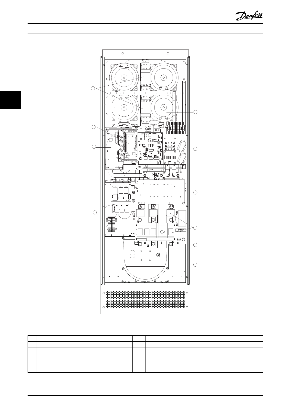
Illustration 4.26 Frames Sizes E9
CT - connection terminal 7) Mains contactor
1)
2) FC card 8) Power card
3) AFC card 9) Mains wire connection
4) RFI (input option plate) 10) Back channel
5) Fuse/disconnect (mains option) 11) LCL circuitry
6) LCL circuitry 12) DC-capacitors
Table 4.3 Frames Sizes D13
26 MG.90.V2.02 - VLT® is a registered Danfoss trademark
EARTH
TERMINALS
130BB739.10
How to Install VLT Active Filter AAF 00x
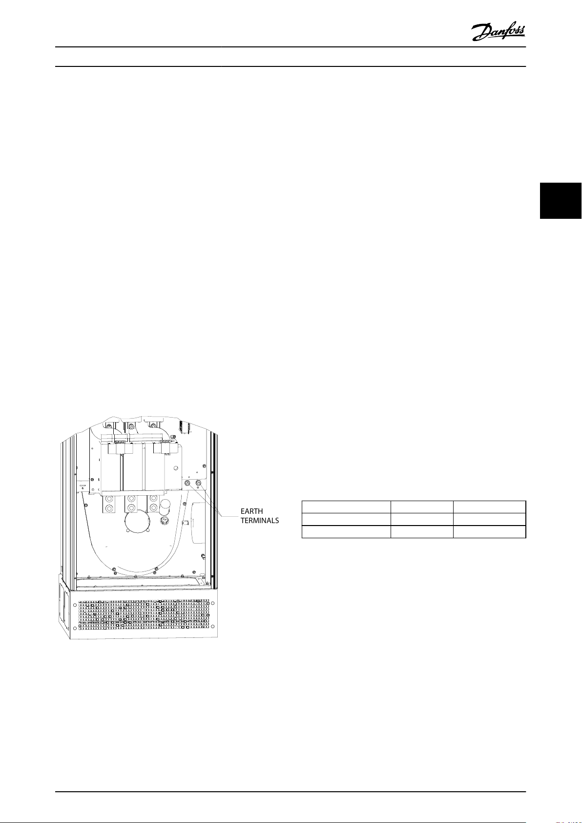
4.5.2 Earthing
The following basic issues need to be considered when
installing an active filter, so as to obtain electromagnetic
compatibility (EMC).
Safety earthing: Please note that the active filter
•
has leakage current and must be earthed
appropriately for safety reasons. Apply local
safety regulations.
High-frequency earthing: Keep the earth wire
•
connections as short as possible.
Connect the different earth systems at the lowest possible
conductor impedance. The lowest possible conductor
impedance is obtained by keeping the conductor as short
as possible and by using the greatest possible surface area.
The metal cabinets of the different devices are mounted
on the cabinet rear plate using the lowest possible HF
impedance. This avoids having different HF voltages for
the individual devices and avoids the risk of radio
interference currents running in connection cables that
may be used between the devices. The radio interference
will have been reduced. In order to obtain a low HF
impedance, use the fastening bolts of the devices as HF
connection to the rear plate. It is necessary to remove
insulating paint or similar from the fastening points.
current. If ELCB relays are used, local regulations must be
observed. To reassure effective protection and unintended
tripping of protective relays, all relays must be suitable for
protection of 3-phase equipment with active current infeed
and for a brief discharge during power-up. It is
recommended to use a type with adjustable trip amplitude
and time characteristics. Select a current sensor with
sensitivity of more then 200mA and not less than 0.1second operation time.
4 4
4.5.4 RFI Switch
Mains supply isolated from earth
If the Active filter is supplied from an isolated mains
source (IT mains, floating delta and grounded delta) or
TT/TN-S mains with grounded leg, the RFI switch is
recommended to be turned off (OFF) 1) via 14-50 RFI Filter
on the unit. For further reference, see IEC 364-3. In OFF,
the internal RFI capacities between the chassis and the
intermediate circuit are cut off to avoid damage to the
intermediate circuit and to reduce the earth capacity
currents (according to IEC 61800-3). Please also refer to the
application note VLT on IT mains, MN.90.CX.02. It is
important to use isolation monitors that are capable for
use together with power electronics (IEC 61557-8).
Illustration 4.27 Example of Earth Terminal Position
Torque
4.5.5
When tightening all electrical connections it is very
important to tighten with the correct torque. Too low or
too high torque results in a bad electrical connection. Use
a torque wrench to ensure correct torque. Below is the
tightening torque required for the mains terminal:
Frame size
D 19Nm M10
E 19Nm M10
Torque Bolt size
Extra Protection (RCD)
4.5.3
ELCB, RCD, GFCI relays or multiple protective earthings are
often used as extra protection, or needed to provide
compliance with local safety regulations. In case of an
earth fault, a DC component may develop in the fault
MG.90.V2.02 - VLT® is a registered Danfoss trademark 27
Nm/in-lbs
130BB741.10
How to Install VLT Active Filter AAF 00x
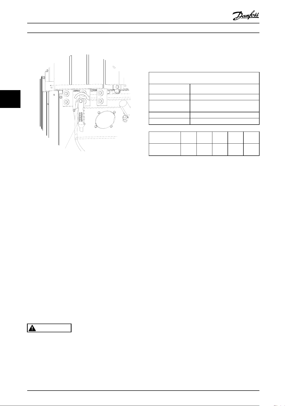
Current transformer specification
The Active Filter supports most current transformers. The
current transformers have to have the following specifications:
Technical specification of Active filter passive current
transformers:
RMS maximum measured RMS current
44
Illustration 4.28 Tightening Bolts with Torque Wrench
Accuracy 0.5% or better (Class 0.5)
Secondary rated
current
Rated frequency 50/60 Hz
Rated power/burden
Rated power/
burden [VA]
Impedance of
current CT [Ω]
Table 4.4 Rated Power/Burden
1A or 5A (5A is recommended)
Set-up via hardware
See Table 4.4 (AAF’s burden equal 2mΩ)
5 7.5 10 15 30
≤ 0.15 ≤ 0.25 ≤ 0.35 ≤ 0.55 ≤ 1.15
NOTE
NOTE
Always use a torque wrench to tighten the bolts.
4.5.6 Shielded Cables
It is important that shielded cables are connected in a
proper way to ensure high EMC immunity and low
emissions.
Connection can be made using either cable glands or
clamps:
EMC cable glands: Generally available cable
•
glands can be used to ensure an optimum EMC
connection.
EMC cable clamp: Clamps allowing easy
•
connection are supplied with the unit.
Current Transformer (CT)
4.5.7
The filter operates in close loop operation by receiving
current signals for external current transformers. The
received signal is processed and the filter reacts according
to programmed actions.
CAUTION
Incorrect current transformer connection, installation or
configuration will lead to unintended and uncontrollable
behaviour of the filter.
All other technical data like dynamic rated current,
maximal permitted operating voltage, thermal
dimensioning of continuous current, thermal dimensioning
of short-time current, over current limit, isolation class,
working temperature range etc. are specific values of the
system and have to be defined during the project planning
phase of the equipment.
RMS Specification
The minimum RMS has to be determined by the total
current that passes through the current transformer. It is
important that the current sensor is not too small leading
to saturation of the sensor. Add 10% margin and pick the
next following bigger standard RMS rate. It is advised to
use current transformers which has a RMS rating close to
the maximum current that flows through it to allow the
highest possible accuracy of the measurement and so an
ideal compensation.
CT Burden
In order to ensure that the current transformer performs
according to specifications, the rated burden should not
be above the true current requirement by the Active Filter.
The burden of the CT is depending on the wire type and
the cable length between the CT and the filter CT
connection terminal. The filter itself contributes with 2mΩ.
NOTE
The accuracy of the CT is depending on wire type and
length of the cable between filter and current transformer.
NOTE
The current transformers are not part of the filter package
and must be purchased separately.
28 MG.90.V2.02 - VLT® is a registered Danfoss trademark
The required (minimum) CT burden can be calculated as:
[VA] = 25*[Ohm/M] *[M]+1.25
[Ohm/M] being the cable resistance in Ohm/meter, [M]
being the cable length in meters
L1
L2
L3
K L
K L
K L
K L
K L
K L
1
2
91 92 93
L1 L2 L3
95
130BB510.11
130BB950.10
1
3
4
5
6
2
How to Install VLT Active Filter AAF 00x
Table 4.5 shows the minimum CT burden for different wire
gauge at wire length of 50m and standard wire resistance
value:
Wire Gauge
[mm2 / AWG]
1.5 / #16 13.3 50 / 164 >16.6
2.5 / #14 8.2 50 / 164 >10.2
4 / #12 5.1 50 / 164 > 6.3
6 / #10 3.4 50 / 164 > 4.2
10 / #8 2 50 / 164 > 2.5
Table 4.5 Minimum CT Burden
Resistance
[Ohm/Km]
Wire length
[meters / feet]
Minimum CT
burden [VA]
For a fixed CT burden the maximum allowed wire length
can be calculated as:
[M] = ([VA]-1.25) / (25*[Ohm/M])
Below the maximum wire length of CT with 2.5mm2 wires
and resistor value equal 8.2 Ohm/km:
Wire Gauge
[mm2 / AWG]
2.5 / #14 8.2 5 <18m / 60
2.5 / #14 8.2 7.5 <30m / 100
2.5 / #14 8.2 10 <42m / 140
2.5 / #14 8.2 15 <67m / 220
2.5 / #14 8.2 30 <140m / 460
Resistance
[Ohm/Km]
Minimum CT
burden [VA]
Wire length
[meter / feet]
4 4
1 or 5 Amp CT Set-up
To allow for possible reuse of already present CT
transformers, the VLT Active Filter allows use of either 1
Amp or 5 Amp CTs. The filter is as standard set-up for 5
Amp CT feedback. If the CTs are 1 Amp, redirect the CT
terminal plug from slot MK101, pos. 1, to MK108, pos. 2,
on the AFC card, see Illustration 4.29.
Example
Calculation example for correct current transformer for an
application with:
RMS= 653Amp, Distance between filter and CT’s of 30m.
RMS=653*1.1= 719A, CT RMS = 750Amp. Burden :
30m@2.5mm2 wire => 25*0.0082*30+1.25=7.4 => 7.5 [VA].
Current transformer installation
The unit only supports three CT installations. External CTs
should be installed on all three phases to detect the
harmonic content of the grid. The flow direction of the
sensor is in most cases indicated by an arrow. The arrow
should point in the direction of the current flow and so
towards the load. In case the flow direction is incorrectly
programmed the polarity can be changed via filter
Illustration 4.29 AFC Board
300-25 CT Polarity. 300-25 CT Polarity can program the
polarity of all three phases individually.
Individual or group compensation
The compensation of the filter depends on the signal that
is returned from the current transformers. The point of
installation for these sensors is so determine the loads that
are corrected.
MG.90.V2.02 - VLT® is a registered Danfoss trademark 29

M M
M
PCC1
PCC2
130BB511.11
AAF
M
M
M
PCC1
PCC2
130BB512.10
AAF
PCC1
AAF
M
M
M
130BB513.11
How to Install VLT Active Filter AAF 00x
If the CTs are installed on the secondary side of the
transformer and so in front of the entire load, the filter will
compensate all loads simultaneously. If as in
Illustration 4.31, the CTs are installed in front of only some
of the loads, the filter will not compensate unwanted
current deformation of the frequency converter and motor
on the right hand side. If CTs are installed in-front of a
single load the filter will only compensate the one load
and so form individual load compensation.
44
The filter can be programmed to have CTs installed on
source side also called point of common coupling (PCC) or
alternatively at the load side. This has to be programmed
via 300-26 CT Placement
NOTE
The filter will as standard be programmed to PCC side
installation
Illustration 4.30 Current transformers installed in front of entire
installation and filter is compensating all loads on the
transformer. CT on PCC side.
Illustration 4.32 Current transformers installed on source (PCC)
side for group compensation.
Illustration 4.31 Current transformers are installed in front of
distribution bus 2 and one frequency converter and the filter
only compensating currents for those. CT on load side.
30 MG.90.V2.02 - VLT® is a registered Danfoss trademark

PCC1
AAF
M
M M
130BB514.11
How to Install VLT Active Filter AAF 00x
- Only one CT per phase (not possible for
summation CTs)
- CTs are part of below standard range:
600 750
1000 1250 1500 2000 2500 3000 3500 4000
Table 4.6 Primary Rating [A]
Illustration 4.33 Current transformers installed on load side for
group compensation.
If the current transformers are installed on the source
(PCC) side the filter will expect a sinusoidal (corrected)
signal feedback form the three sensors. In case the sensors
are installed on the load side the received signal will be
subtracted from the ideal sine wave to calculate the
needed corrected current.
Most restrictions on the current transformers comes from
the installation, such as needed cable length, temperature
conditions, square section of conducts, standard or split
core layout, etc. A broad range of different current
transformers can be used independently of brand and
type.
For specific CT requirements contact the local supplier or
go to
http://www.deif.com/Download_Centre/Search.aspx?searchstring=dct:
Secondary Primary Accuracy Burden Type Description
5 or 1A 30 -
7500A
5 or 1A 100 -
5000A
5 or 1A 5 or 1A 0.5 - 1 15 - 30VAKSU/
Table 4.7 Standard CT Range from Deif - Fits Most Applications
0.2 - 0.5-1 1.0 - 45VAASR
ASK
EASR
EASK
0.5 - 1 1.25 -
30V A
KBU Split core
SUSK
Measuring
current
transformer
for cables
and bus bars
current
transformer
Summation
current
transformer
4 4
NOTE
Erratic filter operation can be a result of incorrect current
transformers connection point programming 300-26 CT
Placement
4.5.8 Auto CT Detection
The VLT Active Filter is able to perform an auto detection
of the installed CT. The CT auto detection can be
conducted both while the system is running and at no
load conditions. The filter injects a prefixed current of
known amplitude and phase angle and is measuring the
returned CT input. The performance is conducted on each
phase individually and for several frequencies to reassure
phase sequence and RMS is set correctly.
The Auto CT detection is pending on the follow conditions:
- Active Filter bigger than 10% of CT RMS rate
- CTs installed on source (PCC) side (auto CT not
possible for load side CT installation)
Summation Transformers
4.5.9
Multiple current sources:
In case the filter is to compensate current from several
sources it is needed to install summation CTs. This is often
the case if filter is installed in systems with generator backup or where the filter is only to compensate a limited
number of loads.
MG.90.V2.02 - VLT® is a registered Danfoss trademark 31

M M
M
PCC1
130BB515.11
AAF
G
M
M
M
AAF
PCC1
130BB516.11
How to Install VLT Active Filter AAF 00x
several sources make sure that all CTs connected to the
summation are from the same manufacturer and that the
CT have:
- same polarity
- same primary rate
- same RMS value
- same accuracy (class 0.5)
44
- same location (PCC or load-side)
- same phase sequence
NOTE
Use summation CT with great caution and always insure
correct phase sequence, current direction, primary and
secondary rate. If installation is incorrect the filter will not
work according to expectations.
The current transformers burden calculation has to include
all wires in the installation and must be conducted for the
Illustration 4.34 Summation CTs on generator backup
applications (PCC-side). Filter compensates full current of
transformer and generator.
longest total wire string when using summation CTs.
4.5.10
Active Filter Operating with
Capacitor Banks
Illustration 4.35 Summation CTs example for individual harmonic
compensation (load side).
The VLT Active Filter is able to run in conjunction with
capacitor banks as long as the resonance frequency of the
capacitor bank is not in the operation range of the Active
Filter.
NOTE
Always use detuned capacitor banks in installation with
frequency converter and active filters to avoid resonance
phenomena, unintended tripping or even component
brake down.
For the case of detuned capacitors, the resonance
frequency capacitors should be tuned for an interharmonic number lower than the 3rd harmonic. The VLT
Active Filter has to operate in selective compensation
mode if filter is installed in conjunction with capacitor
banks of any kind.
Capacitor bank should ideally be installed upstream of the
filter / towards the transformer. If not possible the current
transformers should be installed in a way that they do not
measure both needed current compensation and the
capacitor corrected current.
Summation current transformers are available with
multiple (2-5) inputs and common output. For application
where summations CTs are used to add current from
32 MG.90.V2.02 - VLT® is a registered Danfoss trademark

PCC1
M
M
AAF
130BB517.11
PCC1
130BB518.11
M
M
AAF
PCC1
130BB519.11
M
M
AAF
How to Install VLT Active Filter AAF 00x
4 4
Illustration 4.36 Capacitor bank mounted up stream and CTs
installation does not measure capacitor current.
Illustration 4.36 shows recommended installation of the
active filter and CT placement in installations holding
capacitor banks.
Illustration 4.38 CT’s installation does not measure capacitor
current.
For installations where the CT's connection point can be
moved, Illustration 4.38 is also possible. In some retrofit
applications summation CT is needed to reassure that the
capacitor current is not measured.
Summation CT can also be used to subtract two signals
from each other and so subtract the capacitor bank
corrected current from the total current
Illustration 4.37 Not allowed installation. Corrected capacitor
current interacts with CT measurement.
MG.90.V2.02 - VLT® is a registered Danfoss trademark 33

PCC1
130BB520.11
M
M
AAF
How to Install VLT Active Filter AAF 00x
Fan Fuses
Size/Type Bussmann PN* LittelFuse Rating
A190-250A,
AAF005
A190 - A400,
AAF006
KTK-4 4 A, 600 V
KLK-15 15 A, 600 V
Soft Charge resistor fuses
44
Frame size Bussmann P/N Rating
D and E FNQ-R 1 A, 600 V
Control Transformer fuse
Frame size Bussmann P/N Rating
D and E FNQ-R 3 A, 600 V
4.5.12 Mains Disconnectors
Frame
size Power & Voltage Type
Illustration 4.39 Capacitor bank mounted on PCC, but CTs
installed to reassure that capacitor corrected current is not
measured.
D A190 380-480V ABB OETL-NF200A
E A250 380-480V ABB OETL-NF400A
E A310 380-480V ABB OETL-NF400A
E A400 380-480V ABB OETL-NF800A
4.5.11
Fuses
Branch circuit protection:
In order to protect the installation against electrical and
fire hazard, all branch circuits in an installation, switch
gear, machines etc., must be short-circuited and overcurrent protected according to national/international
regulations.
Short-circuit protection:
The Active Filter must be protected against short-circuit to
avoid electrical or fire hazard. Danfoss recommends using
the fuses mentioned below to protect service personnel
and equipment in case of an internal failure in the device.
Over-current protection
The Active Filter is equipped with an internal over-current
protection that avoids overload in normal running
conditions. Overload protection is however needed in case
of internal failures to avoid fire hazard due to overheating
of the cables in the installation. Fuses or circuit breakers
can be used to provide the needed protection for the
installation. Over-current protection must always be carried
out according to national regulations.
Supplementary fuses
4.5.13 Control and CT Cable Routing
Tie down all control wires to the designated control cable
routing as shown in the picture. Remember to connect the
shields in a proper way to ensure optimum electrical
immunity.
CT connection
Connections are made to the terminal block below the
active filter card. The cable must be placed in the provided
path inside the filter and tied down with other control
wires (see Illustration 4.40 ).
SMPS Fuse
Frame size
D and E KTK-4 4 A, 600 V
34 MG.90.V2.02 - VLT® is a registered Danfoss trademark
Bussmann PN* LittelFuse Rating

130BB742.10
130BA150.10
9 - 10 mm
(0.37 in)
130BT312.10
130BT311.10
How to Install VLT Active Filter AAF 00x
4.5.14
Control Wire Installation
All terminals to the control cables are located on the AFC
board.
To connect the cable to the terminal:
1. Strip insulation by about 9-10mm
2.
Insert a screwdriver1) in the square hole.
4 4
Illustration 4.40 Example of Control Card Wiring Path, D13.
3. Insert the cable in the adjacent circular hole.
4. Remove the screwdriver. The cable is now
mounted in the terminal.
To remove the cable from the terminal:
1.
Insert a screw driver1) in the square hole.
2. Pull out the cable.
1) Max. 0.4 x 2.5mm
MG.90.V2.02 - VLT® is a registered Danfoss trademark 35

Remove jumper to activate Safe Stop
Max. 24
V
olt !
12
13
12
19
27
29
32
33
20
39
42
50
53
54
61
68
130BB744.10
How to Install VLT Active Filter AAF 00x
AC line (jumpers between 100-102 and 101-103). If external
supply is needed, the jumpers are removed and the supply
is connected to terminals 100 and 101. A 5 Amp fuse
should be used for protection. In UL applications this
should be LittleFuse KLK-5 or equivalent.
44
4.5.15 Unscreened Control Wires
CAUTION
Induced Voltage!
Run input power and control wiring in separate metallic
conduits or raceways for high frequency noise isolation.
Failure to isolate power and control wiring could result in
less than optimum controller and associated equipment
performance.
Control wiring including CT-wires should always be
isolated from the high voltage power wiring. When
screened/armoured cable is not used, ensure that control
wires are twisted pairs and keep the maximum possible
distance between mains wire and control cables.
4.5.16
External Fan Supply
In case the Active Filter is supplied by DC or if the fan
must run independently of the power supply, an external
power supply can be applied.
Terminal No.
100, 101
102, 103
The connector located on the power card provides the
connection of line voltage for the cooling fans. The fans
Function
Auxiliary supply S, T
Internal supply S, T
are connected from factory to be supplied form a common
36 MG.90.V2.02 - VLT® is a registered Danfoss trademark

K
K
KL L
L1
L
L2 L3
MK108 (1A) MK101 (5A)
24V (NPN)
24V (NPN)
24V (NPN)
24V (NPN)
24V (NPN)
24V (NPN)
24V (NPN)
0V (PNP)
0V (PNP)
0V (PNP)
0V (PNP)
0V (PNP)
0V (PNP)
0V (PNP)
+24V
+24V
-0V
-0V
0V
5V
MK103
69
61
68
RS-485
Interface
91/L1
92/L2
93/L3
95
Fuse
Option
Manual
disconnect
Switch mode
Power supply
10V DC
15mA
24V DC
200mA
MK102
12
13
18
19
27
29
32
33
20
37
130BB507.11
How to Install VLT Active Filter AAF 00x
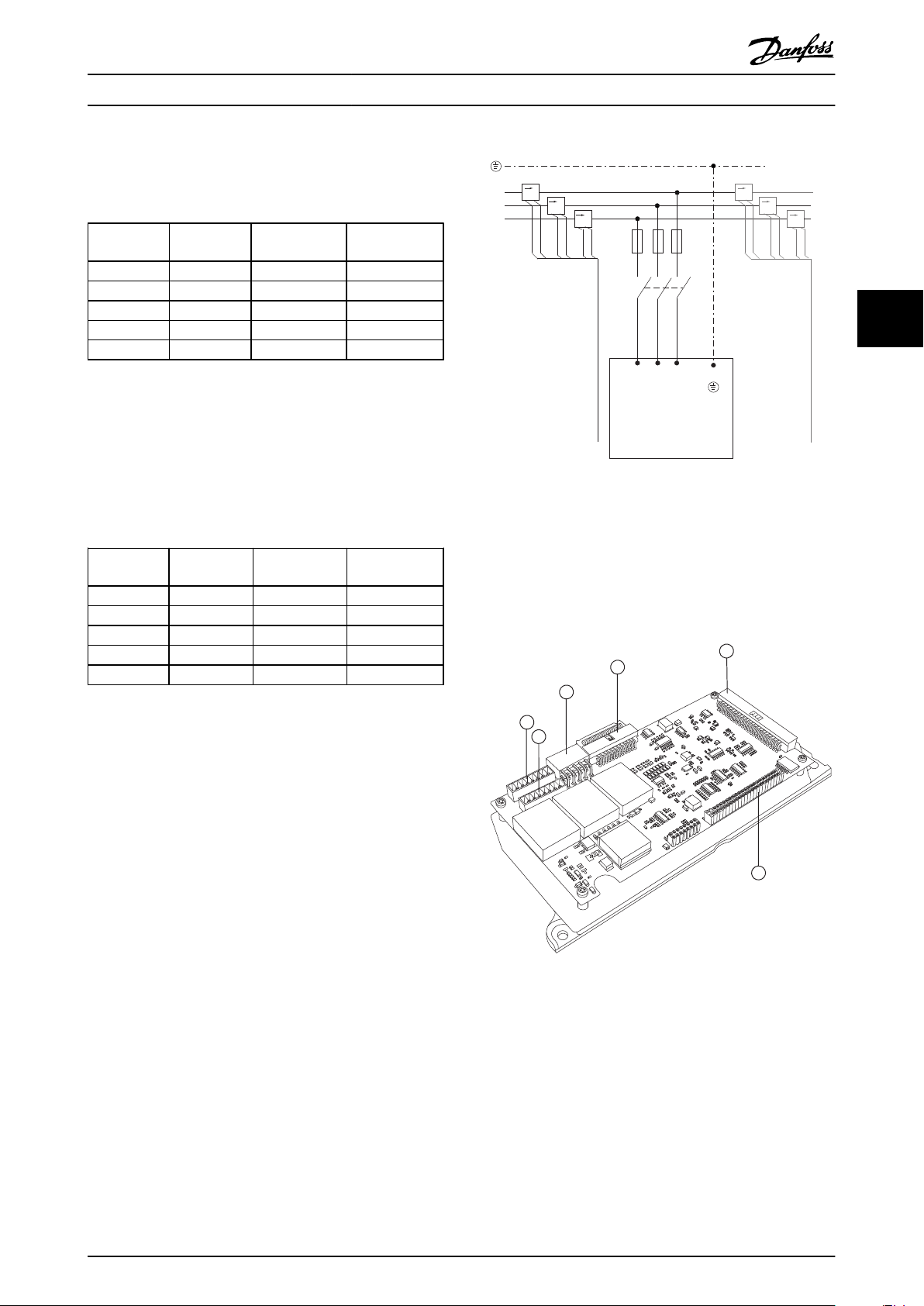
4.6.1 Electrical Installation, Control Cables
4 4
Illustration 4.41 Diagram showing all electrical terminals without options.
Terminals L1, L2 and L3 (91,92,93 and 95) are grid connection terminals Terminal 37 is the input to be used for Safe Stop. Grey scaled
terminals are already used for internal operation or are not configurable via software of the Active Filter.
MK108
1A CT-connection pin MK102 I/O connections
MK101 5A CT-connection pin 91-93 Mains input
MK103 Software communication RS-485
MG.90.V2.02 - VLT® is a registered Danfoss trademark 37

12 13 18 19 27 29 32 33 20 37
+24 VDC
0 VDC
130BT106.10
PNP (Source)
Digital input wiring
NPN (Sink)
Digital input wiring
12 13 18 19 27 29 32 33 20 37
+24 VDC
0 VDC
130BT107.11
130BB745.10
61
68
39
42
50
53
54
Remove jumper to activate Safe Stop
Max. 24 Volt !
12
13
12
19
27
29
32
33
20
How to Install VLT Active Filter AAF 00x
NOTE
Terminals are not all located on the same PCB.
Very long control cables and analogue signals may in rare
cases and depending on installation result in 50/60 Hz
earth loops due to noise from mains supply cables.
If this occurs, it may be necessary to break the screen or
44
insert a 100 nF capacitor between screen and chassis.
Input polarity of control terminals
NOTE
To comply with EMC emission specifications, screened
cables are recommended. If an unscreened cable is used,
see 4.5.15 Unscreened Control Wires. If unscreened control
cables are used, it is recommended to use ferrite cores to
improve EMC performance.
Remember to connect the shields in a proper way to
ensure optimum electrical immunity.
38 MG.90.V2.02 - VLT® is a registered Danfoss trademark

PCC1
130BB713.10
AAF
AAF
AAF
AAF
PCC1
130BB714.10
AAF
AAF
AAF AAF
130BB715.10
F2
F1
L1
12
12
12
M
How to Install VLT Active Filter AAF 00x
4.7 Paralleling of Active Filter Units
The VLT Active Filter is designed to be installed in
networks with other active in-feed current suppliers and so
operate in conjunction with other active filters, UPS’s and
AFE drives. There are no limitations to the maximum
allowed units to be installed. Four filters are allowed to be
connected to the same CT-input and run in a Masterfollower configuration. The Master unit is activating the
individual followers according to mitigation demand in a
cascade network. This keeps the switching losses as low as
possible and so improves the system efficiency. The master
unit will automatically allocate a new follower in case a
unit is out due to service or has unintentionally tripped.
CT-wiring for Parallel Filter
4.7.1
Connection
VLT Active Filter is designed to allow up to 4 units to run
in parallel allowing for a harmonic and reactive compensation extension to four times the individual filter rating.
The parallel installed filters uses the same current input
and so only one external set of CTs have to be installed. In
case additional filtration is needed additional filters have to
use separate current transformers installed up or down
stream to the CT signal and injection point of the
paralleled installation.
The parallel connected filters must have the CT input
signal wired in serial according to Illustration 4.44:
4 4
Illustration 4.43 Four AAFs in Master-Follower
Illustration 4.44 Single phase CT-connection diagram for master
and follower.
CAUTION
All CT wires must be shielded for correct EMC installation.
Unshielded cables can lead to noise on the CT wire and
Illustration 4.42 Two sets of AAFs in Master-Follower.
MG.90.V2.02 - VLT® is a registered Danfoss trademark 39
result in incorrect harmonic filtration.
The current transformers VA-limitation still have to be kept
for filters in parallel and so total wires length has to be
limited according to wire type and CT VA-rating.
[M] = ([VA]-1,25) / (25*[Ohm/M])
See 4.5.1 Power Connections for more details.

M
42
53
27
19
29
20
42
53
27
19
29
20
F1
42
53
27
19
29
20
F2
42
53
27
19
29
20
F3
130BB716.11
How to Install VLT Active Filter AAF 00x
4.7.2 Control Wire Connection for Parallel
Filter Run
Additional to the CT wiring all follower units have to be
connected to the master via either digital or analog inputs.
Below picture shows the necessary control wire
connections:
follower units manually. It is advised to use the following
procedure for setting the CT values:
1.
Program master unit 300-10 Active Filter Nominal
Voltage
2.
Program master unit 300-26 CT Placement
3. Perform an automatic CT detection on master
unit 300-29 Start Auto CT Detection
44
4. Note the auto CT-result and manually program
each follower unit.
5.
Ensure identical settings in 300-10 Active Filter
Nominal Voltage, 300-26 CT Placement and on
each unit.
Illustration 4.45 Control wire connection of follower units F1-F3
(AAF2-4) to master unit M (AAF1)
Alternatively each follower unit can conduct an automatic
CT detection after the master unit is turned off. Only run
one auto CT detection at a time.
Additional to above mentioned CT-setting it is also
The table below shows the necessary connections when
less than four units are paralleled. The software setup of
digital and analog in/output will be done automatically
according to below table based on software programming
300-40 Master Follower Selection and 300-41 Follower ID.
Follower 1 (F1) 27 27
Follower 2 (F2) 27 19
Follower 3 (F3) 42 53
All (parallel) 29 29
All (parallel) 20 20
Terminal connection
at follower
Terminal connection
at master
necessary to set each unit to have its respective role in the
cascade network. 300-40 Master Follower Selection is set to
master or follower for each unit.
300-40 Master Follower Selection
Option: Function:
[0] Master If operating active filters in parallel, select
whether this AF is a master or a follower
active filter.
[1] Follower
[2] * Not Paralleled
WARNING
Make sure only one master is set in each group of parallel
connected filters. Verify that no other unit is set to master.
WARNING
Follower units will not work if control wires are not
correctly connected.
NOTE
It is advised to use shielded control wires for correct EMC
installation.
4.7.3 Software Set-up of Parallel Filter Run
After changing this parameter, additional parameters are
accessible. For the master units 300-42 Num. of Follower AFs
has to be programmed for the amounts of followers
(followers) connected.
300-41 Follower ID
Range: Function:
1* [1 - 3 ] Enter the unique ID of this follower. Verify that no
other follower uses the same ID.
It is not practical to have followers running in different
mitigation mode or with changed priorities individually as
desired performance can not be guarantied. Parallel
NOTE
300-41 Follower ID is not accessible unless 300-40 Master
Follower Selection is set to follower.
connected filters are thus always to be programmed with
same compensation and priority mode. Also make sure all
CT-settings have been set identically in all parallel
connection units, and all has same hardware secondary CT
configuration.
WARNING
Each follower should have it own follower ID. Verify that
no other follower have the same follower ID.
The automatic CT-detection is still effective for filters in
master-follower configuration but it is recommend setting
40 MG.90.V2.02 - VLT® is a registered Danfoss trademark

How to Install VLT Active Filter AAF 00x
300-42 Num. of Follower AFs
Range: Function:
1* [1 - 3 ] Enter the total number of follower active filters. The
master active filter will only control this number of
followers.
NOTE
300-42 Num. of Follower AFs is not accessible unless
300-40 Master Follower Selection is set to master.
Each follower unit has to be programmed at
300-41 Follower ID. The ID of the followers needs to be
different from each other.
Before starting the units (pushing auto-on button) it is
advised to check that the following parameters all have
been correctly programmed and have similar values for all
units sharing one set of CTs:
300-00 Harmonic Cancellation Mode
300-20 CT Primary Rating
300-22 CT Nominal Voltage
300-24 CT Sequence
300-25 CT Polarity
300-26 CT Placement
300-30 Compensation Points
300-35 Cosphi Reference
4.8
Final Set-Up and Test
External CT settings are programmed via parameter group
300-2*. It is advised to perform an automatic CT-detection
for all standalone filters via 300-29 Start Auto CT Detection.
Filter supports all standard CTs with 1A or 5A secondary
rating.
NOTE
The automatic CT-detection is only possible with CT
installed on the source side
CTs should have an accuracy of 0.5% or better to reassure
sufficient accuracy.
CAUTION
Incorrect current transformer connection, installation or
configuration will lead to unintended and uncontrollable
behaviour of the filter.
1.
2.
Follow these steps to reassure correct installed current
transformers:
Performing an Auto CT:
The automatic current transformer detection will set the CT
polarity, phase sequence and current ratio.
Stop the CT detection during operation:
Press the [off] key – the filter enters into alarm mode and
display show that the Auto CT was terminated by the user.
Successful CT detection:
The display will show the found ratios, parameters, and the
phase sequence. Press [OK] to accept the found
parameters. After the CT detection the filter is ready to
start operation.
CT detection failed:
Danfoss CT auto detection support most standard CTs. The
auto CT detection will not succeed if:
A manual configuration is needed in case the automatic CT
detection fails to set the CTs. In that case set the following
parameters according to the CT plate data and installation:
300-26 CT Placement
300-29 Start Auto CT Detection
1. Locate the CT.
2. Note the position in the installation and the
secondary and primary current level.
3. Check that mechanical CT-pin connection MK108
or MK101 is according to CT-secondary rating.
4.
Enter the CT-location in 300-26 CT Placement.
5. Enter the primary current from the plate data in
this 300-20 CT Primary Rating.
CTs are not wired correctly
•
CTs are installed on load side
•
Primary rate is not a standard size
•
Secondary rate and CT placement is not
•
configured
CT current primary rate is bigger then 10 times
•
filter current rate
4 4
To test the set-up and ensure that the Active Filter is
running correctly, follow these steps:
MG.90.V2.02 - VLT® is a registered Danfoss trademark 41
1. 300-20 CT Primary Rating
2. 300-24 phase sequence
3. 300-25 CT polarity

How to Install VLT Active Filter AAF 00x
The active filter allows different CT polarity of all three
current transformers. That means that 300-25 CT Polarity
need to be set for all three CTs individually.
Then the current transducers are successful configured the
filter is ready to start it operation. To setup the filter
compensation mode and priority please consult the
chapter How to programme.
44
42 MG.90.V2.02 - VLT® is a registered Danfoss trademark

Visual inspection:
- Power cables
- Earthing
- CT wiring and 1 or 5A HW check with AF-Card set-up
- Control wire
- Mounting
- Cooling
- Dust
- Temperature
- Glant plate check
Document
Environment
OK Yes
Fluke 435
available
Make grid analyses:
- Connect voltage and current probes at
transformer
- Record THDv and THDi at normal operation and
full load
CT installed at dierent
voltage (MV) then lter
300-22
No
Yes
CT placement
Location: 300-26
PCC side
OK
Check all CTs have
same primary rate
Power-on lter
program I/Os
Document
THDv
Yes
Sum transformers
used
No
Load side
Manual CT set-up:
- Polarity: 300-25
- Sequency: 33-24
- Primary rate: 300-20
Failed
Auto CT
300-29
Remove CT shorts
at the CT terminal
block
Succesful
Program lter mode:
- Priority 300-01
- Cos setpoint 300-35
- Harmonic mode 300-00
- In Selective 300-30
Document
Settings
Fault!
Check
installation
Turn on lter
”Auto mode”
No
Running at around 10-30A
Yes
Stop lter and remove
the three CT-shorts at
CT terminals
Turn on lter
”Auto mode”
Document
Performance
Make grid analyses:
- Record THDv and THDi improvements
- RMS
- True PF and displacement PF
Yes
Fluke 435
available
No
Check CT
settings again
No
Check that THDi read out
value is reduced to 5-9%
when lter is turned on
130BB949.10
How to Install VLT Active Filter AAF 00x
4 4
MG.90.V2.02 - VLT® is a registered Danfoss trademark 43

On
Warm
Alarm
OK
Status
Quick
Menus
Main
Menu
Alarm
Log
Status
1(1)
0.0% 0.0% 0˚C
111A
0A
Auro Running
a
b
c
130BB468.10
Auto
on
Hand
on
O Reset
How to Operate the Active F... VLT Active Filter AAF 00x
5 How to Operate the Active Filter
5.1 Ways of Operation
The Active Filter can be operated in 2 ways:
1. Graphical Local Control Panel (GLCP)
2. RS-485 serial communication or USB, both for PC
connection
55
5.1.1 How to Operate Graphical LCP (GLCP)
The GLCP is divided into four functional groups:
1. Graphical display with Status lines.
2. Menu keys and indicator lights (LED's) - selecting
mode, changing parameters and switching
between display functions.
3. Navigation keys and indicator lights (LEDs).
4. Operation keys and indicator lights (LEDs).
Graphical display:
The LCD-display is back-lit with a total of 6 alpha-numeric
lines. All data is displayed on the LCP which can show up
to five operating variables while in [Status] mode.
Display lines:
a. Status line: Status messages displaying icons and
graphics.
b. Line 1-2: Operator data lines displaying data and
variables defined or chosen by the user. By
pressing the [Status] key, up to one extra line can
be added.
c. Status line: Status messages displaying text.
The display is divided into 3 sections:
The number of the Active Set-up (selected as the Active
Set-up in 0-10 Active Set-up) is shown. When programming
in another Set-up than the Active Set-up, the number of
the Set-up being programmed appears to the right in
brackets.
Top section (a)
shows the status when in status mode or up to 2 variables
when not in status mode and in the case of Alarm/
Warning.
Middle section (b)
shows up to 5 variables with related unit, regardless of
status. In case of alarm/warning, the warning is shown
instead of the variables.
It is possible to toggle between three status read-out
displays by pressing the [Status] key.
Operating variables with different formatting are shown in
each status screen - see below.
Several values or measurements can be linked to each of
the displayed operating variables. The values /
measurements to be displayed can be defined via
parameters 0-20 Display Line 1.1 Small to 0-24 Display Line 3
Large, which can be accessed via [QUICK MENU], "Q3
Function Setups", "Q3-1 General Settings", "Q3-11 Display
Settings".
44 MG.90.V2.02 - VLT® is a registered Danfoss trademark

S ta tus
0.0% 0.0% 0°C
3(3)
1.3
3
2
1.2
1.1
0A
0A
O t op
130BB469.10
1.1 Power Factor
1.2 THD of Current [%]
1.3 Mains Current [A]
2 Output Current [A]
3 Mains Frequency
Info:
130BB470.10
Status:
Top section
Middle section
Bottom section
Status
43 RPM
1.4 Hz
Auto Remote Running
! Pwr.card temp (W29)
2.9%
5.44 A 25.3kW
1(1)
130BP074.10
!
On
Warn.
Alarm
130BP044.10
130BP045.10
Status
Quick
Menu
Main
Menu
Alarm
Log
How to Operate the Active F... VLT Active Filter AAF 00x
Each value / measurement readout parameter selected in
0-20 Display Line 1.1 Small to 0-24 Display Line 3 Large has
its own scale and number of digits after a possible decimal
point. Larger numeric values are displayed with few digits
after the decimal point.
Ex.: Current readout 5.25 A; 15.2 A 105 A.
Status display I
This read-out state is standard after start-up or initialization.
Use [INFO] to obtain information about the value/
measurement linked to the displayed operating variables
(1.1, 1.2, 1.3, 2, and 3).
See the operating variables shown in the display in this
illustration. 1.1, 1.2 and 1.3 are shown in small size. 2 and
3 are shown in medium size.
Status display II
See the operating variables (1.1, 1.2, 1.3, and 2) shown in
the display in this illustration.
In this example the small readout are: Power Factor in the
upper left corner (position 1.1). THiD of Current in the
middle top (position 1.2), The mains current is displayed in
the upper right corner (1.3). Large readouts are the Output
current (position 2) and lastly underneath the mains
frequency is the reactive current at position 3.
1.1, 1.2 and 1.3 are shown in small size. 2 is shown in large
size.
Bottom section
always shows the state of the unit in Status mode.
Indicator lights (LEDs):
If certain threshold values are exceeded, the alarm and/or
warning LED lights up. A status and alarm text appear on
the control panel.
The On LED is activated when the unit receives power
from mains voltage, a DC bus terminal, or an external 24 V
supply. At the same time, the back light is on.
Green LED/On: Control section is working.
•
Yellow LED/Warn.: Indicates a warning.
•
Flashing Red LED/Alarm: Indicates an alarm.
•
LCP keys
Menu keys
The menu keys are divided into functions. The keys below
the display and indicator lamps are used for parameter setup, including choice of display indication during normal
operation.
[Status]
Indicates the status of the filter. Use the [Status] key to
toggle single or double readout mode - 5 line readouts, 4
line readouts.
Use [Status] for selecting the mode of display or for
changing back to Display mode from either the Quick
Menu mode, the Main Menu mode or Alarm mode.
[Quick Menu]
Allows quick set-up of the unit. The most common
functions can be programmed here.
The [Quick Menu] consists of:
- Q1: My Personal Menu
- Q2: Quick Setup
- Q5: Changes Made
- Q6: Loggings
The Quick Menu parameters can be accessed immediately
unless a password has been created via 0-60 Main Menu
Password, 0-61 Access to Main Menu w/o Password,
0-65 Quick Menu Password or 0-66 Access to Quick Menu w/o
Password.
It is possible to switch directly between Quick Menu mode
and Main Menu mode.
5 5
Display contrast adjustment
Press [status] and [▲] for darker display
Press [status] and [▼] for brighter display
MG.90.V2.02 - VLT® is a registered Danfoss trademark 45
[Main Menu]
is used for programming all parameters.
The Main Menu parameters can be accessed immediately
unless a password has been created via 0-60 Main Menu
Password, 0-61 Access to Main Menu w/o Password,

B
a
c
k
C
a
n
c
e
l
I
n
f
o
130BT117.10
OK
Back
Info
Warm
Alarm
On
Cancel
130BP046.10
Hand
on
O
Auto
on
Reset
How to Operate the Active F... VLT Active Filter AAF 00x
0-65 Quick Menu Password or 0-66 Access to Quick Menu w/o
Password.
It is possible to switch directly between Main Menu mode
and Quick Menu mode.
Parameter shortcut can be carried out by pressing down
the [Main Menu] key for 3 seconds. The parameter shortcut
allows direct access to any parameter.
[Alarm Log]
displays an Alarm list of the five latest alarms (numbered
A1-A5). To obtain additional details about an alarm, use
the arrow keys to manoeuvre to the alarm number and
press [OK]. Information is displayed about the condition of
55
the unit before it enters the alarm mode.
[Back]
reverts to the previous step or layer in the navigation
Operation keys
for local control are found at the bottom of the control
panel.
structure.
[Cancel]
last change or command will be cancelled as long as the
display has not been changed.
[Info]
displays information about a command, parameter, or
function in any display window. [Info] provides detailed
information when needed.
[Hand on]
enables control of the filter via the LCP. The key can be
Enabled [1] or Disabled [0] via 0-40 [Hand on] Key on LCP
Exit Info mode by pressing either [Info], [Back], or [Cancel].
The following control signals will still be active when
[Hand on] is activated:
[Hand on] - [Off] - [Auto on]
•
Reset
•
Stop command from serial communication
•
NOTE
External stop signals activated by means of control signals
or a serial bus will override a “start” command via the LCP.
[Off]
stops the unit. The key can be Enabled [1] or Disabled [0]
via 0-41 [Off] Key on LCP. If no external stop function is
Navigation keys
The four navigation arrows are used to navigate between
the different choices available in [Quick Menu], [Main
Menu] and [Alarm Log]. Use the keys to move the cursor.
[OK]
is used for choosing a parameter marked by the cursor
and for enabling the change of a parameter.
selected and the [Off] key is inactive the unit can only be
stopped by disconnecting the mains supply.
[Auto on]
enables the unit to be controlled via the control terminals
and/or serial communication. When a start signal is applied
on the control terminals and/or the bus, the unit will start.
The key can be Enabled [1] or Disabled [0] via 0-42 [Auto
on] Key on LCP.
NOTE
An active HAND-OFF-AUTO signal via the digital inputs has
higher priority than the control keys [Hand on] – [Auto on].
46 MG.90.V2.02 - VLT® is a registered Danfoss trademark
[Reset]
is used for resetting the filter after an alarm (trip). The key
can be Enabled [1] or Disabled [0] via 0-43 [Reset] Key on
LCP.

130BP068.10
740RPM
0 -01 Language
[0] English
10.64 A 1 [1]
0-0
*
Basic Settings
300-20 C T P r imar y
0.0%
C T S ettings
1(1) 0.00
300-2*
R a ting
20 0 A
0
130BB471.10
How to Operate the Active F... VLT Active Filter AAF 00x
The parameter shortcut
can be carried out by holding down the [Main Menu] key
for 3 seconds. The parameter shortcut allows direct access
to any parameter.
5.1.2 Changing Data
The procedure for changing data is the same whether you
select a parameter in the Quick menu or the Main menu
mode. Press [OK] to change the selected parameter. The
procedure for changing data depends on whether the
selected parameter represents a numerical data value or a
text value.
Changing a Text Value
5.1.3
If the selected parameter is a text value, change the text
value by means of the up/down navigation keys.
The up key increases the value, and the down key
decreases the value. Place the cursor on the value to be
saved and press [OK].
Illustration 5.1 Display example.
5.1.4 Changing a Group of Numeric Data
Values
If the chosen parameter represents a numeric data value,
change the chosen data value by means of the [◄] and [►]
navigation keys as well as the up/down [▲] [▼] navigation
keys. Use the [◄] and [►] navigation keys to move the
cursor horizontally.
Illustration 5.3 Display example.
5.1.5 Read-out and Programming of
Indexed Parameters
Parameters are indexed when placed in a rolling stack.
15-30 Alarm Log: Error Code to 15-32 Alarm Log: Time
contain a fault log which can be read out. Choose a
parameter, press [OK], and use the up/down navigation
keys to scroll through the value log.
Use 3-10 Preset Reference as another example:
Choose the parameter, press [OK], and use the up/down
navigation keys keys to scroll through the indexed values.
To change the parameter value, select the indexed value
and press [OK]. Change the value by using the up/down
keys. Press [OK] to accept the new setting. Press [Cancel]
to abort. Press [Back] to leave the parameter.
Tips and Tricks
5.1.6
The AAF hold standard parameters to ensure
•
lowest possible need of changes. For the majority
of applications the Quick Menu, Quick Set-up
provides the simplest and quickest access to all
the typical parameters required.
Performing an Auto CT for all standalone filters to
•
set correct current sensor setup. Auto CT setup is
only possible if CTs are installed at Point of
common coupling PCC (towards the transformer).
CT of LHD is preset from factory.
Under [Quick Menu] and [Changes Made], any
•
parameter that has been changed from factory
settings is displayed.
Press and hold the [Main Menu] key for 3
•
seconds to access any parameter
For service purposes, it is recommended to copy
•
all of the parameters to the LCP, see 0-50 LCP
Copy for further information.
5 5
Illustration 5.2 Display example.
Use the up/down navigation keys to change the data
value. The up key enlarges the data value, and the down
key reduces the data value. Place the cursor on the value
to be saved and press [OK].
MG.90.V2.02 - VLT® is a registered Danfoss trademark 47
5.1.7
Quick Transfer of Parameter Settings
between Multiple Active Filters
Once the set-up of a Filter is complete, we recommend
that you store the data in the LCP or on a PC via MCT 10
Set-up Software.

130BA060.11
68 69 68 69 68 69
RS 485
RS 232
USB
+
-
How to Operate the Active F... VLT Active Filter AAF 00x
Data storage in LCP:
1.
Go to 0-50 LCP Copy
2. Press the [OK] key
NOTE
Parameters selected in 0-25 My Personal Menu, will stay
present, with default factory setting.
3. Select “All to LCP”
Manual initialisation
4. Press the [OK] key
All parameter settings are now stored in the LCP indicated
by the progress bar. When 100% is reached, press [OK].
NOTE
When carrying out manual initialisation, serial communication and fault log settings are reset.
You can now connect the LCP to another filter and copy
the parameter settings to this unit as well.
55
Data transfer from LCP to Filter:
1.
Go to 0-50 LCP Copy
2. Press the [OK] key
3. Select “All from LCP”
4. Press the [OK] key
The parameter settings stored in the LCP are now
transferred to the filter indicated by the progress bar.
When 100% is reached, press [OK].
Initialisation to Default Settings
5.1.8
There are two ways to initialise the filter to default:
This parameter initialises all except:
15-00 Operating Hours
15-03 Power Up's
15-04 Over Temp's
15-05 Over Volt's
1. Disconnect from mains and wait until the
display turns off.
2a. Press [Status] - [Main Menu] - [OK] at the
same time while power up for LCP
2b. Press [Menu] while power up for LCP 101,
Numerical Display
3. Release the keys after 5 secs
4. The active filter is now programmed according
to default settings
recommended initialisation and manual initialisation.
Please be aware that they have different impact according
to the below description.
5.1.9 RS-485 Bus Connection
Recommended initialisation (via 14-22 Operation Mode)
1.
Select 14-22 Operation Mode
2. Press [OK]
The filter can be connected to a controller (or master)
together with other loads using the RS-485 standard
interface. Terminal 68 is connected to the P signal (TX+, RX
+), while terminal 69 is connected to the N signal (TX-,RX-).
3. Select “Initialisation” (for NLCP select “2”)
4. Press [OK]
5. Remove power to unit and wait for display to
turn off.
6. Reconnect power and the unit is reset. Note that
first start-up takes a few more seconds
7. Press [Reset]
14-22 Operation Mode
14-50 RFI Filter
8-30 Protocol
8-31 Address
8-32 Baud Rate
8-35 Minimum Response Delay
8-36 Max Response Delay
8-37 Maximum Inter-Char Delay
15-00 Operating Hours to 15-05 Over Volt's
15-20 Historic Log: Event to 15-22 Historic Log: Time
15-30 Alarm Log: Error Code to 15-32 Alarm Log: Time
initialises all except:
Illustration 5.4 Connection example.
In order to avoid potential equalizing currents in the
screen, earth the cable screen via terminal 61, which is
connected to the frame via an RC-link.
Bus termination
The RS-485 bus must be terminated by a resistor network
at both ends. If the unit is the first or the last device in the
RS-485 loop, set the switch S801 on the control card for
48 MG.90.V2.02 - VLT® is a registered Danfoss trademark
ON..

130BB747.10
61
68
39
42
50
53
54
Remove jumper to activate Safe Stop
Max. 24
Volt !
12
13
12
19
27
29
32
33
20
How to Operate the Active F... VLT Active Filter AAF 00x
5.1.10 How to Connect a PC to the Active
Filter
To control or program the Filter from a PC, install the PCbased Configuration Tool MCT 10 Set-up Software. The PC
is connected via a standard (host/device) USB cable to
both devices, or via the RS-485 interface
NOTE
The USB connection is galvanically isolated from the
supply voltage (PELV) and other high-voltage terminals.
The USB connection is connected to protection earth on
the Active Filter. Use only an isolated laptop as PC
connection to the USB connector on the Active Filter.
MCT 10 Set-up Software software where build in literature
can reveal more usefull information.
MCT 10 Set-up Software
MCT 10 Set-up Software has been designed as an easy to
use interactive tool for setting parameters in our Active
Filters. The software can be downloaded from the Danfoss
internet site http://www.Danfoss.com/BusinessAreas/DrivesSolutions/Softwaredownload/DDPC+Software
+Program.htm.
The MCT 10 Set-up Software will be useful for:
Planning a communication network off-line. MCT
•
10 Set-up Software contains a complete active
filter database
Commissioning active filters on line
•
Saving settings for all active filters
•
Replacing an active filter in a network
•
Simple and accurate documentation of active
•
filter settings after commissioning.
Expanding an existing network
•
Future developed active filters will be supported
•
5 5
Illustration 5.5 For control cable connections, see section on
Control Terminals.
5.1.11
PC-based Configuration Tool MCT 10 Set-up Software
The Active Filter is equipped with one serial communi-
PC Software Tools
cation ports. Danfoss provides a PC tool for
communication between PC and filter, PC-based Configuration Tool MCT 10 Set-up Software. Please consult the
MG.90.V2.02 - VLT® is a registered Danfoss trademark 49

How to Operate the Active F... VLT Active Filter AAF 00x
Save filter settings:
1. Connect a PC to the unit via USB com port.
(NOTE: Use a PC, which is isolated from the
mains, in conjunction with the USB port. Failure
to do so may damage equipment.)
2. Open MCT 10 Set-up Software
3. Choose “Read from drive”
4. Choose “Save as”
All parameters are now stored in the PC.
55
Load filter settings:
1. Connect a PC to the unit via USB com port
2. Open MCT 10 Set-up Software
3. Choose “Open”– stored files will be shown
4. Open the appropriate file
5. Choose “Write to drive”
All parameter settings are now transferred to the filter.
A separate manual for MCT 10 Set-up Software is available:
MG.10.Rx.yy.
The MCT 10 Set-up Software modules
The following modules are included in the software
package:
MCT 10 Set-up Software
Setting parameters
Copy to and from unit
Documentation and print out of parameter
settings incl. diagrams
Ext. user interface
Preventive Maintenance Schedule
Clock settings
Timed Action Programming
Smart Logic Controller Set-up
Ordering number:
Please order the CD containing MCT 10 Set-up Software
using code number 130B1000.
MCT 10 Set-up Software can also be downloaded from the
Danfoss Internet: WWW.DANFOSS.COM, Business Area:
Motion Controls.
50 MG.90.V2.02 - VLT® is a registered Danfoss trademark

01 My Personal Menu
02 Quick Setup
05 Changes Made
06 Loggings
0.0% 0.00
Quick Menus
1(1)
130BB473.10
How to Programme VLT Active Filter AAF 00x
6 How to Programme
6.1.1 Parameter Set-up
The factory settings for the Active Filter are chosen for
optimal operation for most applications with a minimum
of programming needed. The filter is set in overall
harmonic compensation mode with harmonic current
priority. Selection of readouts and what information to be
displayed on the LCP status lines can be made to fit
individual preferences. The filter will only in a few cases
have to be tuned specially for the given grid and load
conditions.
The following steps are often sufficient, to set up the filter
and get proper operation:
Program the external CTs:
•
-
Check that the CT-location is correct in
300-26 CT Placement
-
Activate the Auto CT Detection in
300-29 Start Auto CT Detection
- Confirm the found CT-ratio, polarity, and
sequence.
Make sure that the filter is in auto mode (press
•
[Auto On] on the LCP)
Parameter descriptions and selections are displayed on the
graphic (LCP) display area. (See 5 How to Operate the Active
Filter for details.) Access the parameters by pressing the
[Quick Menu] or [Main Menu] key on the control panel.
The quick menu is used primarily for commissioning the
unit at start-up by providing those parameters necessary
to start operation. The main menu provides access to all
parameters for detailed application programming. All
digital input/output terminals are multifunctional. All
terminals have factory default functions suitable for most
applications but if other special functions are required,
they must be programmed in parameter group 5-**.
The optimum way to set parameters through the [Quick
Menu] is by following the below steps:
1. Press [Quick Setup] for selecting language,
compensation mode, CT-setup, etc.
2. Press [My personal Menu] to setup the LCP
readout parameters. If preset display is acceptable
this operation can be left out.
It is recommended to do the set-up in the order listed.
Illustration 6.1 Quick Menu view.
If No Operation is selected in terminal 27 no connection to
+24 V on terminal 27 is necessary to enable start.
If Coast Inverse is selected in Terminal 27, a connection to
+24V is necessary to enable start.
Q1 My Personal Menu
6.1.3
Parameters defined by the user can be stored in Q1 My
Personal Menu. Select My Personal Menu to display only
the parameters, which have been pre-selected and
programmed as personal parameters. A large scale Active
filter user may have pre-programmed important setup
values in the My Personal Menu to make on site commissioning / fine-tuning simpler. These parameters are
selected in 0-25 My Personal Menu. Up to 20 different
parameters can be defined in this menu.
6
6
Quick Menu Mode
6.1.2
The GLCP provides access to all parameters listed under
the Quick Menus. To set parameters using the [Quick
Menu] button:
Pressing [Quick Menu] the list indicates the different areas
contained in the Quick menu.
Efficient parameter set-up for most applications
The parameters can easily be set up for most the
applications only by using the [Quick Menu].
MG.90.V2.02 - VLT® is a registered Danfoss trademark 51
Q1 My Personal Menu
Parameter number and Name Factory default
0-01 Language
0-20 Display Line 1.1 Small
0-21 Display Line 1.2 Small
0-22 Display Line 1.3 Small
0-23 Display Line 2 Large
0-24 Display Line 3 Large
15-51 Frequency Converter Serial
Number
English
Power Factor
THD of current
Mains current
Output current (corrected)
Mains frequency

How to Programme VLT Active Filter AAF 00x
6
6.1.4 Q2 Quick Setup
The parameters in Q2 Quick Setup are the basic
parameters which are always needed to set up the Active
Filter to operation.
Q2 Quick Setup
Parameter number and
Name
0-01 Language
300-22 CT Nominal Voltage
300-29 Start Auto CT
Detection
300-01 Compensation
Priority
300-00 Harmonic Cancellation Mode
Factory default
English
Same as AF
Off
Harmonics
Overall
NOTE
It is necessary to set the nominal voltage and CT
Secondary rating, as well as change 300-26 CT Placement to
PCC, before the Auto CT detection is started. Auto CT
detection is only possible if CTs are located at the point of
common coupling.
6.1.7 Main Menu mode
The LCP provide access to the main menu mode. Select
the Main Menu mode by pressing the [Main Menu] key.
shows the resulting readout, which appears on the display
of the GLCP.
Lines 2 through 5 on the display show a list of parameter
groups which can be chosen by toggling the up and down
buttons.
Each parameter has a name and number which remain the
same regardless of the programming mode. In the Main
Menu mode, the parameters are divided into groups. The
first digit of the parameter number (from the left) indicates
the parameter group number. All parameters can be
changed in the Main Menu. Option cards added to the
unit enable additional parameters associated with the
option device.
6.1.5 Q5 Changes Made
Q5 Changes Made can be used for fault finding.
Select Changes made to get information about:
- • the last ten changes. Use the up/down
navigation keys to scroll between the last ten
changed parameters.
- the changes made since default setting.
Q6 Loggings
6.1.6
Q6 Loggings can be used for fault finding.
Select Loggings to get information about the display line
readouts. The information is shown as graphs. Only display
parameters selected in 0-20 Display Line 1.1 Small and
0-24 Display Line 3 Large can be viewed. It is possible to
store up to 120 samples in the memory for later reference.
Please notice that the parameters listed in the below table
for Q6 only serve as examples as they will vary depending
on the programming of the particular Active Filter.
Q6 Loggings
0-20 Display Line 1.1 Small
0-21 Display Line 1.2 Small
0-22 Display Line 1.3 Small
Power Factor
THD of current
Mains Current
0-23 Display Line 2 Large
0-24 Display Line 3 Large
52 MG.90.V2.02 - VLT® is a registered Danfoss trademark
Output Current
Mains Frequency

How to Programme VLT Active Filter AAF 00x
6.1.8 Parameter Selection
In the Main Menu mode, the parameters are divided into groups. Select a parameter group with the navigation keys.
The following parameter groups are accessible:
Group Title Function
0-** Operation / Display Parameters related to the fundamental functions of the filter, function of the LCP
buttons and configuration of the LCP display.
5-** Digital In/Out Parameter group for configuring the digital inputs and outputs.
8-** Communication and Options Parameter group for configuring communications and options.
14-** Special Functions Parameter group for configuring special filter functions.
15-** Unit Information Parameter group containing filter information such as operating data, hardware
configuration, and software versions.
16-** Data Readouts Parameter group for data readouts, e.g. actual references, voltages, control, alarm,
warning, and status words.
300-** AF Settings Parameter group for setting the Active Filter. Apart from par. 300-10, Active Filter
Nominal Voltage, it is not recommended to change the settings of this parameter
group.
301-** AF Readouts Parameter group for the filter readouts.
Table 6.1 Parameter groups
6
6
After selecting a parameter group, choose a parameter with the navigation keys.
The middle section on the GLCP display shows the parameter number and name as well as the selected parameter value.
MG.90.V2.02 - VLT® is a registered Danfoss trademark 53

How to Programme VLT Active Filter AAF 00x
6
6.2 Description of Parameters
6.2.1 Main Menu
The Main Menu includes all available parameters in the
VLT® Active Filter. All parameters are grouped in a logic
way with a group name indicating the function of the
parameter group. All parameters are listed by name and
number in the following section. A quicker overview can
be found in the Parameter Lists later in this manual.
6.3 0-** Operation/Display
Parameters related to the fundamental functions of the
Active Filter, function of the LCP buttons and configuration
of the LCP display.
0-0* Basic Settings
6.3.1
0-01 Language
Option: Function:
Defines the language to be used in the
display. The filter can be delivered with 4
different language packages. English and
German are included in all packages.
English cannot be erased or
manipulated.
[0] * English Part of Language packages 1 - 4
[1] Deutsch Part of Language packages 1 - 4
[2] Francais Part of Language package 1
[3] Dansk Part of Language package 1
0-01 Language
Option: Function:
Srpski Part of Language package 3
Romanian Part of Language package 3
Magyar Part of Language package 3
Czech Part of Language package 3
Polski Part of Language package 4
Russian Part of Language package 3
Thai Part of Language package 2
Bahasa Indonesia Part of Language package 2
[52] Hrvatski
6.3.2 0-04 Operating State at Power-up
(Hand)
0-04 Operating State at Power-up (Hand)
Option: Function:
Selects the operating mode upon
reconnection of the filter to mains voltage
after power down in Hand (local) operation
mode.
[0] Resume Restarts the filter maintaining the same start/
stop settings (applied by [HAND ON/OFF]) as
before the filter was powered down.
[1] * Forced stop Restarts the filter with a saved local reference,
after mains voltage reappears and after
pressing [HAND ON].
[4] Spanish Part of Language package 1
[5] Italiano Part of Language package 1
Svenska Part of Language package 1
[7] Nederlands Part of Language package 1
[10] Chinese Part of Language package 2
Suomi Part of Language package 1
[22] English US Part of Language package 4
Greek Part of Language package 4
Bras.port Part of Language package 4
Slovenian Part of Language package 3
Korean Part of Language package 2
Japanese Part of Language package 2
Turkish Part of Language package 4
Trad.Chinese Part of Language package 2
Bulgarian Part of Language package 3
6.3.3 0-1* Set-up Operations
Define and control the individual parameter setups.
The filter has four parameter setups that can be
programmed independently of each other. This makes the
filter very flexible.
The active setup (i.e. the setup in which the filter is
currently operating) can be selected in 0-10 Active Set-up
and is displayed in the LCP. Using Multi set-up it is
possible to switch between setups with the filter running
or stopped, via digital input or serial communication
commands. If it is necessary to change setups whilst
running, ensure 0-12 This Set-up Linked to is programmed
as required. Using 0-11 Edit Set-up it is possible to edit
parameters within any of the setups whilst continuing the
filter operation in its Active Setup which can be a different
setup to that being edited. Using 0-51 Set-up Copy it is
possible to copy parameter settings between the setups to
enable quicker commissioning if similar parameter settings
are required in different setups.
54 MG.90.V2.02 - VLT® is a registered Danfoss trademark

130BP075.10
0-12 This Set-up Linked to
0 RPM
0.00A
1(1)
Set-up Handling 0-1*
[1]
Setup 1
130BP076.10
0-12 This Set-up Linked to
0 RPM
0.00A
1(1)
Set-up Handling
0-1*
[2]
Setup 2
How to Programme VLT Active Filter AAF 00x
0-10 Active Set-up
Option: Function:
Select the set-up to control the filter
functions.
[0] Factory setup Cannot be changed. It contains the Danfoss
data set, and can be used as a data source
when returning the other set-ups to a
known state.
[1] * Set-up 1
[2] Set-up 2
[3] Set-up 3
[4] Set-up 4
[9] Multi Set-up Remote selection of set-ups using digital
Set-up 1 [1] to Set-up 4 [4] are the four
separate parameter set-ups within which all
parameters can be programmed.
inputs and the serial communication port.
This set-up uses the settings from 0-12 This
Set-up Linked to. Stop the filter before
making changes to open- and closed loop
functions
Use 0-51 Set-up Copy to copy a set-up to one or all other
set-ups. Stop the filter before switching between set-ups
where parameters marked ‘not changeable during
operation’ have different values. To avoid conflicting
settings of the same parameter within two different setups, link the set-ups together using 0-12 This Set-up Linked
to. Parameters which are ‘not changeable during operation’
are marked FALSE in the parameter lists in the section
Parameter Lists.
0-12 This Set-up Linked to
Option: Function:
containing parameters which are not
changeable during operation. The link will
ensure synchronising of the ‘not changeable
during operation’ parameter values when
moving from one set-up to another during
operation. ‘Not changeable during operation’
parameters can be identified by the label FALSE
in the parameter lists in the section Parameter
Lists.
0-12 This Set-up Linked to is used by Multi set-
up in 0-10 Active Set-up. Multi set-up is used to
move from one set-up to another during
operation (i.e. while the filter is running).
Example:
Use Multi set-up to shift from Set-up 1 to Setup 2 whilst the motor is running. Programme in
Set-up 1 first, then ensure that Set-up 1 and
Set-up 2 are synchronised (or ‘linked’). Synchronisation can be performed in two ways:
1. Change the edit set-up to Set-up 2 [2] in
0-11 Edit Set-up and set 0-12 This Set-up Linked
to to Set-up 1 [1]. This will start the linking
(synchronising) process.
6
6
0-11 Edit Set-up
Option: Function:
[0] Factory setup Cannot be edited but it is useful as a data
[1] * Set-up 1
[2] Set-up 2
[3] Set-up 3
[4] Set-up 4
[9] Active Set-up Can also be edited during operation. Edit
0-12 This Set-up Linked to
Option: Function:
Select the set-up to be edited (i.e.
programmed) during operation; either the
active set-up or one of the inactive set-ups.
source to return the other set-ups to a
known state.
Set-up 1 [1] to Set-up 4 [4] can be edited
freely during operation, independently of
the active set-up.
the chosen set-up from a range of sources:
LCP, FC RS-485, FC USB or up to five fieldbus
sites.
To enable conflict-free changes from one set-up
to another during operation, link set-ups
MG.90.V2.02 - VLT® is a registered Danfoss trademark 55
[0]
* Not linked
[1] Set-up 1
OR
2. While still in Set-up 1, copy Set-up 1 to Setup 2. Then set 0-12 This Set-up Linked to to Set-
up 2 [2]. This will start the linking process.
After the link is complete, 0-13 Readout: Linked
Set-ups will read {1,2} to indicate that all ‘not
changeable during operation’ parameters are
now the same in Set-up 1 and Set-up 2. If there
are changes to a ‘not changeable during
operation’ parameter, e.g. 1-30 Stator Resistance
(Rs), in Set-up 2, they will also be changed
automatically in Set-up 1. A switch between
Set-up 1 and Set-up 2 during operation is now
possible.

6
How to Programme VLT Active Filter AAF 00x
0-12 This Set-up Linked to
6.3.4
Option: Function:
[2] Set-up 2
[3] Set-up 3
[4] Set-up 4
Define the variables displayed in the Graphical Local
Control Panel.
NOTE
0-13 Readout: Linked Set-ups
Array [5]
Range: Function:
0 * [0 - 255 ] View a list of all the set-ups linked by means of
0-12 This Set-up Linked to. The parameter has one
index for each parameter set-up. The parameter
value displayed for each index represents which
setups are linked to that parameter setup.
Index LCP value
0 {0}
1 {1,2}
2 {1,2}
3 {3}
4 {4}
Table 6.3 Example: Set-up 1 and Set-up 2 are
linked
0-14 Readout: Edit Set-ups / Channel
Range: Function:
0* [-2147483648 -
2147483647 ]
View the setting of 0-11 Edit Set-up for each
of the four different communication
channels. When the number is displayed in
hex, as it is in the LCP, each number
represents one channel.
Numbers 1-4 represent a set-up number; ‘F’
means factory setting; and ‘A’ means active
set-up. The channels are, from right to left:
LCP, FC-bus, USB, HPFB1-5.
Example: The number AAAAAA21h means
that the FC bus selected Set-up 2 in
0-11 Edit Set-up, the LCP selected Set-up 1
and all others used the active set-up.
Please refer to 0-37 Display Text 1, 0-38 Display Text 2 and
0-39 Display Text 3 for information on how to write display
texts.
0-2* LCP Display
0-20 Display Line 1.1 Small
Option: Function:
Select a variable for display in
line 1, left position.
[0] None No display value selected.
[1501] Running Hours
[1600] Control Word Present control word
[1603] Status Word Present status word.
[1630] DC Link Voltage Intermediate circuit voltage in
the unit.
[1634] Heatsink Temp. Present heat sink temperature
of the unit. The cut-out limit is
95 ±5 oC; cutting back in
occurs at 70 ±5° C.
[1635] Inverter Thermal Percentage load of the
inverters.
[1636] Inv. Nom. Current Nominal current of the unit.
[1637] Inv. Max. Current Maximum current of the unit.
[1639] Control Card Temp. Temperature of the control
card.
[1660] Digital Input Signal states form the 6 digital
terminals (18, 19, 27, 29, 32
and 33). There are 16 bits in
total, but only six of them are
used. Input 18 corresponds to
the leftmost of the used bits.
Signal low = 0; Signal high =
1.
[1666] Digital Output [bin] Binary value of all digital
outputs.
[1671] Relay Output [bin]
[1680] Fieldbus CTW 1 Control word (CTW) received
from the Bus Master.
[1684] Comm. Option STW Extended fieldbus communi-
cation option status word.
[1685] FC Port CTW 1 Control word (CTW) received
from the Bus Master.
[1690] Alarm Word One or more alarms in a Hex
code.
[1691] Alarm Word 2 One or more alarms in a Hex
code.
[1692] Warning Word One or more warnings in a
Hex code.
[1693] Warning Word 2 One or more warnings in a
Hex code.
56 MG.90.V2.02 - VLT® is a registered Danfoss trademark

How to Programme VLT Active Filter AAF 00x
0-20 Display Line 1.1 Small
Option: Function:
[1694] Ext. Status Word One or more status conditions
in a Hex code.
[3430] PCD 10 Read from MCO
[30100] Digital Inputs
[30101] Digital Outputs
[30102] Commanded Position
[30103] Slave Index Position
[30104] Curve Position
[30107] Synchronizing Error
[30108] Actual Master Velocity
[30109] Axis Status
[30110] MCO 302 Status
[30120] MCO 302 Control
[30121] MCO Alarm Word 1
[30122] MCO Alarm Word 2
[30123] Idle time
[30124] Paramdb requests in
queue
[30130] tCon1 time
[30131] tCon2 time
[30132] Time Optimize Measure
[30133] HS Temp. (PC1)
[30134] HS Temp. (PC2)
[30135] HS Temp. (PC3)
0-21 Display Line 1.2 Small
Option: Function:
[0] * None Select a variable for display in line 1, middle
position. The options are the same as listed for
0-20 Display Line 1.1 Small.
0-22 Display Line 1.3 Small
Option: Function:
[30120] * Mains Current
[A]
Select a variable for display in line 1,
right position. The options are the
same as listed for 0-20 Display Line 1.1
Small.
0-23 Display Line 2 Large
Option: Function:
[30100] * Output Current
[A]
Select a variable for display in line 2.
The options are the same as listed for
0-20 Display Line 1.1 Small.
0-24 Display Line 3 Large
Select a variable for display in line 3.
Option: Function:
[30121] * Mains Frequency The options are the same as those
listed in 0-20 Display Line 1.1 Small.
0-25 My Personal Menu
Range: Function:
Application
dependent*
6.3.5
[0 9999 ]
Define up to 50 parameters to appear in
the Q1 Personal Menu, accessible via
the [Quick Menu] key on the LCP. The
parameters will be displayed in the Q1
Personal Menu in the order they are
programmed into this array parameter.
Delete parameters by setting the value
to ‘0000’.
For example, this can be used to
provide quick, simple access to just one
or up to 50 parameters which require
changing on a regular basis (e.g. for
plant maintenance reasons) or by an
OEM to enable simple commissioning of
their equipment.
0-4* LCP Keypad
Enable, disable and password protect individual keys on
the LCP.
0-40 [Hand on] Key on LCP
6.3.6
0-40 [Hand on] Key on LCP
Option: Function:
[0] Disabled No effect when [Hand on] is pressed. Select [0]
Disabled to avoid accidental start of the
frequency converter in Hand on mode.
[1] * Enabled
[2] Password
Avoids unauthorised stop. If 0-41 [Off] Key on LCP
is included in the Quick Menu, then define the
password in 0-65 Quick Menu Password.
0-41 [Off] Key on LCP
Option: Function:
[0] * Disabled Avoids accidental stop of the unit.
[1] * Enabled
[2] Password
Avoids unauthorised stop. If 0-41 [Off] Key on LCP
is included in the Quick Menu, then define the
password in 0-65 Quick Menu Password.
0-42 [Auto on] Key on LCP
Option: Function:
[0] * Disabled Avoid accidental start of the unit in Auto mode.
[1] * Enabled
[2] Password
Avoids unauthorised start in Auto mode. If
0-42 [Auto on] Key on LCP is included in the
Quick Menu, then define the password in
0-65 Quick Menu Password.
6
6
MG.90.V2.02 - VLT® is a registered Danfoss trademark 57

How to Programme VLT Active Filter AAF 00x
6
0-43 [Reset] Key on LCP
Option: Function:
[0] * Disabled No effect when [Reset] is pressed. Avoids
accidental alarm reset.
[1] * Enabled
[2] Password
[7] Enabled
without OFF
[8] Password
without OFF
Avoids unauthorised resetting. If
0-43 [Reset] Key on LCP is included in the
Quick Menu, then define the password in
0-65 Quick Menu Password.
Resets the frequency converter without
setting it in Off mode.
Resets the frequency converter without
setting it in Off mode. A password is
required when pressing [Reset] (see [2]).
6.3.7 0-5* Copy / Save
Copy parameter settings between set-ups and to/from the
LCP.
0-50 LCP Copy
Option: Function:
[0] * No copy
[1] All to LCP Copies all parameters in all set-ups
from the filter memory to the LCP
memory.
[2] All from LCP Copies all parameters in all set-ups
from the LCP memory to the filter
memory.
[3] Size indep. from
LCP
[4] File from MCO to
LCP
[5] File from LCP to
MCO
[6] Data from DYN to
LCP
[7] Data from LCP to
DYN
This parameter cannot be adjusted while the motor is
running.
Copy only the parameters that are
independent of the motor size. The
latter selection can be used to
programme several filters with the
same function without disturbing
motor data.
0-51 Set-up Copy
Option: Function:
[2] Copy to set-
up 2
[3] Copy to set-
up 3
[4] Copy to set-
up 4
[9] Copy to all Copies the parameters in the present set-up
Copies all parameters in the present
Programming Set-up (defined in
0-11 Programming Set-up) to Set-up 2.
Copies all parameters in the present
Programming Set-up (defined in
0-11 Programming Set-up) to Set-up 3.
Copies all parameters in the present
Programming Set-up (defined in
0-11 Programming Set-up) to Set-up 4.
over to each of the set-ups 1 to 4.
6.3.8 0-6* Password
0-60 Main Menu Password
Range: Function:
100 * [0 - 999 ] Define the password for access to the Main
Menu via the [Main Menu] key. If 0-61 Access
to Main Menu w/o Password is set to Full
access [0], this parameter will be ignored.
0-61 Access to Main Menu w/o Password
Option: Function:
[0] * Full access
[1] LCP: Read only Prevent unauthorized editing of Main Menu
[2] LCP: No access Prevent unauthorized viewing and editing
[3] Bus: Read only Read-only functions for parameters on
[4] Bus: No access No access to parameters is allowed via
[5] All: Read only Read-only function for parameters on LCP,
[6] All: No access No access from LCP, fieldbus or FC
If Full access [0] is selected then 0-60 Main Menu Password,
0-65 Personal Menu Password and 0-66 Access to Personal
Menu w/o Password will be ignored.
Disables password defined in 0-60 Main
Menu Password.
parameters.
of Main Menu parameters.
fieldbus and/or FC standard bus.
fieldbus and/or FC standard bus.
fieldbus or FC standard bus.
standard bus is allowed.
0-51 Set-up Copy
Option: Function:
[0] * No copy No function
[1] Copy to set-
up 1
58 MG.90.V2.02 - VLT® is a registered Danfoss trademark
Copies all parameters in the present
Programming Set-up (defined in
0-11 Programming Set-up) to Set-up 1.

How to Programme VLT Active Filter AAF 00x
NOTE
A more complex Password protection is available for OEMs
upon request.
0-65 Quick Menu Password
Range: Function:
200* [-9999 -
9999 ]
0-66 Access to Quick Menu w/o Password
Option: Function:
[0] * Full access
[1] LCP: Read only Prevents unauthorised editing of Quick
[2] LCP: No access Prevents unauthorised viewing and editing
[3] Bus: Read only Read only functions for Quick Menu
[4] Bus: No access No access to Quick Menu parameters is
[5] All: Read only read only function for Quick Menu
[6] All: No access No access from LCP, fieldbus or FC
If 0-61 Access to Main Menu w/o Password is set to Full
access [0] then this parameter will be ignored.
6.4
5-** Digital I/O Mode
6.4.1 5-0* Digital I/O Mode
Parameters for configuring the input and output using
NPN and PNP.
These parameters cannot be adjusted while motor is
running.
Define the password for access to the Quick
Menu via the [Quick Menu] key. If
0-66 Access to Quick Menu w/o Password is
set to Full access [0], this parameter will be
ignored.
Disables the password defined in
0-65 Quick Menu Password.
Menu parameters.
of Quick Menu parameters.
parameters on fieldbus and/ or FC standard
bus.
allowed via fieldbus and/ or FC standard
bus.
parameters on LCP, fieldbus or FC standard
bus.
standard bus is allowed.
5-00 Digital I/O Mode
Option: Function:
[1] NPN
Action on negative directional pulses (↕). NPN
systems are pulled up to + 24 V, internally in the
filter.
NOTE
Once this parameter has been changed, it must be
activated by performing a power cycle.
This parameter cannot be adjusted while the motor is
running.
5-01 Terminal 27 Mode
Option: Function:
[0] * Input Defines terminal 27 as a digital input.
[1] Output Defines terminal 27 as a digital output.
5-02 Terminal 29 Mode
Option: Function:
[0] * Input Defines terminal 29 as a digital input.
[1] Output Defines terminal 29 as a digital output.
6.4.2 5-1* Digital Inputs
Parameters for configuring the input functions for the
input terminals.
The digital inputs are used for selecting various functions
in the filter. All digital inputs can be set to the following
functions:
Digital input function
No operation [0] All *term 32, 33
Reset [1] All
Stop inverse [6] All
Start [8] All *term 18
Latched start [9] All
Set-up select bit 0 [23] All
Set-up select bit 1 [24] All
Pulse input Time Based [32] 29, 33
Follower AF # 1 Run
Feedback
Follower AF # 2 Run
Feedback
Sleep [101] T18, T19, T27, T29
Select Terminal
[99] All
[100] All
6
6
5-00 Digital I/O Mode
Option: Function:
Digital inputs and programmed digital outputs are
pre-programmable for operation either in PNP or NPN
systems.
[0] * PNP
Action on positive directional pulses (↕). PNP systems
are pulled down to GND.
Functions dedicated to only one digital input are stated in
the associated parameter.
5-10 Terminal 18 Digital Input
Option: Function:
[0] No operation No reaction to signals transmitted to the
terminal.
MG.90.V2.02 - VLT® is a registered Danfoss trademark 59

How to Programme VLT Active Filter AAF 00x
6
5-10 Terminal 18 Digital Input
Option: Function:
[1] Reset Resets filter after a TRIP/ALARM. Not all
alarms can be reset.
[6] Stop inverse Stop Inverted function. Generates a stop
function when the selected terminal goes
from logical level ‘1’ to ‘0’.
[8] * Start (Default Digital input 18): Select start for a
start/stop command. Logic ‘1’ = start, logic
‘0’ = stop.
[9] Latched Start The filter starts, if a pulse is applied for
min. 2 ms. The filter stops when Stop
inverse is activated.
[23] Set-up select
bit 0
[24] Set-up select
bit 1
[32] Master cmd
pulse in
[99] Follower AF
#1 Run
Feedback
[100] Follower AF
#2 Run
Feedback
[101] Sleep The filter goes into sleep mode at light
Select Set-up select bit 0 or Select Set-up
select bit 1 to select one of the four setups. Set 0-10 Active Set-up to Multi Set-up.
(Default Digital input 32): Same as Set-up
select bit 0 [23].
Time based pulse input measures the
duration between flanks. This gives a
higher resolution at lower frequencies, but
is not as precise at higher frequencies. This
principle has a cut-off frequency which
makes it unsuited for encoders with very
low resolutions (e.g. 30 ppr) at low speeds.
Do not program this setting. It is done
automatically for paralleling. See
300-40 Master Follower Selection and
300-41 Follower ID for more infomation
about paralleling.
Do not program this setting. It is done
automatically for paralleling. See
300-40 Master Follower Selection and
300-41 Follower ID for more infomation
about paralleling.
duty to save energy.
5-14 Terminal 32 Digital Input
Option: Function:
[90] * AC Contactor
Functions are described under 5-1* Digital
Inputs
5-15 Terminal 33 Digital Input
Option: Function:
[91] * DC Contactor
Functions are described under 5-1* Digital
Inputs
5-16 Terminal X30/2 Digital Input
Option: Function:
[0] * No operation
Functions are described under 5-1* Digital
Inputs
5-17 Terminal X30/3 Digital Input
Option: Function:
[0] * No operation
Functions are described under 5-1* Digital
Inputs
5-18 Terminal X30/4 Digital Input
Option: Function:
[0] * No operation
Functions are described under 5-1* Digital
Inputs
5-11 Terminal 19 Digital Input
Option: Function:
[0] * No Operation
Functions are described under 5-1* Digital
Inputs
5-12 Terminal 27 Digital Input
Option: Function:
[0] * No Operation
Functions are described under 5-1* Digital
Inputs
5-13 Terminal 29 Digital Input
Option: Function:
[0] * No Operation
60 MG.90.V2.02 - VLT® is a registered Danfoss trademark
Functions are described under 5-1* Digital
Inputs

How to Programme VLT Active Filter AAF 00x
5-19 Terminal 37 Safe Stop
Option: Function:
[1]*Safe Stop
Alarm
[3] Safe Stop
Warning
[4] PTC 1 Alarm Coasts unit when safe stop is activated.
[5] PTC 1
Warning
[6] PTC 1 &
Relay A
[7] PTC 1 &
Relay W
[8] PTC 1 &
Relay A/W
[9] PTC 1 &
Relay W/A
Coasts unit when safe stop is activated.
Manual reset from LCP, digital input or
fieldbus.
Coasts unit when safe stop is activated (T-37
off). When safe stop circuit is reestablished,
the unit will continue without manual reset.
Manual reset from LCP, digital input or
fieldbus. Choice 4 is only available when the
MCB 112 PTC Thermistor Card is connected.
Coasts unit when safe stop is activated (T-37
off). When safe stop circuit is reestablished,
the unit will continue without manual reset,
unless a Digital Input set to PTC Card 1 [80]
is still enabled. Choice 5 is only available
when the MCB 112 PTC Thermistor Card is
connected.
This choice is used when the PTC option is
gated together with a Stop button through a
Safety relay to T-37. Coasts unit when safe
stop is activated. Manual reset from LCP,
digital input or fieldbus. Choice 6 is only
available when the MCB 112 PTC Thermistor
Card is connected.
This choice is used when the PTC option is
gated together with a Stop button through a
Safety relay to T-37. Coasts unit when safe
stop is activated (T-37 off). When safe stop
circuit is reestablished, the unit will continue
without manual reset, unless a Digital Input
set to PTC Card 1 [80] is (still) enabled.
Choice 7 is only available when the MCB 112
PTC Thermistor Card is connected.
This choice makes it possible to use a
combination of Alarm and Warning. Choice 8
is only available when the MCB 112 PTC
Thermistor Card is connected.
This choice makes it possible to use a
combination of Alarm and Warning. Choice 9
is only available when the MCB 112 PTC
Thermistor Card is connected.
Choises 4 - 9 are only available when the MCB 112 PTC
Thermistor Card is connected.
Overview of functions, alarms and warnings
Function No. PTC Relay
No Function [0] - Safe Stop
Alarm
Safe Stop
Warning
PTC 1 Alarm [4] PTC 1 Safe Stop
PTC 1 Warning [5] PTC 1 Safe Stop
PTC 1 & RelayA[6] PTC 1 Safe Stop
PTC 1 & RelayW[7] PTC 1 Safe Stop
PTC 1 & Relay
A/W
PTC 1 & Relay
W/A
W means warning and A means alarm. For further information, see
Alarms and Warnings in section Troubleshooting in the Design Guide
or the Operating Instructions.
[1]* - Safe Stop [A68]
[3] - Safe Stop [W68]
-
[A71]
-
[W71]
Safe Stop [A68]
[A71]
Safe Stop [W68]
[W71]
[8] PTC 1 Safe Stop
[A71]
[9] PTC 1 Safe Stop
[W71]
Safe Stop [W68]
Safe Stop [A68]
A dangerous failure related to Safe Stop will give Alarm:
Dangerous Failure [A72].
Please refer to the section Description of Alarm Word,
Warning Word and extended Status Word in the chapter
Troubleshooting.
5-3* Digital Outputs
6.4.3
Parameters for configuring the output functions for the
output terminals. The 2 solid-state digital outputs are
common for terminals 27 and 29. Set the I/O function for
terminal 27 in 5-01 Terminal 27 Mode, and set the I/O
function for terminal 29 in 5-02 Terminal 29 Mode. These
parameters cannot be adjusted while the unit is running.
5-30 Terminal 27 Digital Output
Option: Function:
[0] No operation
[1] Control ready The control card is ready. E.g.: Feedback
[2] Unit ready The unit is ready for operation and
[4] Enable / no
warning
Default for all digital outputs and relay
outputs
from a frequency converter where the
control is supplied by an external 24 V
(MCB 107) and the main power to
frequency converter is not detected.
applies a supply signal on the control
board.
Ready for operation. No start or stop
command is been given (start/disable). No
warnings are active.
6
6
MG.90.V2.02 - VLT® is a registered Danfoss trademark 61

Selected
Event
Relay
output
Selected
Event
Relay
output
On Delay
P 5-41
On Delay
P 5-41
O Delay
P 5-42
130BA171.10
Selected
Event
Relay
output
On Delay
P 5-41
O Delay
P 5-42
130BA172.10
How to Programme VLT Active Filter AAF 00x
6
5-30 Terminal 27 Digital Output
Option: Function:
[5] Running Motor is running and shaft torque
present.
[9] Alarm An alarm activates the output. There are
no warnings.
[10] Alarm or
warning
[12] Current limit The motor current is outside the range
[21] Thermal
warning
[22] Ready,no
thermal W
[24] Ready, voltageOKunit is ready for operation and the mains
[26] Bus OK Active communication (no time-out) via
[55] Pulse output
[122] No alarm
[125] Hand mode Output is high when the unit is in Hand
[126] Auto mode
[152] AF sleeping
An alarm or a warning activates the
output.
set in 4-18 Current Limit.
The thermal warning turns on when the
temperature exceeds the limit in the
motor, the unit, the brake resistor, or the
thermistor.
unit is ready for operation and there is no
over-temperature warning.
voltage is within the specified voltage
range (see General Specifications section in
the Designn Guide).
the serial communication port.
on mode (as indicated by the LED light
above [Hand on]).
5-31 Terminal 29 Digital Output
Option: Function:
[0] * No operation
Functions are described under 5-3* Digital
Outputs
This parameter only applies to FC 302
5-41 On Delay, Relay
Array [9], (Relay 1 [0], Relay 2 [1], Relay 3 [2], Relay 4 [3], Relay 5
[4], Relay 6 [5], Relay 7 [6], Relay 8 [7], Relay 9 [8])
Range: Function:
0.01 s* [0.01 - 600.00 s] Enter the delay of the relay cut-in
time. Select one of available
mechanical relays and MCB 105 in an
array function. See 5-40 Function Relay.
Relay 3-6 are included in MCB 113.
5-42 Off Delay, Relay
Array [9] (Relay 1 [0], Relay 2 [1], Relay 3 [2], Relay 4 [3], Relay 5
[4], Relay 6 [5], Relay 7 [6], Relay 8 [7], Relay 9 [8])
Range: Function:
0.01 s* [0.01 - 600.00 s] Enter the delay of the relay cut-out
time. Select one of available
mechanical relays and MCB 105 in an
array function. See 5-40 Function Relay.
6.4.4 5-4* Relays
Parameters for configuring the timing and the output
functions for the relays.
5-40 Function Relay
Option: Function:
[0] No operation
[128] SC contactor
[129] Mains contactor
62 MG.90.V2.02 - VLT® is a registered Danfoss trademark
If the selected Event condition changes before the on- or
off delay timer expires, the relay output is unaffected.

How to Programme VLT Active Filter AAF 00x
6.5 8-** General Settings
6.5.1 8-0* General Settings
8-01 Control Site
Option: Function:
The setting in this parameter overrides
the settings in 8-50 Coasting Select to
8-56 Preset Reference Select.
[0] * Digital and
ctrl.word
[1] Digital only Control by using digital inputs only.
[2] Controlword only Control by using control word only.
8-02 Control Word Source
Select the source of the control word: one of two serial interfaces
or four installed options. During initial power-up, the unit
automatically sets this parameter to Option A [3] if it detects a
valid fieldbus option installed in slot A. If the option is removed,
the unit detects a change in the configuration, sets 8-02 Control
Word Source back to default setting FC RS-485, and the unit then
trips. If an option is installed after initial power-up, the setting of
8-02 Control Word Source will not change but the unit will trip
and display: Alarm 67 Option Changed.
When you retrofit a bus option into a frequency converter, that
did not have a bus option installed to begin with, you must take
an ACTIVE decision to move the control to Bus based. This is
done for safety reasons in order to avoid an accidental change.
This parameter cannot be adjusted while the motor is running.
Option: Function:
[0] None
[1] FC RS485
[2] FC USB
[3] * Option A
[4] Option B
[5] Option C0
[6] Option C1
[30] External Can
Control by using both digital input and
control word.
NOTE
The following configuration is required in order to change
the set-up after a time-out:
Set 0-10 Active Set-up to [9] Multi set-up and select the
relevant link in 0-12 This Set-up Linked to.
8-04 Control Word Timeout Function
Select the time-out function. The time-out function activates
when the control word fails to be updated within the time
period specified in 8-03 Control Word Timeout Time.
Option: Function:
[0] * Off Resumes control via serial bus (fieldbus or
standard) using the most recent control
word.
[1] Freeze output Freezes output frequency until communi-
cation resumes.
[2] Stop Stops with auto restart when communi-
cation resumes.
[3] Jogging Runs the motor at JOG frequency until
communication resumes.
[4] Max. speed Runs the motor at maximum frequency
until communication resumes.
[5] Stop and trip Stops the motor, then resets the unit in
order to restart: via the fieldbus, via the
reset button on the LCP or via a digital
input.
[7] Select setup 1 Changes the set-up upon reestablishment of
communication following a control word
time-out. If communication resumes causing
the time-out situation to disappear,
8-05 End-of-Timeout Function defines
whether to resume the set-up used before
the time-out or to retain the set-up
endorsed by the time-out function.
[8] Select setup 2
[9] Select setup 3
[10] Select setup 4
See [7] Select setup 1
See [7] Select setup 1
See [7] Select setup 1
6
6
8-03 Control Word Timeout Time
Range: Function:
1.0 s* [Application
dependant]
Enter the maximum time expected to
pass between the reception of two
consecutive telegrams. If this time is
exceeded, it indicates that the serial
communication has stopped. The
function selected in 8-04 Control Word
Timeout Function will then be carried
out. The time-out counter is triggered by
a valid control word.
8-05 End-of-Timeout Function
Option: Function:
Select the action after receiving a valid
control word following a time-out. This
parameter is active only when 8-04 Control
Timeout Function is set to [Set-up 1-4].
[0] Hold set-up
[1] * Resume set-upResumes the set-up active prior to the time-
MG.90.V2.02 - VLT® is a registered Danfoss trademark 63
Retains the set-up selected in 8-04 Control
Timeout Function and displays a warning,
until 8-06 Reset Control Timeout toggles. Then
the unit resumes its original set-up.
out.

How to Programme VLT Active Filter AAF 00x
6
8-06 Reset Control Word Timeout
This parameter is active only when Hold set-up [0] has been
selected in 8-05 End-of-Timeout Function.
Option: Function:
[0] * Do not reset
[1] Do reset Returns the unit to the original set-up
Retains the set-up specified in 8-04 Control
Word Timeout Function, following a control
word time-out.
following a control word time-out. The unit
performs the reset and then immediately
reverts to the Do not reset [0] setting
6.5.2 8-3* FC Port Settings
8-30 Protocol
Option: Function:
[0] * FC Communication according to the FC Protocol
as described in the VLT AutomationDrive
Design Guide, RS485 Installation and Set-up.
[1] FC MC Select the protocol for the FC (standard) port.
[2] * Modbus RTU
8-31 Address
Range: Function:
Size related* [1. - 255. ] Enter the address for the FC (standard)
port.
Valid range: 1 - 126.
8-32 FC Port Baud Rate
Option: Function:
[0] 2400 Baud Baud rate selection for the FC (standard)
port.
[1] 4800 Baud
[2] * 9600 Baud
[3] 19200 Baud
[4] 38400 Baud
[5] 57600 Baud
[6] 76800 Baud
[7] 115200 Baud
8-35 Minimum Response Delay
Range: Function:
10 ms* [Application
dependant]
8-36 Max Response Delay
Range: Function:
Application
dependent*
[Application
dependant]
Specify the minimum delay time
between receiving a request and
transmitting a response. This is used
for overcoming modem turnaround
delays.
Specify the maximum
permissible delay time
8-36 Max Response Delay
Range: Function:
between transmitting a
request and receiving a
response. Exceeding this delay
time will cause control word
time-out.
8-37 Max Inter-Char Delay
Range: Function:
Application
dependent*
[Application
dependant]
Specify the maximum
permissible time interval
between receipt of two bytes.
This parameter activates timeout if transmission is
interrupted.
This parameter is active only
when 8-30 Protocol is set to FC
MC [1] protocol.
8-53 Start Select
Option: Function:
Select control of the unit start function via the
terminals (digital input) and/or via the fieldbus.
[0] Digital
input
[1] Bus Activates Start command via the serial
[2] Logic AND Activates Start command via the fieldbus/serial
[3] * Logic OR Activates Start command via the fieldbus/serial
Activates Start command via a digital input.
communication port or fieldbus option.
communication port, AND additionally via one
of the digital inputs.
communication port OR via one of the digital
inputs.
NOTE
This parameter is active only when 8-01 Control Site is set
to [0] Digital and control word.
8-55 Set-up Select
Option: Function:
Select control of the unit set-up selection via
the terminals (digital input) and/or via the
fieldbus.
[0] Digital
input
[1] Bus Activates the set-up selection via the serial
[2] Logic AND Activates the set-up selection via the fieldbus/
Activates the set-up selection via a digital
input.
communication port or fieldbus option.
serial communication port, AND additionally
via one of the digital inputs.
64 MG.90.V2.02 - VLT® is a registered Danfoss trademark

How to Programme VLT Active Filter AAF 00x
8-55 Set-up Select
Option: Function:
[3] * Logic OR Activate the set-up selection via the fieldbus/
serial communication port OR via one of the
digital inputs.
NOTE
This parameter is active only when 8-01 Control Site is set
to [0] Digital and control word.
6
6
MG.90.V2.02 - VLT® is a registered Danfoss trademark 65

How to Programme VLT Active Filter AAF 00x
6
6.6 14-2* Trip Reset
Parameters for configuring auto reset handling, special trip
handling and control card self test or initialisation.
14-20 Reset Mode
Option: Function:
Select the reset function after
tripping. Once reset, the unit can be
restarted.
[0] * Manual reset
[1] Automatic reset x 1
[2] Automatic reset x 2
[3] Automatic reset x 3
[4] Automatic reset x 4
[5] Automatic reset x 5
[6] Automatic reset x 6
[7] Automatic reset x 7
[8] Automatic reset x 8
[9] Automatic reset x 9
[10] Automatic reset x 10
[11] Automatic reset x 15
[12] Automatic reset x 20
[13] Infinite auto reset
[14] Reset at power-up
Select Manual reset [0], to perform a
reset via [RESET] or via the digital
inputs.
Select Automatic reset x 1…x20 [1][12] to perform between one and
twenty automatic resets after
tripping.
Select Infinite Automatic Reset [13] for
continuous resetting after tripping.
NOTE
The filter may start without warning. If the specified
number of AUTOMATIC RESETs is reached within 10
minutes, the unit enters Manual reset [0] mode. After the
Manual reset is performed, the setting of 14-20 Reset Mode
reverts to the original selection. If the number of automatic
resets is not reached within 10 minutes, or when a Manual
reset is performed, the internal AUTOMATIC RESET counter
returns to zero.
14-21 Automatic Restart Time
Range: Function:
10 s* [0 - 600 s] Enter the time interval from trip to start of
the automatic reset function. This parameter
is active when 14-20 Reset Mode is set to
Automatic reset [1] - [13].
14-22 Operation Mode
Option: Function:
15-04 Over Temp's and 15-05 Over Volt's. This
function is active only when the power is
cycled to the unit.
Select Normal operation [0] for normal
operation of the unit.
Select Control card test [1] to test the analog
and digital inputs and outputs and the +10 V
control voltage. The test requires a test
connector with internal connections. Use the
following procedure for the control card test:
1.
2. Disconnect the mains supply and
3. Set switches S201 (A53) and S202
4. Insert the test plug (see below).
5. Connect to mains supply.
6. Carry out various tests.
7. The results are displayed on the LCP
8.
If the test is OK:
LCP read-out: Control Card OK.
Disconnect the mains supply and remove the
test plug. The green LED on the Control Card
will light up.
If the test fails:
LCP read-out: Control Card I/O failure.
Replace the unit or Control card. The red LED
on the Control Card is turned on. Test plugs
(connect the following terminals to each
other): 18 - 27 - 32; 19 - 29 - 33; 42 - 53 - 54
Select Control card test [1].
wait for the light in the display to
go out.
(A54) = ‘ON’ / I.
and the unit moves into an infinite
loop.
14-22 Operation Mode is automatically set to Normal operation. Carry
out a power cycle to start up in
Normal operation after a control
card test.
14-22 Operation Mode
Option: Function:
Use this parameter to specify normal
operation; to perform tests; or to initialise all
parameters except 15-03 Power Up's,
66 MG.90.V2.02 - VLT® is a registered Danfoss trademark

130BA097.12
FC 302
FC 301
FC 301 &
FC 302
1312 18 37322719 29 33 20
5039 42 5453 55
191812 13 203327 32
How to Programme VLT Active Filter AAF 00x
14-22 Operation Mode
6.7.1
Option: Function:
Select Initialization [2] to reset all parameter
values to default settings, except for
15-03 Power Up's, 15-04 Over Temp's, and
15-05 Over Volt's. The unit will reset during the
next power-up.
14-22 Operation Mode will also revert to the
default setting Normal operation [0].
[0] * Normal
operation
[1] Control
card test
[2] Initialisation
[3] Boot mode
15-0* Operating Data
15-00 Operating Hours
Range: Function:
0 h* [0 - 2147483647 h] View how many hours the unit has
run. The value is saved when the unit
is turned off.
15-01 Running Hours
Range: Function:
0 h* [0 - 2147483647h]View how many hours the filter has
run. Reset the counter in 15-07 Reset
Running Hours Counter. The value is
saved when the unit is turned off.
15-03 Power Up's
Range: Function:
0 * [0 - 2147483647 ] View the number of times the unit has
been powered up.
15-04 Over Temp's
Range: Function:
0 * [0 - 65535 ] View the number of unit temperature faults
which have occurred.
15-05 Over Volt's
Range: Function:
0 * [0 - 65535 ] View the number of unit overvoltages which
have occurred.
6
6
14-29 Service Code
Range: Function:
0* [-2147483647 - 2147483647 ] For internal service only.
14-50 RFI Filter
Option: Function:
[0] Off
[1] * On
14-54 Bus Partner
Range: Function:
1* [0 - 126 ]
6.7 15-0* Operating Data
Parameter group containing filter information such as
operating data, hardware configuration and software
versions.
Select Off [0] only if the unit is fed by an isolated
mains source (IT mains).
In this mode, the internal RFI filter capacitors between
chassis and the mains RFI filter circuit are cut-out to
reduce the ground capacity currents.
Select On [1] to ensure that the unit complies with
EMC standards.
15-07 Reset Running Hours Counter
Option: Function:
[0] * Do not reset
[1] Reset counter
Select Reset [1] and press [OK] to reset the
Running Hours counter to zero (see
15-01 Running Hours). This parameter cannot
be selected via the serial port, RS-485.
Select Do not reset [0] if no reset of the
Running Hours counter is desired.
6.7.2 15-1* Data Log Settings
The Data Log enables continuous logging of up to 4 data
sources (15-10 Logging Source) at individual rates
(15-11 Logging Interval). A trigger event (15-12 Trigger
Event) and window (15-14 Samples Before Trigger) are used
to start and stop the logging conditionally.
15-10 Logging Source
Array [4]
Option: Function:
Select which variables are to be
logged.
[0] * None
MG.90.V2.02 - VLT® is a registered Danfoss trademark 67

How to Programme VLT Active Filter AAF 00x
6
15-10 Logging Source
Array [4]
Option: Function:
[1600] Control Word
[1603] Status Word
[1630] DC Link Voltage
[1634] Heatsink Temp.
[1635] Inverter Thermal
[1660] Digital Input
[1666] Digital Output [bin]
[1690] Alarm Word
[1692] Warning Word
[1694] Ext. Status Word
15-11 Logging Interval
Range: Function:
Size related* [0.000 - 0.000 ]
15-12 Trigger Event
Select the trigger event. When the trigger event occurs, a
window is applied to freeze the log. The log will then retain a
specified percentage of samples before the occurrence of the
trigger event (15-14 Samples Before Trigger).
Option: Function:
[0] * False
[1] True
[2] Running
[6] Current limit
[16] Thermal warning
[19] Warning
[20] Alarm (trip)
[21] Alarm (trip lock)
[33] Digital input DI18
[34] Digital input DI19
[35] Digital input DI27
[36] Digital input DI29
6.7.3 15-2* Historic Log
View up to 50 logged data items via the array parameters
in this parameter group. For all parameters in the group,
[0] is the most recent data and [49] the oldest data. Data is
logged every time an event occurs (not to be confused
with SLC events). Events in this context are defined as a
change in one of the following areas:
1. Digital input
2. Digital outputs (not monitored in this SW release)
3. Warning word
4. Alarm word
5. Status word
6. Control word
7. Extended status word
Events are logged with value, and time stamp in msec. The
time interval between two events depends on how often
events occur (maximum once every scan time). Data
logging is continuous but if an alarm occurs, the log is
saved and the values can be viewed on the display. This
feature is useful, for example when carrying out service
following a trip. View the historic log contained in this
parameter via the serial communication port or via the
display.
15-20 Historic Log: Event
Array [50]
Range: Function:
0 * [0 - 255 ] View the event type of the logged events.
15-13 Logging Mode
Option: Function:
[0] * Log always
[1] Log once on
trigger
Select Log always [0] for continuous
logging.
Select Log once on trigger [1] to
conditionally start and stop logging using
15-12 Trigger Event and 15-14 Samples
Before Trigger.
15-14 Samples Before Trigger
Range: Function:
50* [0 - 100 ] Enter the percentage of all samples prior to a
trigger event which are to be retained in the
log. See also 15-12 Trigger Event and
15-13 Logging Mode.
68 MG.90.V2.02 - VLT® is a registered Danfoss trademark

How to Programme VLT Active Filter AAF 00x
15-21 Historic Log: Value
Array [50]
Range: Function:
0 * [0 -
2147483647 ]
View the value of the logged event.
Interpret the event values according to
this table:
Digtal input
Digital output
(not
monitored in
this SW
release)
Warning word Decimal value. See
Alarm word Decimal value. See
Status word
Control word
Extended
status word
Decimal value. See
16-60 Digital Input for
description after
converting to binary
value.
Decimal value. See
16-66 Digital Output [bin]
for description after
converting to binary
value.
16-92 Warning Word for
description.
16-90 Alarm Word for
description.
Decimal value. See
16-03 Status Word for
description after
converting to binary
value.
Decimal value. See
16-00 Control Word for
description.
Decimal value. See
16-94 Ext. Status Word for
description.
15-30 Fault Log: Error Code
Array [10]
Range: Function:
0* [0 - 255 ] View the error code and look up its meaning in
the Troubleshooting chapter of the VLT
AutomationDrive Design Guide.
15-31 Alarm Log: Value
Array [10]
Range: Function:
0 * [-32767 - 32767 ] View an extra description of the error.
This parameter is mostly used in
combination with alarm 38 ‘internal
fault’.
15-32 Alarm Log: Time
Array [10]
Range: Function:
0 s* [0 - 2147483647 s] View the time when the logged event
occurred. Time is measured in seconds
from unit start-up.
6.7.5 15-4* Unit Identification
Parameters containing read only information about the
hardware and software configuration of the active filter.
15-40 FC Type
Range: Function:
0* [0 - 0 ] View the FC type. The read-out is identical to the
FC 300 Series power field of the type code
definition, characters 1-6.
6
6
15-22 Historic Log: Time
Array [50]
Range: Function:
0 ms* [0 - 2147483647
ms]
View the time at which the logged
event occurred. Time is measured in
ms since unit start. The max. value
corresponds to approx. 24 days which
means that the count will restart at
zero after this time period.
6.7.4 15-3* Alarm Log
Parameters in this group are array parameters, where up to
10 fault logs can be viewed. [0] is the most recent logged
data, and [9] the oldest. Error codes, values, and time
stamp can be viewed for all logged data.
MG.90.V2.02 - VLT® is a registered Danfoss trademark 69
15-41 Power Section
Range: Function:
0* [0 - 0 ] View the FC type. The read-out is identical to the
FC 300 Series power field of the type code
definition, characters 7-10.
15-42 Voltage
Range: Function:
0* [0 - 0 ] View the FC type. The read-out is identical to the
power field of the type code definition, characters
11-12.
15-43 Software Version
Range: Function:
0 * [0 - 0 ] View the combined SW version (or ‘package
version’) consisting of power SW and control SW.

How to Programme VLT Active Filter AAF 00x
6
15-44 Ordered Typecode String
Range: Function:
0 * [0 - 0 ] View the type code string used for re-ordering the
active filter in its original configuration.
15-45 Actual Typecode String
Range: Function:
0 * [0 - 0 ] View the actual type code string.
15-46 Unit Ordering No
Range: Function:
0 N/A* [0 - 0 N/A] View the 8-digit ordering number used for
re-ordering the active filter in its original
configuration.
15-47 Power Card Ordering No
Range: Function:
0 * [0 - 0 ] View the power card ordering number.
15-48 LCP Id No
Range: Function:
0 * [0 - 0 ] View the LCP ID number.
15-49 SW ID Control Card
Range: Function:
0 * [0 - 0 ] View the control card software version number.
15-50 SW ID Power Card
Range: Function:
0 * [0 - 0 ] View the power card software version number.
15-51 Unit Serial Number
Range: Function:
0 N/A* [0 - 0 N/A] View the active filter serial number.
15-53 Power Card Serial Number
Range: Function:
0 * [0 - 0 ] View the power card serial number.
15-62 Option Ordering No
Range: Function:
0 * [0 - 0 ] Shows the ordering number for the installed
options.
15-63 Option Serial No
Range: Function:
0 * [0 - 0 ] View the installed option serial number.
15-70 Option in Slot A
Range: Function:
0 * [0 - 0 ] View the type code string for the option installed
in slot A, and a translation of the type code string.
E.g. for type code string 'AX' the translation is 'No
option'.
15-71 Slot A Option SW Version
Range: Function:
0 * [0 - 0 ] View the software version for the option installed
in slot A.
15-72 Option in Slot B
Range: Function:
0 * [0 - 0 ] View the type code string for the option installed
in slot B, and a translation of the type code string.
E.g. for type code string 'BX' the translation is 'No
option'.
15-73 Slot B Option SW Version
Range: Function:
0 * [0 - 0 ] View the software version for the option installed
in slot B.
15-74 Option in Slot C0
Range: Function:
0 * [0 - 0 ] View the type code string for the option installed
in slot C, and a translation of the type code string.
E.g. for type code string 'CXXXX' the translation is
'No option'.
6.7.6 15-6* Option Ident.
This read-only parameter group contains information about
the hardware and software configuration of the options
installed in slots A, B, C0 and C1.
15-60 Option Mounted
Range: Function:
0 * [0 - 0 ] View the installed option type.
15-75 Slot C0 Option SW Version
Range: Function:
0 * [0 - 0 ] View the software version for the option installed
in slot C.
15-76 Option in Slot C1
Range: Function:
0 * [0 - 0 ] Shows the typecode string for the options (CXXXX
if no option) and the translation i.e. >No option<.
15-61 Option SW Version
Range: Function:
0 * [0 - 0 ] View the installed option software version.
70 MG.90.V2.02 - VLT® is a registered Danfoss trademark

How to Programme VLT Active Filter AAF 00x
15-77 Slot C1 Option SW Version
Range: Function:
0 * [0 - 0 ] Software version for the installed option in option
slot C.
15-92 Defined Parameters
Array [1000]
Range: Function:
0 * [0 - 9999 ] View a list of all defined parameters in the
active filter. The list ends with 0.
15-93 Modified Parameters
Array [1000]
Range: Function:
0 * [0 - 9999 ] View a list of the parameters that have been
changed from their default setting. The list
ends with 0. Changes may not be visible until
up to 30 seconds after implementation.
15-98 Unit Identification
Range: Function:
0 N/A* [0 - 0 N/A]
15-99 Parameter Metadata
Array [30]
Range: Function:
0* [0 - 9999 ] This parameter contains data used by the MCT
10 Set-up Software.
6.8 16-0* General Status
16-00 Control Word
Range: Function:
0 * [0 - 65535 ] View the Control word sent from the unit via
the serial communication port in hex code.
16-35 Inverter Thermal
Range: Function:
0 %* [0 - 100 %] View the percentage load on the inverter.
16-36 Inv. Nom. Current
Range: Function:
Application
dependent*
[0.01 - 10000.00 A] View the inverter
nominal current.
16-37 Inv. Max. Current
Range: Function:
Application
dependent*
[0.01 - 10000.00 A] View the inverter
maximum current.
16-39 Control Card Temp.
Range: Function:
0 C* [0 - 100 C] View the temperature on the control card,
stated in °C
16-40 Logging Buffer Full
Option: Function:
View whether the logging buffer is full (see parameter
group 15-1*). The logging buffer will never be full
when 15-13 Logging Mode is set to Log always [0].
[0] * No
[1] Yes
16-49 Current Fault Source
Range: Function:
0* [0 - 8 ] Value indicates source of current faults including
short circuit, over current, and phase imbalance
(from left):
1-4 Inverter
5-8 Rectifier
0 No fault recorded
6
6
16-03 Status Word
Range: Function:
0 * [0 - 65535 ] View the Status word sent from the unit via
the serial communication port in hex code.
16-30 DC Link Voltage
Range: Function:
0 V* [0 - 10000 V] View a measured value. The value is filtered
with an 30ms time constant.
16-34 Heatsink Temp.
Range: Function:
0 C* [0 - 255 C] View the heatsink temperature. The cut-out
limit is 90 ± 5 °C, and the filter cuts back in at
60 ± 5 °C.
MG.90.V2.02 - VLT® is a registered Danfoss trademark 71

How to Programme VLT Active Filter AAF 00x
6
6.8.1 16-6* Inputs and Outputs
16-60 Digital Input
Range: Function:
0* [0 -
1023 ]
View the signal states from the active digital inputs.
Example: Input 18 corresponds to bit no. 5, ‘0’ = no
signal, ‘1’ = connected signal. Bit 6 works in the
opposite way, on = '0', off = '1' (safe stop input).
Bit 0 Digital input term. 33
Bit 1 Digital input term. 32
Bit 2 Digital input term. 29
Bit 3 Digital input term. 27
Bit 4 Digital input term. 19
Bit 5 Digital input term. 18
Bit 6 Digital input term. 37
Bit 7 Digital input GP I/O term. X30/4
Bit 8 Digital input GP I/O term. X30/3
Bit 9 Digital input GP I/O term. X30/2
Bit 10-63 Reserved for future terminals
6.8.2 16-8* fieldbus & FC Port
Parameters for reporting the BUS references and control
words.
16-80 Fieldbus CTW 1
Range: Function:
0 * [0 - 65535 ] View the two-byte Control word (CTW)
received from the Bus-Master. Interpretation of
the Control word depends on the fieldbus
option installed and the Control word profile
selected in 8-10 Control Profile.
For more information please refer to the
relevant fieldbus manual.
16-84 Comm. Option STW
Range: Function:
0 * [0 - 65535 ] View the extended fieldbus comm. option
status word.
For more information please refer to the
relevant fieldbus manual.
16-85 FC Port CTW 1
Range: Function:
0 * [0 - 65535 ] View the two-byte Control word (CTW)
received from the Bus-Master. Interpretation of
the control word depends on the fieldbus
option installed and the Control word profile
selected in 8-10 Control Profile.
16-66 Digital Output [bin]
Range: Function:
0* [0 - 15 ] View the binary value of all digital outputs.
16-71 Relay Output [bin]
Range: Function:
0 * [0 - 511 ] View the settings of all relays.
6.8.3 16-9* Diagnosis Read-Outs
16-90 Alarm Word
Range: Function:
0 * [0 - 4294967295 ] View the alarm word sent via the serial
communication port in hex code.
16-91 Alarm Word 2
Range: Function:
0* [0 - 4294967295 ] View the alarm word sent via the serial
communication port in hex code.
16-92 Warning Word
Range: Function:
0 * [0 - 4294967295 ] View the warning word sent via the
serial communication port in hex code.
16-93 Warning Word 2
Range: Function:
0* [0 - 4294967295 ] View the warning word sent via the serial
communication port in hex code.
72 MG.90.V2.02 - VLT® is a registered Danfoss trademark

How to Programme VLT Active Filter AAF 00x
16-94 Ext. Status Word
Range: Function:
0* [0 - 4294967295 ] Returns the extended warning word sent
via the serial communication port in hex
code.
6.9 300-**
300-00 Harmonic Cancellation Mode
Option: Function:
[0] * Overall
[1] Selective
[2] Parallel Enter the harmonic compensation mode.
Selective provides precise compensation of the
following harmonics: 5,7,11,13,17,19,23,25. Overall
provides compensation for additional harmonics,
but with reduced precision in some cases.
300-20 CT Primary Rating
Range: Function:
Application
dependent*
300-22 CT Nominal Voltage
Range: Function:
342 V* [342 -
47250 V]
300-24 CT Sequence
Option: Function:
[0] * L1, L2, L3
[1] L1, L3, L2
[2] L2, L1, L3
[3] L2, L3, L1
[4] L3, L1, L2
[5] L3, L2, L1 Enter the sequence of the current transformers.
300-25 CT Polarity
Option: Function:
[0] * Normal
[1] Inverse Enter the polarity of the current transformers.
[1 - 4000A]Enter the primary rating of the
current transformers. For a 1000:5
current transformer, enter 1000.
Alternatively, this value can be
determined by performing an auto
CT detection using parameter
300-29.
Enter the network voltage at the location
where the CTs are installed. This value will
be different than the 300-10 only if a step
down transformer is used to connect the
active filter. Enter the transformer primary
side voltage.
Alternatively, this value can be determined by
performing an auto CT detection using
parameter 300-29.
Alternatively, this value can be determined by
300-25 CT Polarity
Option: Function:
performing an auto CT detection using parameter
300-29.
300-26 CT Placement
Option: Function:
[0] PCC
[1] * Load Current Enter the placement of the current
transformers. For a stand alone active filter
installation, the CTs will typically be placed at
a PCC.
300-29 Start Auto CT Detection
Option: Function:
[0] * Off
[1] Enable Auto
CT Detection
When enabled, the auto CT detection will
determine the CT primary rating, CT
sequence, and CT polarity. CT Secondary
Rating, CT Nominal Voltage and CT
Placement must be entered by the user
before starting the auto CT detection.
Automatic CT detection cannot be
performed on CTs placed at the load
currents.
300-30 Compensation Points
Range: Function:
0.0A* [0.0 -
8000.1 A]
Enter the max accepted distortion of the
current in amps. Change these values to
customize the harmonic compensation. It is
possible to change the compensation points
for the following harmonics:
5,7,11,13,17,19,23,25.
Selective mode provides compensation of
individual harmonics with permitted residual
levels on the supply mains. The parameter
"Compensation Point" defines the permitted
residual level into the supply of the following
harmonics.
300-35 Cosphi Reference
Range: Function:
0.500* [0.500 - 1.000 ] Enter the reference for cosphi.
300-40 Master Follower Selection
Option: Function:
[0] Master If operating active filters in parallel, select
whether this AF is a master or a follower
active filter.
[1] Follower
[2] * Not Paralleled
6
6
MG.90.V2.02 - VLT® is a registered Danfoss trademark 73

How to Programme VLT Active Filter AAF 00x
6
WARNING
Make sure only one master is set in each group of parallel
connected filters. Verify that no other unit is set to master.
After changing this parameter, additional parameters are
accessible. For the master units 300-42 Num. of Follower AFs
has to be programmed for the amounts of followers
(followers) connected.
300-41 Follower ID
Range: Function:
1* [1 - 3 ] Enter the unique ID of this follower. Verify that no
other follower uses the same ID.
NOTE
300-41 Follower ID is not accessible unless 300-40 Master
Follower Selection is set to follower.
WARNING
Each follower should have it own follower ID. Verify that
no other follower have the same follower ID.
300-42 Num. of Follower AFs
Range: Function:
1* [1 - 3 ] Enter the total number of follower active filters. The
master active filter will only control this number of
followers.
300-51 Sleep Mode Trig Source
Option: Function:
[0] * Mains current The filter is active/inactive according to line
current. Trigger values are set in
300-52 Sleep Mode Wake Up Trigger and
300-53 Sleep Mode Sleep Trigger
[1] Digital Input Filter sleep is triggered via an external signal
provided to filter terminal T18.
NOTE
300-42 Num. of Follower AFs is not accessible unless
300-40 Master Follower Selection is set to master.
Each follower unit has to be programmed at
300-41 Follower ID. The ID of the followers needs to be
different from each other.
300-50 Enable Sleep Mode
Option: Function:
This parameter saves energy at light system load
where harmonic distortion is insignificant and
mitigation not needed. The filter automatically
deactivates when not needed and reactivate when
mitigation is called for. The filter still measures
harmonics during sleep, but is not injecting
currents. The filter is hardware coded to have a
minimum sleep time of 5 sec. to avoid contact
bounce.
[0] Disabled Default filter does not use the sleep mode
function.
[1] Enabled The filter enters sleep mode at light loads or if
triggered from external.
74 MG.90.V2.02 - VLT® is a registered Danfoss trademark

How to Programme VLT Active Filter AAF 00x
300-52 Sleep Mode Wake Up Trigger
Range: Function:
Application
dependent*
[Application
dependant]
Only available when [o] Mains
Current is selected in
300-51 Sleep Mode Trig Source.
The parameter set the % current
value of 300-20 CT Primary Rating
at which the filter awakes. 5
equals 5% of 300-20 CT Primary
Rating. If CTs are 1500 and this
parameter 5, this equals 5% of
1500A = 75A wake-up current.
300-53 Sleep Mode Sleep Trigger
Range: Function:
80 %* [0 - 90%]This value enters the % sleep-mode trigger
value of 300-52 Sleep Mode Wake Up Trigger. If
the filter leaves sleep mode at 75A and this
parameter is set to 80, it enters sleep mode at
8+% of 75A = 60A. The filter is programmed to
have minimum 5 secs. sleep time
6.10 301-**
301-00 Output Current [A]
Range: Function:
0.00 A* [0.00 - 10000.00 A] View the RMS output current of
the unit.
301-01 Output Current [%]
Range: Function:
0.0 %* [0.0 - 10000.0 %] View the RMS output current of the
unit, expressed as a percentage of the
nominal current.
301-13 Cosphi
Range: Function:
0.00* [-1.00 -
2.00 ]
View the displacement power factor, after
compensation by the active filter. Positive
numbers indicate a leading power factor,
while negative numbers indicate a lagging
power factor.
301-14 Leftover Currents
Range: Function:
0.0 A* [0.0 - 8000.0 A] View the harmonic currents leftover
after prioritized harmonic and cos phi
compensation by the active filter.
301-20 Mains Current [A]
Range: Function:
0 A* [0 - 65000 A] View the total harmonic distortion of the
current, after compensation by the active
filter.
301-21 Mains Frequency
Range: Function:
0 Hz* [0 - 100 Hz] View the total harmonic distortion of the
voltage.
301-22 Fund. Mains Current [A]
Range: Function:
0 A* [0 - 65000 A] View the power factor, after compensation
by the active filter.
6
6
301-10 THD of Current [%]
Range: Function:
0 %* [0 - 200 %] View the total harmonic distortion of the
current.
301-11 Estimated THD of Voltage [%]
Range: Function:
0 %* [0 - 200 %] View the total harmonic distortion of the
voltage. This value is estimated because the
active filter does not measure the mains
voltage.
301-12 Power Factor
Range: Function:
0.00* [0.00 - 2.00 ] View the power factor, after compensation
by the active filter.
MG.90.V2.02 - VLT® is a registered Danfoss trademark 75

How to Programme VLT Active Filter AAF 00x
6.11 Parameter Lists
6.11.1 Default settings
Changes during operation:
”TRUE” means that the parameter can be changed while the Active Filter is in operation and “FALSE” means that the unit
must be stopped before a change can be made.
4-Set-up:
'All set-up': the parameter can be set individually in each of the four set-ups, i. e. one single parameter can have four
different data values.
’1 set-up’: data value will be the same in all set-ups.
6
SR:
Size related
N/A:
No default value available.
Conversion index:
This number refers to a conversion figure used when writing or reading by means of an active filter.
Conv.
index
Conv.
factor
Data type Description Type
2 Integer 8 Int8
3 Integer 16 Int16
4 Integer 32 Int32
5 Unsigned 8 Uint8
6 Unsigned 16 Uint16
7 Unsigned 32 Uint32
9 Visible String VisStr
33 Normalized value 2 bytes N2
35 Bit sequence of 16 boolean variables V2
54 Time difference w/o date TimD
100 75 74 70 67 6 5 4 3 2 1 0 -1 -2 -3 -4 -5 -6
1 3600000 3600 60 1/60 100000010000010000 1000 100 10 1 0.1 0.01 0.001 0.00010.00001 0.00000
1
76 MG.90.V2.02 - VLT® is a registered Danfoss trademark

How to Programme VLT Active Filter AAF 00x
6.11.2 Operation/Display 0-**
Par.
Parameter description Default value 4-set-up FC 302
No. #
0-0* Basic Settings
0-01 Language [0] English 1 set-up TRUE - Uint8
0-04 Operating State at Power-up (Hand) [1] Forced stop All set-ups TRUE - Uint8
0-1* Set-up Operations
0-10 Active Set-up [1] Set-up 1 1 set-up TRUE - Uint8
0-11 Edit Set-up [1] Set-up 1 All set-ups TRUE - Uint8
0-12 This Set-up Linked to [0] Not linked All set-ups FALSE - Uint8
0-13 Readout: Linked Set-ups 0 N/A All set-ups FALSE 0 Uint16
0-14 Readout: Edit Set-ups / Channel 0 N/A All set-ups TRUE 0 Int32
0-2* LCP Display
0-20 Display Line 1.1 Small 30112 All set-ups TRUE - Uint16
0-21 Display Line 1.2 Small 30110 All set-ups TRUE - Uint16
0-22 Display Line 1.3 Small 30120 All set-ups TRUE - Uint16
0-23 Display Line 2 Large 30100 All set-ups TRUE - Uint16
0-24 Display Line 3 Large 30121 All set-ups TRUE - Uint16
0-25 My Personal Menu ExpressionLimit 1 set-up TRUE 0 Uint16
0-4* LCP Keypad
0-40 [Hand on] Key on LCP [1] Enabled All set-ups TRUE - Uint8
0-41 [Off] Key on LCP [1] Enabled All set-ups TRUE - Uint8
0-42 [Auto on] Key on LCP [1] Enabled All set-ups TRUE - Uint8
0-43 [Reset] Key on LCP [1] Enabled All set-ups TRUE - Uint8
0-5* Copy/Save
0-50 LCP Copy [0] No copy All set-ups FALSE - Uint8
0-51 Set-up Copy [0] No copy All set-ups FALSE - Uint8
0-6* Password
0-60 Main Menu Password 100 N/A 1 set-up TRUE 0 Int16
0-61 Access to Main Menu w/o Password [0] Full access 1 set-up TRUE - Uint8
0-65 Quick Menu Password 200 N/A 1 set-up TRUE 0 Int16
0-66 Access to Quick Menu w/o Password [0] Full access 1 set-up TRUE - Uint8
only
Change
during
operation
Conver-
sion
index
Type
6
6
MG.90.V2.02 - VLT® is a registered Danfoss trademark 77

6
How to Programme VLT Active Filter AAF 00x
6.11.3 Digital In/Out 5-**
Par.
Parameter description Default value 4-set-up FC 302
No. #
5-0* Digital I/O mode
5-00 Digital I/O Mode [0] PNP All set-ups FALSE - Uint8
5-01 Terminal 27 Mode [0] Input All set-ups TRUE - Uint8
5-02 Terminal 29 Mode [0] Input All set-ups x TRUE - Uint8
5-1* Digital Inputs
5-10 Terminal 18 Digital Input [8] Start All set-ups TRUE - Uint8
5-11 Terminal 19 Digital Input [0] No operation All set-ups TRUE - Uint8
5-12 Terminal 27 Digital Input [0] No operation All set-ups TRUE - Uint8
5-13 Terminal 29 Digital Input [0] No operation All set-ups TRUE - Uint8
5-14 Terminal 32 Digital Input [90] AC Contactor All set-ups TRUE - Uint8
5-15 Terminal 33 Digital Input [91] DC Contactor All set-ups TRUE - Uint8
5-16 Terminal X30/2 Digital Input [0] No operation All set-ups TRUE - Uint8
5-17 Terminal X30/3 Digital Input [0] No operation All set-ups TRUE - Uint8
5-18 Terminal X30/4 Digital Input [0] No operation All set-ups TRUE - Uint8
5-19 Terminal 37 Safe Stop [1] Safe Stop Alarm 1 set-up TRUE - Uint8
5-3* Digital Outputs
5-30 Terminal 27 Digital Output [0] No operation All set-ups TRUE - Uint8
5-31 Terminal 29 Digital Output [0] No operation All set-ups x TRUE - Uint8
5-4* Relays
5-40 Function Relay [0] No operation All set-ups TRUE - Uint8
5-41 On Delay, Relay 0.30 s All set-ups TRUE -2 Uint16
5-42 Off Delay, Relay 0.30 s All set-ups TRUE -2 Uint16
only
Change
during
operation
Conver-
sion
index
Type
6.11.4 Comm. and Options 8-**
Par.
Parameter description Default value 4-set-up FC 302
No. #
8-0* General Settings
8-01 Control Site [0] Digital and ctrl.word All set-ups TRUE - Uint8
8-02 Control Word Source null All set-ups TRUE - Uint8
8-03 Control Word Timeout Time 1.0 s 1 set-up TRUE -1 Uint32
8-04 Control Word Timeout Function [0] Off 1 set-up TRUE - Uint8
8-05 End-of-Timeout Function [1] Resume set-up 1 set-up TRUE - Uint8
8-06 Reset Control Word Timeout [0] Do not reset All set-ups TRUE - Uint8
8-3* FC Port Settings
8-30 Protocol [1] FC MC 1 set-up TRUE - Uint8
8-31 Address 2 N/A 1 set-up TRUE 0 Uint8
8-32 FC Port Baud Rate [2] 9600 Baud 1 set-up TRUE - Uint8
8-35 Minimum Response Delay 10 ms All set-ups TRUE -3 Uint16
8-36 Max Response Delay 5000 ms 1 set-up TRUE -3 Uint16
8-37 Max Inter-Char Delay 25 ms 1 set-up TRUE -3 Uint16
8-5* Digital/Bus
8-53 Start Select [3] Logic OR All set-ups TRUE - Uint8
8-55 Set-up Select [3] Logic OR All set-ups TRUE - Uint8
only
Change
during
operation
Conver-
sion
index
Type
78 MG.90.V2.02 - VLT® is a registered Danfoss trademark

How to Programme VLT Active Filter AAF 00x
6.11.5 Special Functions 14-**
Par.
Parameter description Default value 4-set-up FC 302
No. #
14-2* Trip Reset
14-20 Reset Mode [0] Manual reset All set-ups TRUE - Uint8
14-21 Automatic Restart Time 10 s All set-ups TRUE 0 Uint16
14-22 Operation Mode [0] Normal operation All set-ups TRUE - Uint8
14-23 Typecode Setting null 2 set-ups FALSE - Uint8
14-28 Production Settings [0] No action All set-ups TRUE - Uint8
14-29 Service Code 0 N/A All set-ups TRUE 0 Int32
14-5* Environment
14-50 RFI Filter [1] On 1 set-up FALSE - Uint8
14-53 Fan Monitor [1] Warning All set-ups TRUE - Uint8
14-54 Bus Partner 1 N/A 2 set-ups TRUE 0 Uint16
only
Change
during
operation
Conver-
sion
index
Type
6
6
MG.90.V2.02 - VLT® is a registered Danfoss trademark 79

6
How to Programme VLT Active Filter AAF 00x
6.11.6 FC Information 15-**
Par.
Parameter description Default value 4-set-up FC 302
No. #
15-0* Operating Data
15-00 Operating Hours 0 h All set-ups FALSE 74 Uint32
15-01 Running Hours 0 h All set-ups FALSE 74 Uint32
15-03 Power Up's 0 N/A All set-ups FALSE 0 Uint32
15-04 Over Temp's 0 N/A All set-ups FALSE 0 Uint16
15-05 Over Volt's 0 N/A All set-ups FALSE 0 Uint16
15-07 Reset Running Hours Counter [0] Do not reset All set-ups TRUE - Uint8
15-1* Data Log Settings
15-10 Logging Source 0 2 set-ups TRUE - Uint16
15-11 Logging Interval ExpressionLimit 2 set-ups TRUE -3 TimD
15-12 Trigger Event [0] False 1 set-up TRUE - Uint8
15-13 Logging Mode [0] Log always 2 set-ups TRUE - Uint8
15-14 Samples Before Trigger 50 N/A 2 set-ups TRUE 0 Uint8
15-2* Historic Log
15-20 Historic Log: Event 0 N/A All set-ups FALSE 0 Uint8
15-21 Historic Log: Value 0 N/A All set-ups FALSE 0 Uint32
15-22 Historic Log: Time 0 ms All set-ups FALSE -3 Uint32
15-3* Fault Log
15-30 Fault Log: Error Code 0 N/A All set-ups FALSE 0 Uint16
15-31 Fault Log: Value 0 N/A All set-ups FALSE 0 Int16
15-32 Fault Log: Time 0 s All set-ups FALSE 0 Uint32
15-4* Unit Identification
15-40 FC Type 0 N/A All set-ups FALSE 0 VisStr[6]
15-41 Power Section 0 N/A All set-ups FALSE 0 VisStr[20]
15-42 Voltage 0 N/A All set-ups FALSE 0 VisStr[20]
15-43 Software Version 0 N/A All set-ups FALSE 0 VisStr[5]
15-44 Ordered Typecode String 0 N/A All set-ups FALSE 0 VisStr[40]
15-45 Actual Typecode String 0 N/A All set-ups FALSE 0 VisStr[40]
15-46 Unit Ordering No 0 N/A All set-ups FALSE 0 VisStr[8]
15-47 Power Card Ordering No 0 N/A All set-ups FALSE 0 VisStr[8]
15-48 LCP Id No 0 N/A All set-ups FALSE 0 VisStr[20]
15-49 SW ID Control Card 0 N/A All set-ups FALSE 0 VisStr[20]
15-50 SW ID Power Card 0 N/A All set-ups FALSE 0 VisStr[20]
15-51 Unit Serial Number 0 N/A All set-ups FALSE 0 VisStr[10]
15-53 Power Card Serial Number 0 N/A All set-ups FALSE 0 VisStr[19]
15-6* Option Ident
15-60 Option Mounted 0 N/A All set-ups FALSE 0 VisStr[30]
15-61 Option SW Version 0 N/A All set-ups FALSE 0 VisStr[20]
15-62 Option Ordering No 0 N/A All set-ups FALSE 0 VisStr[8]
15-63 Option Serial No 0 N/A All set-ups FALSE 0 VisStr[18]
15-70 Option in Slot A 0 N/A All set-ups FALSE 0 VisStr[30]
15-71 Slot A Option SW Version 0 N/A All set-ups FALSE 0 VisStr[20]
15-72 Option in Slot B 0 N/A All set-ups FALSE 0 VisStr[30]
15-73 Slot B Option SW Version 0 N/A All set-ups FALSE 0 VisStr[20]
15-74 Option in Slot C0 0 N/A All set-ups FALSE 0 VisStr[30]
15-75 Slot C0 Option SW Version 0 N/A All set-ups FALSE 0 VisStr[20]
15-76 Option in Slot C1 0 N/A All set-ups FALSE 0 VisStr[30]
15-77 Slot C1 Option SW Version 0 N/A All set-ups FALSE 0 VisStr[20]
only
Change
during
operation
Conver-
sion index
Type
80 MG.90.V2.02 - VLT® is a registered Danfoss trademark

How to Programme VLT Active Filter AAF 00x
Par.
Parameter description Default value 4-set-up FC 302
No. #
15-9* Parameter Info
15-92 Defined Parameters 0 N/A All set-ups FALSE 0 Uint16
15-93 Modified Parameters 0 N/A All set-ups FALSE 0 Uint16
15-98 Unit Identification 0 N/A All set-ups FALSE 0 VisStr[40]
15-99 Parameter Metadata 0 N/A All set-ups FALSE 0 Uint16
only
Change
during
operation
Conver-
sion index
Type
6.11.7 Data Readouts 16-**
Par.
Parameter description Default value 4-set-up FC 302
No. #
16-0* General Status
16-00 Control Word 0 N/A All set-ups FALSE 0 V2
16-03 Status Word 0 N/A All set-ups FALSE 0 V2
16-3* AF Status
16-30 DC Link Voltage 0 V All set-ups FALSE 0 Uint16
16-34 Heatsink Temp. 0 °C All set-ups FALSE 100 Uint8
16-35 Inverter Thermal 0 % All set-ups FALSE 0 Uint8
16-36 Inv. Nom. Current ExpressionLimit All set-ups FALSE -2 Uint32
16-37 Inv. Max. Current ExpressionLimit All set-ups FALSE -2 Uint32
16-39 Control Card Temp. 0 °C All set-ups FALSE 100 Uint8
16-40 Logging Buffer Full [0] No All set-ups TRUE - Uint8
16-49 Current Fault Source 0 N/A All set-ups TRUE 0 Uint8
16-6* Inputs & Outputs
16-60 Digital Input 0 N/A All set-ups FALSE 0 Uint16
16-66 Digital Output [bin] 0 N/A All set-ups FALSE 0 Int16
16-71 Relay Output [bin] 0 N/A All set-ups FALSE 0 Int16
16-8* fieldbus & FC Port
16-80 fieldbus CTW 1 0 N/A All set-ups FALSE 0 V2
16-84 Comm. Option STW 0 N/A All set-ups FALSE 0 V2
16-85 FC Port CTW 1 0 N/A All set-ups FALSE 0 V2
16-9* Diagnosis Readouts
16-90 Alarm Word 0 N/A All set-ups FALSE 0 Uint32
16-91 Alarm Word 2 0 N/A All set-ups FALSE 0 Uint32
16-92 Warning Word 0 N/A All set-ups FALSE 0 Uint32
16-93 Warning Word 2 0 N/A All set-ups FALSE 0 Uint32
16-94 Ext. Status Word 0 N/A All set-ups FALSE 0 Uint32
only
Change
during
operation
Conver-
sion
index
Type
6
6
MG.90.V2.02 - VLT® is a registered Danfoss trademark 81

How to Programme VLT Active Filter AAF 00x
6.11.8 AF Settings 300-**
NOTE
Except for 300-10 Active Filter Nominal Voltage, it is not
recommended to change the settings in this par. group for
the Low Harmonic Drive
6
Par. No. # Parameter description Default value 4-set-up FC 302
only
300-0* General Settings
300-00 Harmonic Cancellation Mode [0] Overall All set-ups TRUE - Uint8
300-01 Compensation Priority [0] Harmonics All set-ups TRUE - Uint8
300-1* Network Settings
300-10 Active Filter Nominal Voltage ExpressionLimit 2 set-ups FALSE 0 Uint32
300-2* CT Settings
300-20 CT Primary Rating ExpressionLimit 2 set-ups FALSE 0 Uint32
300-22 CT Nominal Voltage 342 V 2 set-ups FALSE 0 Uint32
300-24 CT Sequence [0] L1, L2, L3 2 set-ups FALSE - Uint8
300-25 CT Polarity [0] Normal 2 set-ups FALSE - Uint8
300-26 CT Placement [1] Load Current 2 set-ups FALSE - Uint8
300-29 Start Auto CT Detection [0] Off All set-ups FALSE - Uint8
300-3* Compensation
300-30 Compensation Points 0.0 A All set-ups TRUE -1 Uint32
300-35 Cosphi Reference 0.500 N/A All set-ups TRUE -3 Uint16
300-4* Paralleling
300-40 Master Follower Selection [2] Not Paralleled 2 set-ups FALSE - Uint8
300-41 Follower ID 1 N/A 2 set-ups FALSE 0 Uint32
300-42 Num. of Follower AFs 1 N/A 2 set-ups FALSE 0 Uint32
300-5* Sleep Mode
300-50 Enable Sleep Mode null 2 set-ups TRUE - Uint8
300-51 Sleep Mode Trig Source [0] Mains current All set-ups TRUE - Uint8
300-52 Sleep Mode Wake Up Trigger ExpressionLimit All set-ups TRUE 0 Uint32
300-53 Sleep Mode Sleep Trigger 80 % All set-ups TRUE 0 Uint32
Change
during
operation
Conver-
sion
index
Type
6.11.9 AF Readouts 301-**
Par.
No. #
301-0* Output Currents
301-00 Output Current [A] 0.00 A All set-ups TRUE -2 Int32
301-01 Output Current [%] 0.0 % All set-ups TRUE -1 Int32
301-1* Unit Performance
301-10 THD of Current [%] 0.0 % All set-ups TRUE -1 Uint16
301-11 Estimated THD of Voltage [%] 0.0 % All set-ups Uint16
301-12 Power Factor 0.00 N/A All set-ups TRUE -2 Uint16
301-13 Cosphi 0.00 N/A All set-ups TRUE -2 Int16
301-14 Leftover Currents 0.0 A All set-ups TRUE -1 Uint32
301-2* Mains Status
301-20 Mains Current [A] 0 A All set-ups TRUE 0 Int32
301-21 Mains Frequency 0 Hz All set-ups TRUE 0 Uint8
301-22 Fund. Mains Current [A] 0 A All set-ups TRUE 0 Int32
82 MG.90.V2.02 - VLT® is a registered Danfoss trademark
Parameter description Default value 4-set-up FC 302
only
Change
during
operation
Conver-
sion
index
Type

130BB022.10
61 68 69
130BB021.10
12 13 18 19 27 29 32
33 20 37
Remove jumper to enable Safe Stop
61 68 69 39 42 50 53 54 55
RS-485 Installation and Set... VLT Active Filter AAF 00x
7 RS-485 Installation and Setup
7.1.1 Overview
RS-485 is a two-wire bus interface compatible with multidrop network topology, i.e. nodes can be connected as a
bus, or via drop cables from a common trunk line. A total
of 32 nodes can be connected to one network segment.
Network segments are divided up by repeaters. Please
note that each repeater functions as a node within the
segment in which it is installed. Each node connected
within a given network must have a unique node address,
across all segments.
Terminate each segment at both ends, using either the
termination switch (S801) of the unit or a biased
termination resistor network. Always use screened twisted
pair (STP) cable for bus cabling, and always follow good
common installation practice.
Low-impedance ground connection of the screen at every
node is very important, including at high frequencies. This
can be achieved by connecting a large surface of the
screen to ground, for example by means of a cable clamp
or a conductive cable gland. It may be necessary to apply
potential-equalizing cables to maintain the same ground
potential throughout the network, particularly in installations where there are long lengths of cable.
To prevent impedance mismatch, always use the same
type of cable throughout the entire network.
7 7
Illustration 7.1 Network Terminal Connection
Cable: Screened twisted pair (STP)
Impedance: 120 Ohm
Cable length: Max. 1200 m (including drop lines)
Max. 500 m station-to-station
7.1.2 Network Connection
Connect the unit to the RS-485 network as follows (see
also diagram):
1. Connect signal wires to terminal 68 (P+) and
terminal 69 (N-) on the main control board of the
unit.
2. Connect the cable screen to the cable clamps.
NOTE
Screened, twisted-pair cables are recommended in order to
reduce noise between conductors.
Illustration 7.2 Control card terminals
RS-485 Bus Termination
7.1.3
Use the terminator dip switch on the main control board
of the unit to terminate the RS-485 bus.
MG.90.V2.02 - VLT® is a registered Danfoss trademark 83

68 69
N (-)
RS485
RS485
P (+)
175ZA907.10
0 1 32 4 5 6 7
195NA036.10
Start
bit
Even Stop
Parity bit
RS-485 Installation and Set... VLT Active Filter AAF 00x
NOTE
The factory setting for the dip switch is OFF.
The FC protocol, also referred to as FC bus or Standard
bus, is the Danfoss standard fieldbus. It defines an access
technique according to the master-slave principle for
communications via a serial bus.
One master and a maximum of 126 slaves can be
connected to the bus. The individual slaves are selected by
the master via an address character in the telegram. A
slave itself can never transmit without first being
requested to do so, and direct message transfer between
the individual slaves is not possible. Communications occur
in the half-duplex mode.
The master function cannot be transferred to another node
(single-master system).
The physical layer is RS-485, thus utilizing the RS-485 port
built into the unit. The FC protocol supports different
telegram formats; a short format of 8 bytes for process
data, and a long format of 16 bytes that also includes a
77
parameter channel. A third telegram format is used for
texts.
7.2 Network Configuration
7.2.1 VLT AutomationDrive Filter Set-up
Terminator Switch Factory Setting
7.1.4
The following EMC precautions are recommended in order
to achieve interference-free operation of the RS-485
network.
Relevant national and local regulations, for example
regarding protective earth connection, must be observed.
The RS-485 communication cable must be kept away from
noisy cables such as power lines and motor cables to
avoid coupling of high frequency noise from one cable to
another. Normally a distance of 200mm (8 inches) is
sufficient, but keeping the greatest possible distance
between the cables is generally recommended, especially
where cables run in parallel over long distances. When
crossing is unavoidable, the RS-485 cable must cross other
power cables at an angle of 90°.
EMC Precautions
Set the following parameters to enable the FC protocol for
the filter.
Parameter Number
8-30 Protocol
8-31 Address
8-32 FC Port Baud
Rate
8-33 Parity / Stop
Bits
Setting
FC
1 - 126
2400 - 115200
Even parity, 1 stop bit (default)
7.3 FC Protocol Message Framing Structure
7.3.1 Content of a Character (byte)
Each character transferred begins with a start bit. Then 8
data bits are transferred, corresponding to a byte. Each
character is secured via a parity bit. This bit is set at "1"
when it reaches parity. Parity is when there is an equal
number of 1s in the 8 data bits and the parity bit in total.
A stop bit completes a character, thus consisting of 11 bits
in all.
84 MG.90.V2.02 - VLT® is a registered Danfoss trademark

STX LGE ADR D ATA BCC
195NA099.10
RS-485 Installation and Set... VLT Active Filter AAF 00x
7.3.2 Telegram Structure
Each telegram begins with a start character (STX)=02 Hex, followed by a byte denoting the telegram length (LGE) and a
byte denoting the filter address (ADR). A number of data bytes (variable, depending on the type of telegram) follows. The
telegram is completed by a data control byte (BCC).
7.3.3 Telegram Length (LGE)
The telegram length is the number of data bytes plus the address byte ADR and the data control byte BCC.
The length of telegrams with 4 data bytes is LGE = 4 + 1 + 1 = 6 bytes
The length of telegrams with 12 data bytes is LGE = 12 + 1 + 1 = 14 bytes
The length of telegrams containing texts is 101)+n bytes
1)
The 10 represents the fixed characters, while the “n’” is variable (depending on the length of the text).
7 7
7.3.4 Filter Address (ADR)
Two different address formats are used.
The address range of the filter is either 1-31 or 1-126.
1. Address format 1-31:
Bit 7 = 0 (address format 1-31 active)
Bit 6 is not used
Bit 5 = 1: Broadcast, address bits (0-4) are not used
Bit 5 = 0: No Broadcast
Bit 0-4 = Filter address 1-31
2. Address format 1-126:
Bit 7 = 1 (address format 1-126 active)
Bit 0-6 = Filter address 1-126
Bit 0-6 = 0 Broadcast
The slave returns the address byte unchanged to the master in the response telegram.
Data Control Byte (BCC)
7.3.5
The checksum is calculated as an XOR-function. Before the
first byte in the telegram is received, the Calculated
Checksum is 0.
7.3.6 The Data Field
The structure of data blocks depends on the type of
telegram. There are three telegram types, and the type
applies for both control telegrams (master=>slave) and
response telegrams (slave=>master).
MG.90.V2.02 - VLT® is a registered Danfoss trademark 85

ADRLGESTX PCD1 PCD2 BCC
130BA269.10
PKE INDADRLGESTX PCD1 PCD2 BCC
130BA271.10
PWE
high
PWE
low
PKE IND
130BA270.10
ADRLGESTX PCD1 PCD2 BCCCh1 Ch2 Chn
15 14 13 12 11 10 9 8 7 6 5 4 3 2 1 0
130BA268.10
PKE IND
PWE
high
PWE
low
AK PNU
Parameter
commands
and replies
Parameter
number
RS-485 Installation and Set... VLT Active Filter AAF 00x
The 3 types of telegram are:
Process block (PCD)
The PCD is made up of a data block of 4 bytes (2 words) and contains:
- Control word and reference value (from master to slave)
- Status word and present output frequency (from slave to master)
Parameter block
The parameter block is used to transfer parameters between master and slave. The data block is made up of 12 bytes (6
words) and also contains the process block.
77
Text block
The text block is used to read or write texts via the data block.
7.3.7 The PKE Field
The PKE field contains two sub-fields: Parameter command
and response AK, and Parameter number PNU:
Bits no. 12-15 transfer parameter commands from master
to slave and return processed slave responses to the
master.
Parameter commands master ⇒ slave
Bit no. Parameter command
15 14 13 12
0 0 0 0 No command
0 0 0 1 Read parameter value
0 0 1 0 Write parameter value in RAM (word)
0 0 1 1 Write parameter value in RAM (double
word)
1 1 0 1 Write parameter value in RAM and
EEprom (double word)
1 1 1 0 Write parameter value in RAM and
EEprom (word)
1 1 1 1 Read/write text
Response slave ⇒master
Bit no. Response
15 14 13 12
0 0 0 0 No response
0 0 0 1 Parameter value transferred (word)
0 0 1 0 Parameter value transferred (double
word)
0 1 1 1 Command cannot be performed
1 1 1 1 text transferred
86 MG.90.V2.02 - VLT® is a registered Danfoss trademark

PWE
high
PWE
low
Read text
Write text
130BA275.10
PKE IND
Fx xx 04 00
Fx xx 05 00
RS-485 Installation and Set... VLT Active Filter AAF 00x
If the command cannot be performed, the slave sends this
response:
0111 Command cannot be performed
- and issues the following fault report in the parameter
value (PWE):
PWE low
(Hex)
11 Data change in the defined parameter is not
82 There is no bus access to the defined parameter
83 Data change is not possible because factory setup
Fault Report
0 The parameter number used does not exit
1 There is no write access to the defined parameter
2 Data value exceeds the parameter's limits
3 The sub index used does not exit
4 The parameter is not the array type
5 The data type does not match the defined
parameter
possible in the unit's present mode. Certain
parameters can only be changed when the motor
is turned off
is selected
7.3.8 Parameter Number (PNU)
capable of reading parameters containing data type 9 (text
string).
15-40 FC Type to 15-53 Power Card Serial Number contain
data type 9.
For example, read the unit size and mains voltage range in
15-40 FC Type. When a text string is transferred (read), the
length of the telegram is variable, and the texts are of
different lengths. The telegram length is defined in the
second byte of the telegram, LGE. When using text transfer
the index character indicates whether it is a read or a write
command.
To read a text via the PWE block, set the parameter
command (AK) to ’F’ Hex. The index character high-byte
must be “4”.
Some parameters contain text that can be written to via
the serial bus. To write a text via the PWE block, set the
parameter command (AK) to ’F’ Hex. The index characters
high-byte must be “5”.
7 7
Bits no. 0-11 transfer parameter numbers. The function of
the relevant parameter is defined in the parameter
description in the Programming Guide, MG.33.MX.YY.
Index (IND)
7.3.9
The index is used together with the parameter number to
read/write-access parameters with an index, e.g.
15-30 Alarm Log: Error Code. The index consists of 2 bytes,
a low byte and a high byte.
Only the low byte is used as an index.
7.3.10
Parameter Value (PWE)
The parameter value block consists of 2 words (4 bytes),
and the value depends on the defined command (AK). The
master prompts for a parameter value when the PWE block
contains no value. To change a parameter value (write),
write the new value in the PWE block and send from the
master to the slave.
When a slave responds to a parameter request (read
command), the present parameter value in the PWE block
is transferred and returned to the master. If a parameter
contains not a numerical value but several data options,
e.g. 0-01 Language where [0] corresponds to English, and
[4] corresponds to Danish, select the data value by
entering the value in the PWE block. See Example Selecting a data value. Serial communication is only
7.3.11
Data Types Supported by VLT
AutomationDrive
Unsigned means that there is no operational sign in the
telegram.
Data types
3 Integer 16
4 Integer 32
5 Unsigned 8
6 Unsigned 16
7 Unsigned 32
9 Text string
10 Byte string
13 Time difference
33 Reserved
35 Bit sequence
Description
7.3.12 Conversion
The various attributes of each parameter are displayed in
the section Factory Settings. Parameter values are
transferred as whole numbers only. Conversion factors are
therefore used to transfer decimals.
4-12 Motor Speed Low Limit [Hz] has a conversion factor of
0.1.
MG.90.V2.02 - VLT® is a registered Danfoss trademark 87

RS-485 Installation and Set... VLT Active Filter AAF 00x
To preset the minimum frequency to 10 Hz, transfer the
value 100. A conversion factor of 0.1 means that the value
transferred is multiplied by 0.1. The value 100 is thus
perceived as 10.0.
Examples:
0s --> conversion index 0
0.00s --> conversion index -2
0ms --> conversion index -3
0.00ms --> conversion index -5
Conversion index Conversion factor
100
75
74
67
6 1000000
77
5 100000
4 10000
3 1000
2 100
1 10
0 1
-1 0.1
-2 0.01
-3 0.001
-4 0.0001
-5 0.00001
-6 0.000001
-7 0.0000001
7.4.2
Storage of Data
The Coil 65 decimal determines whether data written to
the unit are stored in EEPROM and RAM (coil 65 = 1) or
only in RAM (coil 65 = 0).
7.4.3 IND
The array index is set in Holding Register 9 and used when
accessing array parameters.
7.4.4 Text Blocks
Parameters stored as text strings are accessed in the same
way as the other parameters. The maximum text block size
is 20 characters. If a read request for a parameter is for
more characters than the parameter stores, the response is
truncated. If the read request for a parameter is for fewer
characters than the parameter stores, the response is space
filled.
Conversion Factor
7.4.5
The different attributes for each parameter can be seen in
the section on factory settings. Since a parameter value
can only be transferred as a whole number, a conversion
factor must be used to transfer decimals. Please refer to
the Parameters section.
Parameter Values
7.4.6
Table 7.1 Conversion table
7.3.13
The block of process words is divided into two blocks of
16 bits, which always occur in the defined sequence.
Control telegram (master⇒ slave Control
word)
Control telegram (slave ⇒ master) Status
word
Process Words (PCD)
PCD 1
PCD 2
Reference-value
Present output
frequency
7.4 How to Access Parameters
7.4.1 Parameter Handling
The PNU (Parameter Number) is translated from the
register address contained in the Modbus read or write
message. The parameter number is translated to Modbus
as (10 x parameter number) DECIMAL.
Standard Data Types
Standard data types are int16, int32, uint8, uint16 and
uint32. They are stored as 4x registers (40001 – 4FFFF). The
parameters are read using function 03HEX "Read Holding
Registers." Parameters are written using the function 6HEX
"Preset Single Register" for 1 register (16 bits), and the
function 10HEX "Preset Multiple Registers" for 2 registers
(32 bits). Readable sizes range from 1 register (16 bits) up
to 10 registers (20 characters).
Non standard Data Types
Non standard data types are text strings and are stored as
4x registers (40001 – 4FFFF). The parameters are read
using function 03HEX "Read Holding Registers" and written
using function 10HEX "Preset Multiple Registers." Readable
sizes range from 1 register (2 characters) up to 10 registers
(20 characters).
88 MG.90.V2.02 - VLT® is a registered Danfoss trademark

General Specifications VLT Active Filter AAF 00x
8 General Specifications
8.1 Electrical Data
8.1.1 Power Rating
Grid conditions:
Supply voltage 380-480V
Mains voltage low / mains drop-out:
During low mains voltage or a mains drop-out, the Filter continues until the intermediate circuit voltage drops below the
minimum stop level, which corresponds typically to 15% below the filter lowest rated supply voltage. Full compensation cannot
be expected at mains voltage lower than 10% below the filter lowest rated supply voltage. If mains voltage exceed the filter
highest rated voltage the filter continues to work but harmonic mitigation performance is reduced. Filter will not cut out until
main voltages exceed 580V.
Supply frequency 50/60Hz ±5%
3.0% of rated supply voltage
Max. imbalance temporary between mains phases
where mitigation performance is kept high.
Max THDv pre-distortion
Filter will mitigate at higher mains imbalance but harmonic mitigation
performance is reduced
10% with kept mitigation performance
Reduced performance for higher pre-distortion levels
8 8
Harmonic Mitigation Performance:
Best performance <4%
THiD
Individual harmonic mitigation ability: % of filter current rating
5th 70%
7th 50%
11th 32%
13th 28%
17th 20%
19th 18%
23rd 16%
25th 14%
Total current of harmonics 90%
Reactive Current Compensation:
Cos phi Controllable 1.0 to 0.5 lagging
Reactive current, % of filter current rating 100%
Cable lengths and cross sections:
Max grid cable length Unlimited (determined by voltage drop)
Maximum cross section to control terminals, rigid wire 1.5mm2/16 AWG (2 x 0.75 mm
Maximum cross section to control terminals, flexible cable 1mm2/18 AWG
Maximum cross section to control terminals, cable with enclosed core 0.5mm2/20 AWG
Minimum cross section to control terminals 0.25mm
Depending on filter vs. distortion ratio.
2
2
CT terminals specification:
Needed CT number 3 (one for each phase)
AAF's burden equals 2mΩ
Secondary current rating 1A or 5A (hardware setup)
Accuracy Class 0.5 or better
MG.90.V2.02 - VLT® is a registered Danfoss trademark 89

General Specifications VLT Active Filter AAF 00x
Digital inputs:
Programmable digital inputs 2 (4)
Terminal number 18, 19, 27 *, 29
Logic PNP or NPN
Voltage level 0 - 24V DC
Voltage level, logic'0' PNP < 5V DC
Voltage level, logic'1' PNP > 10V DC
Voltage level, logic '0' NPN > 19V DC
Voltage level, logic '1' NPN < 14V DC
Maximum voltage on input 28V DC
Input resistance, R
All digital inputs are galvanically isolated from the supply voltage (PELV) and other high-voltage terminals.
*) Terminals 27 and 29 can also be programmed as output.
Control card, RS-485 serial communication:
Terminal number 68 (P,TX+, RX+), 69 (N,TX-, RX-)
Terminal number 61 Common for terminals 68 and 69
The RS-485 serial communication circuit is functionally seated from other central circuits and galvanically isolated from the
supply voltage (PELV).
i
approx. 4kΩ
*
88
Digital output:
Programmable digital/pulse outputs 2
Terminal number 27, 29
Voltage level at digital/frequency output 0 - 24V
Max. output current (sink or source) 40mA
1) Terminal 27 and 29 can also be programmed as input.
Control card, 24 V DC output:
Terminal number 13
Max. load : 200mA
The 24V DC supply is galvanically isolated from the supply voltage (PELV), but has the same potential as the analog and digital
inputs and outputs.
Surroundings:
Vibration test 1.0 g
Relative humidity 5% - 95%(IEC 721-3-3; Class 3K3 (non-condensing) during operation
Aggressive environment (IEC 60068-2-43) H2S test
Test method according to IEC 60068-2-43 H2S (10 days)
Ambient temperature
- with derating max. NA° C
- with full output current (short temperature overload) max. 45° C
- at full continuous output current (24 hours) max. 40° C
Minimum ambient temperature during full-scale operation 0°C
Minimum ambient temperature at reduced performance - 10°C
Temperature during storage/transport -25 to +70°C
Maximum altitude above sea level without derating 1000m
Maximum altitude above sea level with derating 3000m
EMC standards, Emission EN 61800-3, EN 61000-6-3/4, EN 55011, IEC 61800-3
EN 61800-3, EN 61000-6-1/2,
EMC standards, Immunity
EN 61000-4-2, EN 61000-4-3, EN 61000-4-4, EN 61000-4-5, EN 61000-4-6
class kD
1)
Control card performance:
Scan interval : 5ms
90 MG.90.V2.02 - VLT® is a registered Danfoss trademark

General Specifications VLT Active Filter AAF 00x
Control card, USB serial communication:
USB standard 1.1 (Full speed)
USB plug USB type B “device” plug
Generic specifications:
Maximum parallel filters 4 on same CT set
Filter Efficiency 97%
Typical average switching frequency 3.0 – 4.5 kHz
Response time < 0,5ms
Settling time - reactive current control < 20ms
Settling time - harmonic current control < 15ms
Overshoot – reactive current control <10%
Overshoot – Harmonic current control <10%
Connection to PC is carried out via a standard host/device
USB cable. The USB connection is galvanically isolated from
the supply voltage (PELV) and other high-voltage
terminals. The USB connection is not galvanically isolated
from protection earth. Use only isolated laptop/PC as
connection to the USB connector on the unit or an
isolated USB cable/converter.
Protection and Features:
Temperature monitoring of the heatsink ensures that the active filter trips if the temperature reaches a predefined
•
level. An overload temperature cannot be reset until the temperature of the heatsink is below the values stated in
the tables on the following pages.
If a mains phase is missing, the Active filter trips.
•
The active filter has a short circuit protection current rate of 100kA if properly fused
•
Monitoring of the intermediate circuit voltage ensures that the filter trips if the intermediate circuit voltage is too
•
low or too high.
The Active filter monitors the mains current as well as internal currents to reassure that current levels do not reach
•
critical levels. In case current exceed a critical level the filter trips.
Total Current [A] 190 250 310 400
Losses Watt [kW] 5 7 9 11
Needed Airflow M3/h 765 1230 1230 1230
Frame
Nominal Reactive [A] 190 250 310 400
Nominal Harmonic [A] 170 225 280 360
Max individual harmonic
compensation in back channel
Nominal/
(maximum)
Note: Numbers are rounded to
nearest amp
8 8
AAF005A190T4E
21H2GCxx
D E E F
I
5
I
7
I
11
I
13
I
17
I
19
I
23
I
25
[A]
119 158 196 252
85 113 140 180
54 72 90 115
48 63 78 101
34 45 56 72
31 41 50 65
27 36 45 58
24 32 39 50
AAF005A250T4E
21H2GCxx
AAF005A310T4
E21H2GCxx
AAF005A400T4E
21H2GCxx
MG.90.V2.02 - VLT® is a registered Danfoss trademark 91

80
0 500
100
95
90
85
1000 1500 2000 2500 3000
Altitude (meters above sea level)*
130BB008.10
I
OUT
(%)
0 500 1000 1500 2000 2500 3000
Altitude (meters above sea level)*
30
35
40
45
(°C)
Amb. Temp.
130BB009.10
HO
NO
General Specifications VLT Active Filter AAF 00x
8.1.2 Derating for Low Air Pressure
The cooling capability of air is decreased at lower air
pressure.
An alternative is to lower the ambient temperature at high
altitudes and thereby ensure 100% output current at high
altitudes. As an example of how to read the graph, the
Below 1000m altitude no derating is necessary but above
1000m the ambient temperature (T
current (I
) should be derated in accordance with the
out
) or max. output
AMB
shown diagram.
situation at 2km is elaborated. At a temperature of 45° C
(T
- 3.3 K), 91% of the rated output current is
AMB, MAX
available. At a temperature of 41.7° C, 100% of the rated
output current is available.
88
Derating of output current versus altitude at T
for frame sizes D, E and F.
AMB, MAX
92 MG.90.V2.02 - VLT® is a registered Danfoss trademark

Troubleshooting VLT Active Filter AAF 00x
9 Troubleshooting
A warning or an alarm is signalled by the relevant LED on
the front of the filter and indicated by a code on the
display.
NOTE
After a manual reset using the [RESET] button on the LCP,
the [AUTO ON] or [HAND ON] button must be pressed to
restart the unit.
A warning remains active until its cause is no longer
present. Under certain circumstances operation may still be
continued. Warning messages are not critical for the filter
operation and is often an indication that the filter has
If an alarm cannot be reset, the reason may be that its
cause has not been rectified, or the alarm is trip-locked
(see Table 9.1).
reached it maximum current capability. Even if filter
compensation current is low some higher order corrected
harmonics might have reached the filter maximum
capability resulting in a overload warning. Only critical
warnings will, if not automatically resolved, generate an
alarm.
In the event of an alarm, the Active Filter will have tripped.
Alarms must be reset to restart operation once their cause
has been rectified.
This may be done in four ways:
1. By using the [RESET] control button on the LCP.
2. Via a digital input with the “Reset” function.
3. Via serial communication/optional fieldbus.
Alarms that are trip-locked offer additional protection,
means that the mains supply must be switched off before
the alarm can be reset. After being switched back on, the
device is no longer blocked and may be reset as described
above once the cause has been rectified.
Alarms that are not trip-locked can also be reset using the
automatic reset function in 14-20 Reset Mode (Warning:
automatic wake-up is possible!)
If a warning and alarm is marked against a code in the
table on the following page, this means that either a
warning occurs before an alarm, or it can be specified
whether it is a warning or an alarm that is to be displayed
for a given fault.
4. By resetting automatically using the [Auto Reset]
function. See 14-20 Reset Mode in 6 How to
Programme.
No. Description Warning Alarm/Trip Alarm/Trip Lock Parameter Reference
1 10 Volts low X
2 Live zero error (X) (X) 6-01
4 Mains phase loss X
5 DC link voltage high X
6 DC link voltage low X
7 DC over voltage X X
8 DC under voltage X X
13 Over Current X X X
14 Earth fault X X X
15 Hardware mismatch X X
16 Short Circuit X X
17 Control word timeout (X) (X) 8-04
23 Internal Fan Fault X
24 External Fan Fault X 14-53
29 Heatsink temp X X X
33 Inrush fault X X
34 fieldbus fault X X
35 Option fault X X
38 Internal fault
39 Heatsink sensor X X
40 Overload of Digital Output Terminal 27 (X) 5-00, 5-01
41 Overload of Digital Output Terminal 29 (X) 5-00, 5-02
46 Pwr. card supply X X
9 9
MG.90.V2.02 - VLT® is a registered Danfoss trademark 93

Troubleshooting VLT Active Filter AAF 00x
No. Description Warning Alarm/Trip Alarm/Trip Lock Parameter Reference
47 24 V supply low X X X
48 1.8 V supply low X X
65 Control Board Over-temperature X X X
66 Heat sink Temperature Low X
67 Option Configuration has Changed X
68 Safe Stop Activated
69 Pwr. Card Temp X X
70 Illegal FC configuration X
72 Dangerous Failure
73 Safe Stop Auto Restart
76 Power Unit Setup X
79 Illegal PS config X X
80 Drive Initialised to Default Value X
244 Heatsink temp X X X
245 Heatsink sensor X X
246 Pwr.card supply X X
247 Pwr.card temp X X
248 Illegal PS config X X
250 New spare part X
251 New type code X X
300 Mains Cont. fault X
301 SC Cont. Fault X
99
302 Cap. Over Current X X
303 Cap. Earth Fault X X
304 DC Over Current X X
305 Mains Freq. Limit X
308 Resistor temp X X
309 Mains Earth Fault X X
311 Switch. Freq. Limit X
314 Auto CT Interrupt X
315 Auto CT Error X
316 CT Location Error X
317 CT Polarity Error X
318 CT Ratio Error X
1)
X
1)
X
Table 9.1 Alarm/Warning code list
A trip is the action when an alarm has appeared. The trip
will stop the filter operation and can be reset by pressing
the reset button or make a reset by a digital input (Par.
5-1* [1]). The origin event that caused an alarm cannot
LED indication
Warning yellow
Alarm flashing red
Trip locked yellow and red
damage the filter or cause dangerous conditions. A trip
lock is an action when an alarm occurs, which may cause
damage to the device or connected parts. A Trip Lock
situation can only be reset by a power cycling.
94 MG.90.V2.02 - VLT® is a registered Danfoss trademark

Troubleshooting VLT Active Filter AAF 00x
Alarm Word and Extended Status Word
Bit Hex Dec Alarm Word Warning Word Extended Status Word
0 00000001 1 Mains Cont. Fault Reserved Reserved
1 00000002 2 Heatsink Temp Heatsink Temp Auto CT Running
2 00000004 4 Earth Fault Earth Fault Reserved
3 00000008 8 Ctrl.Card Temp Ctrl.Card Temp Reserved
4 00000010 16 Ctrl. Word TO Ctrl. Word TO Reserved
5 00000020 32 Over Current Over Current Reserved
6 00000040 64 SC Cont. Fault Reserved Reserved
7 00000080 128 Cap. Over Current Cap. Over Current Reserved
8 00000100 256 Cap. Earth Fault Cap. Earth Fault Reserved
9 00000200 512 Inverter Overld. Inverter Overld. Reserved
10 00000400 1024 DC under Volt DC under Volt Reserved
11 00000800 2048 DC over Volt DC over Volt Reserved
12 00001000 4096 Short Circuit DC Voltage Low Reserved
13 00002000 8192 Inrush Fault DC Voltage High Reserved
14 00004000 16384 Mains ph. Loss Mains ph. Loss Reserved
15 00008000 32768 Auto CT Error Reserved Reserved
16 00010000 65536 Reserved Reserved Reserved
17 00020000 131072 Internal Fault 10V Low Password Time Lock
18 00040000 262144 DC Over Current DC Over Current Password Protection
19 00080000 524288 Resistor temp Resistor temp Reserved
20 00100000 1048576 Mains Earth Fault Mains Earth Fault Reserved
21 00200000 2097152 Switch. Freq. Limit Reserved Reserved
22 00400000 4194304 fieldbus Fault fieldbus Fault Reserved
23 00800000 8388608 24 V Supply Low 24V Supply Low Reserved
24 01000000 16777216 CT Range Reserved Reserved
25 02000000 33554432 1.8V Supply Low Reserved Reserved
26 04000000 67108864 Reserved Low Temp Reserved
27 08000000 134217728 Auto CT Interrupt Reserved Reserved
28 10000000 268435456 Option Change Reserved Reserved
29 20000000 536870912 Unit Initialized Unit Initialized Reserved
30 40000000 1073741824 Safe Stop Safe Stop Reserved
31 80000000 2147483648 Mains Freq. Limit Extended Status Word Reserved
9 9
Table 9.2 Description of Alarm Word, Warning Word and Extended Status Word
The alarm words, warning words and extended status
words can be read out via serial bus or optional fieldbus
for diagnosis. See also 16-90 Alarm Word, 16-92 Warning
Word and 16-94 Ext. Status Word. “Reserved” means that
the bit is not guaranteed to be any particular value.
Reserved bits should not be used for any purpose.
MG.90.V2.02 - VLT® is a registered Danfoss trademark 95

Troubleshooting VLT Active Filter AAF 00x
WARNING 1, 10 Volts low
The control card voltage is below 10 V from terminal 50.
Remove some of the load from terminal 50, as the 10 V
supply is overloaded. Max. 15 mA or minimum 590 Ω.
This condition can be caused by a short in a connected
potentiometer or improper wiring of the potentiometer.
Troubleshooting: Remove the wiring from terminal 50. If
the warning clears, the problem is with the customer
wiring. If the warning does not clear, replace the control
card.
WARNING/ALARM 2, Live zero error
This warning or alarm will only appear if programmed by
the user in 6-01 Live Zero Timeout Function. The signal on
one of the analog inputs is less than 50% of the minimum
value programmed for that input. This condition can be
caused by broken wiring or faulty device sending the
signal.
Troubleshooting
Check connections on all the analog input
terminals. Control card terminals 53 and 54 for
signals, terminal 55 common. MCB 101 terminals
11 and 12 for signals, terminal 10 common. MCB
109 terminals 1, 3, 5 for signals, terminals 2, 4, 6
99
WARNING/ALARM 4, Mains phase loss
A phase is missing on the supply side, or the mains
voltage imbalance is too high. This message also appears
for a fault in the input rectifier on the frequency converter.
Options are programmed at 14-12 Function at Mains
Imbalance.
Troubleshooting: Check the supply voltage and supply
currents to the frequency converter.
WARNING 5, DC link voltage high
The intermediate circuit voltage (DC) is higher than the
high voltage warning limit. The limit is dependent on the
frequency converter voltage rating. The unit is still active.
WARNING 6, DC link voltage low
The intermediate circuit voltage (DC) is lower than the low
voltage warning limit. The limit is dependent on the
frequency converter voltage rating. The unit is still active.
WARNING/ALARM 7, DC overvoltage
If the intermediate circuit voltage exceeds the limit, the
frequency converter trips after a time.
Troubleshooting
common).
Check that the frequency converter programming
and switch settings match the analog signal type.
Perform Input Terminal Signal Test.
Connect a brake resistor
Extend the ramp time
Change the ramp type
Activate the functions in 2-10 Brake Function
Increase 14-26 Trip Delay at Inverter Fault
WARNING/ALARM 8, DC under voltage
If the intermediate circuit voltage (DC link) drops below
the under voltage limit, the frequency converter checks if a
24V DC backup supply is connected. If no 24V DC backup
supply is connected, the frequency converter trips after a
fixed time delay. The time delay varies with unit size.
Troubleshooting:
Check that the supply voltage matches the
frequency converter voltage.
Perform input voltage test
Perform soft charge circuit test
WARNING/ALARM 13, Over current
The inverter peak current limit (approximately 200% of the
rated current) is exceeded. The warning lasts about 1.5
secs., then the frequency converter trips and issues an
alarm. This fault may be caused by shock loading or fast
acceleration with high inertia loads. If extended mechanical
brake control is selected, trip can be reset externally.
Troubleshooting:
Remove power and check if the motor shaft can
be turned.
Check that the motor size matches the frequency
converter.
Check parameters 1-20 through 1-25. for correct
motor data.
ALARM 14, Earth (ground) fault
There is current from the output phases to earth, either in
the cable between the frequency converter and the motor
or in the motor itself.
Troubleshooting:
Remove power to the frequency converter and
repair the earth fault.
Check for earth faults in the motor by measuring
the resistance to ground of the motor leads and
the motor with a megohmmeter.
ALARM 15, Hardware mismatch
A fitted option is not operational with the present control
board hardware or software.
Record the value of the following parameters and contact
your Danfoss supplier:
15-40 FC Type
15-41 Power Section
15-42 Voltage
15-43 Software Version
15-45 Actual Typecode String
15-49 SW ID Control Card
15-50 SW ID Power Card
15-60 Option Mounted
15-61 Option SW Version (for each option slot)
96 MG.90.V2.02 - VLT® is a registered Danfoss trademark

Troubleshooting VLT Active Filter AAF 00x
ALARM 16, Short circuit
There is short-circuiting in the motor or motor wiring.
Remove power to the frequency converter and repair the
short circuit.
WARNING/ALARM 17, Control word timeout
There is no communication to the frequency converter.
The warning will only be active when 8-04 Control Word
Timeout Function is NOT set to OFF.
If 8-04 Control Word Timeout Function is set to Stop and
Trip, a warning appears and the frequency converter ramps
down until it stops then displays an alarm.
Troubleshooting:
Check connections on the serial communication
cable.
Increase8-03 Control Word Timeout Time
Check the operation of the communication
equipment.
Verify a proper installation based on EMC
requirements.
WARNING 23, Internal fan fault
The fan warning function is an extra protective function
that checks if the fan is running/mounted. The fan warning
can be disabled in 14-53 Fan Monitor ([0] Disabled).
For the D, E, and F Frame filters, the regulated voltage to
the fans is monitored.
Troubleshooting:
Check for proper fan operation.
Cycle power to the frequency converter and
check that the fan operates briefly at start up.
Check the sensors on the heatsink and control
card.
WARNING 24, External fan fault
The fan warning function is an extra protective function
that checks if the fan is running/mounted. The fan warning
can be disabled in 14-53 Fan Monitor ([0] Disabled).
Troubleshooting:
Check for proper fan operation.
Cycle power to the frequency converter and
check that the fan operates briefly at start up.
Check the sensors on the heatsink and control
card.
ALARM 29, Heatsink temp
The maximum temperature of the heatsink has been
exceeded. The temperature fault will not reset until the
temperature falls below a defined heatsink temperature.
The trip and reset points are different based on the
frequency converter power size.
Troubleshooting:
Check for the following conditions.
Ambient temperature too high.
Motor cable too long.
Incorrect airflow clearance above and below the
frequency converter
Blocked airflow around the frequency converter.
Damaged heatsink fan.
Dirty heatsink.
ALARM 33, Inrush fault
Too many power-ups have occurred within a short time
period. Let the unit cool to operating temperature.
WARNING/ALARM 34, communication fault
The fieldbus on the communication option card is not
working.
WARNING/ALARM 35, Out of frequency range
This warning is active if the output frequency has reached
the high limit (set in 4-53 Warning Speed High) or low limit
(set in 4-52 Warning Speed Low). In Process Control, Closed
Loop (1-00 Configuration Mode) this warning is displayed.
ALARM 38, Internal fault
When an internal fault occurs, a code number defined in
the table below is displayed.
Troubleshooting
Cycle power
Check that the option is properly installed
Check for loose or missing wiring
It may be necessary to contact your Danfoss supplier or
service department. Note the code number for further
troubleshooting directions.
No. Text
0 Serial port cannot be initialised. Contact
yourDanfoss supplier or DanfossService
Department.
256-258 Power EEPROM data is defect or too old
512-519 Internal fault. Contact yourDanfoss supplier or
Danfoss Service Department.
783 Parameter value outside of min/max limits
1024-1284 Internal fault. Contact your Danfoss supplier or the
Danfoss Service Department.
1299 Option SW in slot A is too old
1300 Option SW in slot B is too old
1302 Option SW in slot C1 is too old
1315 Option SW in slot A is not supported (not allowed)
1316 Option SW in slot B is not supported (not allowed)
1318 Option SW in slot C1 is not supported (not
allowed)
1379-2819 Internal fault. Contact yourDanfoss supplier or
DanfossService Department.
2820 LCP stack overflow
2821 Serial port overflow
2822 USB port overflow
3072-5122 Parameter value is outside its limits
5123 Option in slot A: Hardware incompatible with
control board hardware
9 9
MG.90.V2.02 - VLT® is a registered Danfoss trademark 97

Troubleshooting VLT Active Filter AAF 00x
No. Text
5124 Option in slot B: Hardware incompatible with
control board hardware
5125 Option in slot C0: Hardware incompatible with
control board hardware
5126 Option in slot C1: Hardware incompatible with
control board hardware
5376-6231 Internal fault. Contact yourDanfoss supplier or
DanfossService Department.
ALARM 39, Heatsink sensor
No feedback from the heatsink temperature sensor.
The signal from the IGBT thermal sensor is not available on
the power card. The problem could be on the power card,
on the gate drive card, or the ribbon cable between the
power card and gate drive card.
WARNING 40, Overload of digital output terminal 27
Check the load connected to terminal 27 or remove shortcircuit connection. Check 5-00 Digital I/O Mode and
5-01 Terminal 27 Mode.
WARNING 41, Overload of digital output terminal 29
Check the load connected to terminal 29 or remove shortcircuit connection. Check 5-00 Digital I/O Mode and
99
5-02 Terminal 29 Mode.
WARNING 42, Overload of digital output on X30/6 or
overload of digital output on X30/7
For X30/6, check the load connected to X30/6 or remove
short-circuit connection. Check 5-32 Term X30/6 Digi Out
(MCB 101).
For X30/7, check the load connected to X30/7 or remove
short-circuit connection. Check 5-33 Term X30/7 Digi Out
(MCB 101).
ALARM 43, Ext. supply
MCB 113 Ext. Relay Option is mounted without ext. 24V
DC. Either connect an ext. 24V DC supply or specify that
no external supply is used via 14-80 Option Supplied by
External 24VDC [0]. A change in 14-80 Option Supplied by
External 24VDC requires a power cycle.
ALARM 46, Power card supply
The supply on the power card is out of range.
There are three power supplies generated by the switch
mode power supply (SMPS) on the power card: 24V, 5V,
+/- 18V. When powered with 24V DC with the MCB 107
option, only the 24V and 5V supplies are monitored. When
powered with three phase mains voltage, all three
supplied are monitored.
Troubleshooting
Check for a defective power card.
Check for a defective control card.
Check for a defective option card.
If a 24V DC power supply is used, verify proper
supply power.
WARNING 47, 24V supply low
The 24 V DC is measured on the control card. The external
24V DC backup power supply may be overloaded,
otherwise contact your Danfoss supplier.
WARNING 48, 1.8V supply low
The 1.8V DC supply used on the control card is outside of
allowable limits. The power supply is measured on the
control card. Check for a defective control card. If an
option card is present, check for an overvoltage condition.
WARNING 66, Heatsink temperature low
The frequency converter is too cold to operate. This
warning is based on the temperature sensor in the IGBT
module.
Increase the ambient temperature of the unit. Also, a
trickle amount of current can be supplied to the frequency
converter whenever the motor is stopped by setting
2-00 DC Hold/Preheat Current at 5% and 1-80 Function at
Stop
ALARM 67, Option module configuration has changed
One or more options have either been added or removed
since the last power-down. Check that the configuration
change is intentional and reset the unit.
ALARM 68, Safe stop activated
Loss of the 24V DC signal on terminal 37 has caused the
filter to trip. To resume normal operation, apply 24V DC to
terminal 37 and reset the filter.
ALARM 69, Power card temperature
The temperature sensor on the power card is either too
hot or too cold.
Troubleshooting
Check that the ambient operating temperature is
within limits.
Check for clogged filters.
Check fan operation.
Check the power card.
ALARM 70, Illegal FC configuration
The control card and power card are incompatible. Contact
your supplier with the type code of the unit from the
nameplate and the part numbers of the cards to check
compatibility.
WARNING 73, Safe stop auto restart
Safe stopped. Note that with automatic restart enabled,
the motor may start when the fault is cleared.
77 WARNING, Reduced power mode
This warning indicates that the frequency converter is
operating in reduced power mode (i.e. less than the
allowed number of inverter sections). This warning will be
generated on power cycle when the frequency converter is
set to run with fewer inverters and will remain on.
ALARM 79, Illegal power section configuration
The scaling card is the incorrect part number or not
installed. Also MK102 connector on the power card could
not be installed.
98 MG.90.V2.02 - VLT® is a registered Danfoss trademark

Troubleshooting VLT Active Filter AAF 00x
ALARM 80, Unit initialised to default value
Parameter settings are initialised to default settings after a
manual reset. Reset the unit to clear the alarm.
ALARM 244, Heatsink temperature
This alarm is only for F Frame frequency converters. It is
equivalent to Alarm 29. The report value in the alarm log
indicates which power module generated the alarm:
ALARM 245, Heatsink sensor
This alarm is only for F Frame frequency converters. It is
equivalent to Alarm 39. The report value in the alarm log
indicates which power module generated the alarm
1 = left most inverter module.
2 = middle inverter module in F2 or F4 frequency
converter.
2 = right inverter module in F1 or F3 frequency
convertere.
3 = right inverter module in F2 or F4 frequency
converter.
5 = rectifier module.
ALARM 246, Power card supply
This alarm is only for F Frame frequency converter. It is
equivalent to Alarm 46. The report value in the alarm log
indicates which power module generated the alarm
1 = left most inverter module.
2 = middle inverter module in F2 or F4 frequency
converter.
2 = right inverter module in F1 or F3 frequency
converter.
3 = right inverter module in F2 or F4 frequency
converter.
5 = rectifier module.
ALARM 69, Power card temperature
This alarm is only for F Frame frequency converter. It is
equivalent to Alarm 69. The report value in the alarm log
indicates which power module generated the alarm
1 = left most inverter module.
2 = middle inverter module in F2 or F4 frequency
converter.
2 = right inverter module in F1 or F3 frequency
converter.
3 = right inverter module in F2 or F4 frequency
converter.
5 = rectifier module.
ALARM 248, Illegal power section configuration
This alarm is only for F Frame frequency converters. It is
equivalent to Alarm 79. The report value in the alarm log
indicates which power module generated the alarm:
1 = left most inverter module.
2 = middle inverter module in F2 or F4 frequency
converter.
2 = right inverter module in F1 or F3 frequency
converter.
3 = right inverter module in F2 or F4 frequency
converter.
5 = rectifier module.
WARNING 249, Rect. low temperature
IGBT sensor fault (highpower units only).
WARNING 250, New spare part
A component in the frequency converter has been
replaced. Reset the frequency converter for normal
operation.
WARNING 251, New typecode
The power card or other components have been replaced
and the typecode changed. Reset to remove the warning
and resume normal operation.
ALARM 300, Mains cont. fault
Mains contactor fault is displayed when the feedback
signal indicates that the contactor is not in the expected
state, i.e., either the contactor could not be closed or could
not be opened, or that the feedback signal itself is wrong.
Troubleshooting:
Control and feedback wiring check
Verify that the control and feedback wiring is correct and
that the electrical connections are tight. The 24 VDC
output of the control card is taken from terminal 12, and
the contactor feedback comes back to terminal 32. The
contactor is energized from a control transformer through
the power card relay. Perform a visual inspection to verify
there is no physical damage to the wire insulation. This
should be done for the control and for the feedback
wiring. Perform a continuity check to test for wire
breakage.
Perform the Control Card Digital Inputs/Outputs Test ().
Contactor test
Perform a continuity test of the contactor between the
input terminal and output terminals. If continuity is
detected, that the contactor fuse must be replaced. There
should also be no continuity between any two test points
of the 3 phases for either the input or the output side.
Loss of mains
A loss of mains voltage will cause the contactor to open.
Check the mains supply and consider employing auto
reset.
9 9
MG.90.V2.02 - VLT® is a registered Danfoss trademark 99
 Loading...